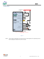
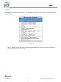
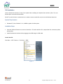
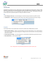
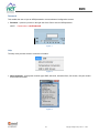
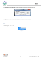
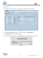
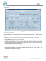
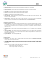
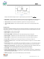
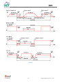
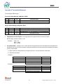
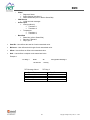
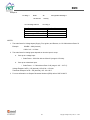
1
EMC EMC Single e-Fan Bank Controller User Manual www.hctcontrols.com 021-00366 Rev A 1 Copyright © High Country Tek, Inc. – 2015 EMC Revision Record Rev Rev A 021-00366 Rev A Description Initial release Date Released Last Updated by 10-Aug-15 BC 2 Copyright © High Country Tek, Inc. – 2015 EMC Contents Revision Record ..............................................................................................................................................2 HCT Introduction ............................................................................................................................................5 Warranty Information ....................................................................................................................................5 Product Use Limitations .................................................................................................................................5 Cautions ......................................................................................................................................................6 Product Application Guidelines ..................................................................................................................6 Controller Specification ..................................................................................................................................7 Controller Dimensions / Mounting Information.........................................................................................8 Wiring Diagram ...........................................................................................................................................9 PINOUT......................................................................................................................................................10 LEDs / Diagnostic Codes ............................................................................................................................11 Accessories ...................................................................................................................................................12 EMC Product Overview ................................................................................................................................13 GUI Installation.............................................................................................................................................14 System Requirements ...............................................................................................................................14 Installation Steps.......................................................................................................................................14 GUI Overview ...............................................................................................................................................15 File .............................................................................................................................................................15 Controller ..................................................................................................................................................15 Password ...................................................................................................................................................16 Help ...........................................................................................................................................................16 Exit ............................................................................................................................................................17 Dashboard .................................................................................................................................................18 Input Setup ...............................................................................................................................................21 Message Select .........................................................................................................................................24 Message Data............................................................................................................................................26 Bank Control .............................................................................................................................................28 Transmit Messages ...................................................................................................................................34 Appendix A Transmitted Messages ..............................................................................................................35 Preconfigured Messages...........................................................................................................................35 Configurable Messages .............................................................................................................................37 Appendix B Troubleshooting Communication Port Adapters .....................................................................42 Overview ...................................................................................................................................................42 Appendix C PID Tuning for Setpoint Control ................................................................................................44 Overview ...................................................................................................................................................44 Tuning Procedure......................................................................................................................................44 Example PID Tuning Results ......................................................................................................................45 021-00366 Rev A 3 Copyright © High Country Tek, Inc. – 2015 EMC This page is intentionally left blank. 021-00366 Rev A 4 Copyright © High Country Tek, Inc. – 2015 EMC HCT Introduction Welcome to High Country Tek Inc. HCT is North America’s foremost independent designer and producer of modular, ruggedized digital and analog electronic controllers for the fluid power industry. From our factory in California, we manufacture ‘specialty’ controllers for specific functions and the user programmable ‘DVC family’ to enable large area networked system solutions. The modules are used in mobile, industrial and marine applications. They are also applied successfully in other industry segments. HCT products are encapsulated in solid flame resistant material for maximum durability, electrical integrity and complete environmental security. HCT is a market leader in many application arenas, including hydraulic generator, e-Fan and hydraulic fan system controls. These controllers facilitate significant fuel, emission and operational savings. HCT’s market neutrality offers integration with any hydraulic OEM valves, pumps, sub-systems or systems. For more information, please visit us at: www.hctcontrols.com. Warranty Information High Country Tek guarantees this product to be free of defects in materials and workmanship for one year from the date shipped from the factory. Within this time frame, High Country Tek will provide evaluation of warranted items free of charge. Warranty repair or replacement will be at the factory’s discretion. Please have the units full Model / Part Number and Serial Number available when contacting the factory. Do not return products to the factory without a RMA (Return Material Authorization) number. Product Use Limitations HCT products may not be suited for any of the following applications: Any product which comes under the Federal Highway Safety Act, namely steering or braking systems for passenger-carrying vehicles or on-highway trucks. Aircraft or space vehicles. Ordinance or military equipment. Life support equipment. Any end product which, when sold, comes under U.S. Nuclear Regulatory Commission rules and regulations. HCT does not have any performance assurance programs for testing their products for the above applications. HCT's products are not designed for these applications and HCT does not warrant, recommend, or specifically approve its products for these applications. The user shall be solely responsible for any loss or damages occasioned by breach of the provisions of this paragraph and shall carry product liability and liability insurance to insure against such loss or damages. 021-00366 Rev A 5 Copyright © High Country Tek, Inc. – 2015 EMC Cautions Changing setup values or operating modes while a machine is running may cause unintended machine movement. It could lead to possible injury or death. Any moving parts should be disabled prior to changing setup values or operating modes. In every case, exercise caution and work should be completed only by qualified personnel. Product Application Guidelines ALWAYS do the following FULLY read this manual and accompanying data sheets BEFORE starting. Isolate this unit from all other equipment BEFORE any form of welding. Isolate the controller from ANY form of battery charging or battery boosting. Be aware of the electrical & mechanical connections, and the expected reactions of the equipment. Operate the units within the temperature range. Use the correct tools to do the job (i.e. P.C., software) etc. Separate High Voltage AC cables from Low Voltage DC signal and supply cables. Make sure power supply is CORRECT, ELECTRICALLY CLEAN, STABLE, and rated for the full load. Make sure the controller output voltage & current is compatible with the equipment. All unused wires / terminals should be terminated safely. Ensure ALL connectors have no unintended SHORT or OPEN circuits. Ensure ALL connectors are wired correctly, secure, locked in place and fully connected. Disconnect or connect wires to or from this unit only when the power supply is disconnected. Use adequate screening in areas of intense Radio Frequency fields. Ensure ALL work areas are clear of personnel before operating the controller. Follow and abide by local and country health & safety standards. 021-00366 Rev A 6 Copyright © High Country Tek, Inc. – 2015 EMC Controller Specification Housing Type HCT encapsulated block, flameproof Power Supply Voltage 9 to 32VDC Current Consumption Load current + 200mA Quiescent (Max) Command Inputs Up to 6 programmable SAE J1939 CAN values Up to 3x option selection switches (ON/Off) Up to 6x inputs for fan diagnostics (ON/Off) Up to 2x sensor inputs (Thermistor or 0-5V) Outputs 1x 0-100% PWM output (sourcing or sinking, Max 500mA, short circuit protection) 1x 500mA on/off output for reverse or alarm indicators (short circuit protection) PWM Freq. Software adjustable - 33 to 1000Hz Module Connector 12-way Deutsch, DTF15-12PB Communication Mini USB Housing Material Black, Polycarbonate Encapsulation Flameproof epoxy resin, black Mounting 3x No. 8 (5mm) SAEGrade 2 screws Temperature Range -40 to +85ºC (Operational) -60 to +150ºC (Storage) NEMA/IP Rating NEMA 6P/IP67 CAN Data Rate 250Kbps, 500Kbps and 1Mbps Certifications CE, E-mark *Check availability 021-00366 Rev A 7 Copyright © High Country Tek, Inc. – 2015 EMC Controller Dimensions / Mounting Information Controller weight is approximately 150g. Mount controller in an easily accessible location. Mount controller to a flat surface. If mounting to a hydraulic product, allow at least a 2mm air gap underneath the unit. Use BOTH mounting holes with correct hardware. DO NOT mount controller with connector facing UP if possible. Recommended, No.8 SAE Grade 2 screws, Dry Torque – 19 in-lbs, Lubricated – 15 in-lbs. 75 Unit: mm 73 50.8 29 1 2 3 4 5 Ø4.7 6 3 x #8 Screw 12 8 11 10 9 8 7 13.5 16.3 58.4 45 Figure 1 021-00366 Rev A 8 Copyright © High Country Tek, Inc. – 2015 EMC Wiring Diagram +V Power Input 9 – 36VDC FUSE PWR 5 DG3 / Rev IP 9 DG2 / Ignition IP 7 DG5 / Sensor IP1 1 Sensor 1 DG6 / Sensor IP2 2 Sensor 2 EMC CAN_H 3 J1939 I/O CAN_L 4 FUSE Single e-Fan Bank Controller FUSE PWM % PWM Output 12 DG1 6 DG4 / Fire IP 11 Rev / Alarm OP 10 500mA On/Off (Sourcing) GND 8 -V (GND) Sample Configuration Shown Note: Some pins have multiple functions configurable with the setup software. Figure 2 NOTE: 021-00366 Rev A The fan output is configurable to work with active low or active high fans. The output duty-cycle can also be configured to reference the on-time or off-time. 9 Copyright © High Country Tek, Inc. – 2015 EMC PINOUT The module has a 12-Pin Deutsch connector. The mini USB port at the top of the controller can be used for serial communication. Figure 3 NOTE: Sensor Inputs 1 and 2 (pins 1 and 2) and digital inputs (pins 7, 9, and 11) can also be configured as Fan Diagnostic inputs within the GUI. 021-00366 Rev A 10 Copyright © High Country Tek, Inc. – 2015 EMC LEDs / Diagnostic Codes Module LED Indicators Reverse/ERROR LED steady GREEN ------------------------------------- Normal operation Reverse/ERROR LED blinks on/off 1 second GREEN ------------------ Low supply voltage Reverse/ERROR LED blinks 1 second RED/GREEN sequence ------ Reverse cycle is active Reverse/ERROR LED steady RED ----------------------------------------- Fire input is active Status LED steady GREEN --------------------------------------------------- Normal operation Status LED blinks on/off 0.1 second GREEN ------------------------------ CAN send/receive event Status LED blinks on/off 0.5 second GREEN ------------------------------ GUI message receive event Status LED blinks on/off 1.5 seconds RED -------------------------------- CAN data message timeout Status LED steady RED ------------------------------------------------------- RPM message timeout (if enabled) When multiple errors occur, the LED sequences through the error codes. Alarm Output Alarm output is OFF ------------------------------------------------------------- No errors Alarm output is ON ------------------------------------------------------------- CAN message timeout Alarm output blinks 0.5 second on/off sequence ------------------------- Diagnostic error Alarm output blinks 1.0 second on/off sequence ------------------------- Reverse cycle is active 021-00366 Rev A 11 Copyright © High Country Tek, Inc. – 2015 EMC Accessories 999-10156 999-10155 108-00134 30-pin Harness (3M length) 12-pin Mating Connector Kit USB Mini B (2M length) 206-00083 (3/8”-18NPT) 206-00083M (M12x1.5) 999-10213 (Mating connector) 206-00084 (3/8”-18NPT) For both liquid and dry thermistors Dry Thermistor -40°C to +150°C. Liquid thermistor -40°C to +150°C. PC-EMC PC set-up software System diagnostics Data logging feature 021-00366 Rev A 12 Copyright © High Country Tek, Inc. – 2015 EMC EMC Product Overview The EMC is a compact but powerful single fan bank controller for use with +12Vdc or +24Vdc variable speed brushless fans. The controller provides a low current varying PWM signal to the fan/s based on command inputs. Setup and system monitoring are easily accomplished through the graphical user interface (GUI). This controller is complete with many selectable input and output configurations along with On-Demand and Set-Point command modes. The health of the fan system can easily be determined by the diagnostic LED’s, the diagnostic J1939 CAN Bus messages from the controller, and by monitoring the system using the software interface. The EMC’s unique PID Set Point feature automatically adjusts the fan speed based upon the user set temperature while prioritizing the multiple thermistor inputs and J1939 messages. For greater performance requirements the OEM can adjust the cooling response by adjusting the PID closed loop settings. The EMC is also unique such that it can be configured through the Graphical User Interface (GUI) to control any combination of Active High and Active Low e-Fans making this a single solution for multiple fan types. The simple and easy-to-use GUI enables the user to perform simple or complex actions based upon the configurable inputs. The GUI is password protected for OEM manufacturers in order to prevent tampering of the pre-tested and qualified OEM configurations. The GUI is designed to have a standard diagnostic dashboard for service technicians that enable access to non-critical functions while obtaining necessary functional information and recording data for troubleshooting or performance monitoring. The EMC is a single economical hardware solution that provides a great deal of functionality making this an affordable solution for the simplest requirements to the most stringent and complex demands. 021-00366 Rev A 13 Copyright © High Country Tek, Inc. – 2015 EMC GUI Installation Use the default file locations for easy future update when installing the Graphical User Interface (GUI). The user has the option to choose the file location. Do NOT run the GUI from a network drive as it needs to access certain files only in the local Windows directories. System Requirements Windows XP, Vista, Windows 7 or 8, 100MB or greater free disk space. Installation Steps Insert the USB and follow the on screen instructions. This will install the GUI, sample data files, thermistor profiles, and help files. Install all software and drivers before plugging in the USB dongle or USB cable. Launch the GUI Click Start HCT Products Fan Drives EMC Figure 4 021-00366 Rev A 14 Copyright © High Country Tek, Inc. – 2015 EMC GUI Overview The EMC GUI is designed to have a default start-up screen with password protected features. When the OEM password is entered, the rest of the tabs will become visible and enable the user to configure the controller. This GUI is configured so that the user can methodically setup each tab from left to right. This manual will cover each tab and help provide a systematic approach to setting up the EMC fan controller. File Save settings to a file (.txt) – saves the settings to a data file that may be loaded into any EMC controller. Load data file – loads the data file from the PC, writes to the controller and permanently saves the settings. Figure 5 Controller The controller button is only accessible when connected to an EMC and the OEM password is entered, Read Controller Settings – loads the controller settings from the Non-Volatile Memory. This is useful when the user wants revert back to the original settings prior to changes made to the GUI that have not been permanently saved to the controller. Permanently Save settings – saves the settings to the controllers Non-Volatile Memory (permanent memory). Reset (Bootloader) – used to update the BIOS. Figure 6 Note: Settings that are not permanently saved will be lost after a power cycle. 021-00366 Rev A 15 Copyright © High Country Tek, Inc. – 2015 EMC Password This enables the user to input an OEM password to access advanced configuration screens. Password – opens a input box on the right side of the GUI to enter an OEM password. NOTE: Passwords are ‘cAsE SeNsitivE’ Figure 7 Help The help menu provides access to controller information. Figure 8 About Controller - displays the controller type, BIOS, Serial No, Activation Date, GUI version, GUI part number and contact information. Figure 9 021-00366 Rev A 16 Copyright © High Country Tek, Inc. – 2015 EMC Temperature Conversion Tool - converts temperature from Celsius to Fahrenheit or vice versa. Figure 10 USB drivers – opens the folder where USB driver installation instruction is located. Exit Exit Program – exits the GUI. Figure 11 021-00366 Rev A 17 Copyright © High Country Tek, Inc. – 2015 EMC Dashboard The Dashboard monitors the fan system in real time. This is the only screen available without and OEM level password. The dashboard provides input and output monitoring, data-logging, engine rpm, communication status, and provides manual fan control when selected. Figure 12 Data Logging Sample Time Seconds – adjust the sample time when taking data. This will also slow down the speed that the graphs moves along X axis. Default sample time is 1 second. If “0” is entered, the controller will log as fast as possible based on the communication bandwidth (review data log file for exact time). Back ground Color – click to change the background color. Log Data – logs the operational data in .csv format and will continue to log data until the data limit is reached. For a csv. file, this is typically 15,000 cells. If the sample time is 1 second, this is roughly 250 minutes. Communication Status Connection Status – This window displays the communication between the GUI and the EMC control module. Work Off Line – a Work Off Line button becomes available if the GUI cannot establish a connection with an EMC controller. This will allow the user to work with GUI offline without the module connected. The user can load existing data files, modify them or create new data files, and save them to the PC without an OEM password. 021-00366 Rev A 18 Copyright © High Country Tek, Inc. – 2015 EMC Status Messages State Indicators – displays the state of the inputs, Supply Voltage, RPM Status, Msg. Status, Msg. Data Status, and Analog Status. o Switch Input Indicators – displays the active state of the input, Ignition, Fire, and Reverse. Unless these inputs are selected on the Input Setup tab, they will be grayed out. Blue fill – the switch is active. Empty – the switch is inactive. Grayed out – the switch is not used. o Supply Voltage – indicates the controller voltage is within operational range, above 9 volts. Green – the controller supply voltage is above 9 volts. Yellow – the controller supply voltage is below 9 volts. o RPM Status – indicates the operational health of the engine RPM. Green – the engine RPM is operating above the minimum RPM set speed. Yellow – the engine RPM is below the minimum RPM set speed. o Msg. Status – Indicates if the J1939 CAN message inputs are being received. Green – the CAN Bus messages are being received. Red – the CAN Bus messages have an error such as loss of communication. o Msg. Data Status – Indicates if the J1939 CAN stimulus inputs are within user defined operational limits. Green – the stimulus is within defined limits. Red – the stimulus is off, timed out, or outside of operational limits Stimulus Inputs Stimulus 1-4 – displays the stimulus configured within Bank Control. Any input not activated will be grayed out. Value – displays the real time value of the stimulus input. Demand % - displays the real time PWM% demand for the corresponding input stimulus. Stimulus State Indicator – this is an indicator for transmitted and measured stimulus inputs (only visible when a CAN Bus message is selected for a stimulus). Green – the input is on or active. Red – Message timeout or the value is within the Alarm High or Alarm Low values. Diagnostic Input Status Stimulus 1-4 – diagnostic inputs will be green if there is no error while the fan is operations. The indicators turn grey when the diagnostic is in a failed state. 021-00366 Rev A 19 Copyright © High Country Tek, Inc. – 2015 EMC Fan Status Fan Status - There are six operational states. Normal – The fan bank is operating normally. Diag. Error – At least one fan in this bank is reporting an error. Manual – Manual mode is active. Reset – At least one Locked Rotor error was detected. The module is resetting all the fans in this bank. Dwell – The fans in this bank are transitioning into reverse direction. Reverse – The fans in this bank are in Reverse. Fan RPM – this bar graph displays the calculated rpm of the fan/s. Fan Drive PWM% - this bar graph displays the real time total duty cycle demand for the fan bank. Engine RPM This is displayed as a gauge when receiving the Engine RPM from engine control unit via CAN Bus(SAE J1939). Manual Mode This mode allows the user to verify the E-fans are working properly and determine the maximum, minimum and reverse PWM duty cycles. Enable / Disable Switch – turns On/Off manual control. % Fan Speed – displays the real time percent fan speed of the fan bank. Manual % Fan Speed – displays the command input for this fan bank. To change the input, the user can drag the bar, type the value, or increase/decrease arrow. Caution These settings will immediately affect the output. All limits and controls are bypassed. The controller goes back to normal operation when disabling the manual mode. Cycling power on the unit will exit the manual model. Disconnecting the communication cable will exit manual mode. 021-00366 Rev A 20 Copyright © High Country Tek, Inc. – 2015 EMC Input Setup This screen is used to setup all of the analog inputs, digital inputs, diagnostic inputs, value interlock, and RPM interlock. Figure 13 Write Settings – saves any changes made to the controller’s volatile memory and executes. It’s very important to click on this button after changes have been made or the new changes will not take affect. It does not save settings permanently, a Power Cycle will restore permanently saved settings. Select Input Conditions Inputs – Use the drop down box to select the available input configuration for that particular input. Choices include Thermistor, Voltage, Diagnostic, or Digital input type (Reverse, Ignition, or Fire). Note: If an input is not being used, simply select “Diagnostic” for that input. This input will be ignored as long as the corresponding diagnostic input is not activated under “Active Diagnostic Inputs for Fan Status”. Pull-Up – Determines the polarity state of the input. Pull up is used when the input drives the voltage low when active. Pull low is used when the input drives the voltage high when active. Active – displays the state of the input, active High or active Low. Thermistor Profile Select – select thermistor input profiles. Each thermistor input has the option of selecting stored profiles located in the EMC root directory. Current profiles available are listed below: o o 021-00366 Rev A Delphi 15236386.dat – Standard thermistor profile. Delphi 15236386DG.dat – thermistor profile with open and short detection. 21 Copyright © High Country Tek, Inc. – 2015 EMC Open Value & Short Value – these value input boxes become available when the thermistor profile Delphi 15236386DG is selected. The values entered represent the default speed the fans will run at if these errors are detected. Active = no errors – defines the error state of the diagnostic inputs when active. Frequency Input Active – select this input when using an e-Fan that outputs a diagnostic frequency. Refer to the fan specification to determine the type of diagnostic output. Reset Locked Fan Fault – when selected, the controller will re-set the Locked Fan Fault and attempt normal operation again after the specified Timeout time. Otherwise the fan will remain in an inoperable fault state. Activate Diagnostic Inputs for Fan Status – Select the available fan diagnostic inputs to activate. Manual Reverse Conditions This displays conditions in order to activate the manual reverse feature. The manual reverse function is allowed only when the fire input is off and the ignition is on unless the inputs are disabled. Engine RPM is Off/low – if checked, Manual Reverse is allowed when the Engine RPM is lower than the Minimum Engine RPM. Engine RPM is ignored – when checked, Manual Reverse is allowed regardless of engine RPM. Value Interlock Setup This feature allows the ability to use any active stimulus as an interlock. Simply select the active stimulus and the type in the interlock value you wish to use. When the Greater than Value check box is selected, the stimulus selected will operate normally as long as the current stimulus value is greater than the interlock value. If the value goes below the interlock value, the stimulus will be disabled. If the stimulus is a J1939 message, the fan output will default to its Error Value. If Less Than Value is selected. Then the stimulus selected will operate normally as long as the current stimulus is less than the interlock value. If the values rises above the interlock value, the stimulus will be disabled. If the stimulus is a J1939 message, the fan output will default to its Error Value. Interlock Selection Minimum RPM – check to enable the input. When enabled, the fan bank will not run until the Engine RPM meets or exceeds the Minimum Engine RPM set point. Ignition Input – This input is enabled from the Select Input Conditions section. Fire Input – This input is enabled from the Select Input Conditions section. The fire input will override all controlling inputs. When the Fire Input switch is activated, this fan bank stops. Manual mode overrides the fire input. Display Interlock Truth Table – opens a window that displays a truth table of the interlock logic. 021-00366 Rev A 22 Copyright © High Country Tek, Inc. – 2015 EMC Figure 14 021-00366 Rev A 23 Copyright © High Country Tek, Inc. – 2015 EMC Message Select The user may define up to 6 CAN messages as the controlling inputs. The EMC supports the SAE J1939 protocol. NOTE: The first message is always EEC1, Engine RPM (hard coded). Figure 15 Preload Message – opens the control message file and displays the Message Window. Figure 16 o Select PGN or Select Message Name, the GUI will match PGN and Message Name. o Accept or Cancel the message. o Check to enable the message. o Select SAE J1939 as the CAN Msg. Format. 021-00366 Rev A 24 Copyright © High Country Tek, Inc. – 2015 EMC Mask SA – if checked, the source address is ignored. The module can receive messages from any source address for the specified PGN number. Hex/Decimal Switch – switches PGN numbers between Hexadecimal or Decimal format. Message Name – for custom messages, manually enter a description of the received message. Time-Out – defines the amount of time a messaged can be timed-out before displaying a fault condition. Msg. State – indicates if the command message is being received on the J1939 Bus. Green – the message is Active. Red – the message is Timed Out. 021-00366 Rev A 25 Copyright © High Country Tek, Inc. – 2015 EMC Message Data This tab defines the message information in continuation from the Message Select tab configuration. Figure 17 Select specific Control Message from the pull-down menu defined in “Control Messages” Tab. Select SPN Selection text file. A new window will open. Select the stimulus from the pull-down menu Stimulus (SPN), the respective values appear automatically. Figure 18 021-00366 Rev A 26 Copyright © High Country Tek, Inc. – 2015 EMC The stimulus has to match the control message. E.g., SPN177 Transmission Oil Temperature matches J1939 TF. If the Stimulus does not match the Control Message, this window will appear: Figure 19 Start Bit – The bit number where the data begins. Bit numbering starts at 0. Read Bits – The number of bits in the data package. Offset – The offset is applied after the Gain Calculation. Gain – The Scale Factor for the Gain Calculation. Error Value – the value used for the stimulus when the message times out. Units – the unit of the stimulus value. 021-00366 Rev A 27 Copyright © High Country Tek, Inc. – 2015 EMC Bank Control Figure 20 Setup Fan Bank Parameters The user may define up to four stimulus inputs. The fan bank utilizes the temperature or voltage settings to calculate the PWM% demand for the fan bank. If a bank is not used, simply select “stimulus” for from the drop down menu. Stimulus 1-4 – selects stimuli for this bank. All previously configured stimuli are in the pull down menu. . Stimulus Grouping – the stimulus inputs can be grouped. Group No. – When a stimulus reaches a value that is out of range, as defined by the Alarm High and Alarm Low settings and is not grouped (left as Group No.), then the fan bank will default to the % of Fan Speed condition. For example, if two stimulus inputs were selected and both were set to “Group No.”, then if either input faulted, the fan bank would operate under the fault condition. Group 1 or Group 2 – If stimulus inputs are grouped together (either Group 1 or Group 2), then if one of the stimuls sees a fault condition, it will check the other stimuli in the same group and operate to the stimulus that is in an operations state. For example, if stimulus 1 and 2 are both grouped as Group 1 and stimulus 1 reaches an alarm set point, but Stimulus 2 is still within the operation limits, then fan bank ignores Stimulus 1 and continues to operate with Stimulus 2 as priority. 021-00366 Rev A 28 Copyright © High Country Tek, Inc. – 2015 EMC Maximum Set-Point – the stimulus value that commands the fan bank to run at full speed. Minimum Set-Point – the stimulus value that commands the fan bank to run at minimum speed. Alarm High – the stimulus value that activates the High Alarm condition. Alarm Low – the stimulus value that activates the Low Alarm condition. Demand % – displays the current percentage of demand. Alarm Indicator – displays green as long as the input does not exceed Alarm High or Alarm Low limits. Will display red if limits are exceeded. Message State – displays green when normal, red when timed out. A timeout occurs when the message has not been received for a period greater than the Time Out setting in the Control Messages tab. Conditions for Fan Speed Limit Message Timeout – when checked, the fan speed defaults to the % of Fan Speed specified by the user if there is a message timeout. If stimulus is grouped and there is a message timeout indicated on the Message State, the fan bank does not default to the % of Fan Speed as long as there is an additional valid stimulus within the same Group 1 or 2. Diagnostic Error – when checked, the fan bank speed defaults to the % of Fan Speed if there is diagnostic error. Low Engine RPM – when checked, the fan bank speed defaults to the % of Fan Speed if the engine RPM is lower than the RPM defined, but it must also be higher than the Minimum Engine RPM in the Input Setup tab if Engine RPM interlock is used. Engine RPM Value – enter low engine RPM value. Fan Bank Features PID Control – when checked, the user enables the PID control feature. Refer to the Set-Point Control (PID) section of this manual for more information. Invert Duty Cycle – enables the negative logic duty cycle when the checkbox is selected. The EMC default (unchecked) is positive logic duty cycle. Reference the e-fan spec sheet in order to determine which definition the fan uses. Example: This is an example of “positive logic duty cycle”, see Figure 21. - 021-00366 Rev A Continuous low voltage is 0% duty cycle Continuous high voltage is 100% duty cycle 29 Copyright © High Country Tek, Inc. – 2015 EMC Figure 21 Using the same waveform diagram, Figure 21, negative logic duty cycle would be: 𝐷 = 𝑇𝐿 𝑇∗100[%] Auto Reverse – When checked, the automatic fan reverse cycle occurring after a time interval period is enabled. When unchecked, the fans will reverse only if the reverse input is toggled with the reverse switch. Reverse Ind. Out – when checked, the Alarm/Rev. output will turn on during the reverse cycle. Alarm Ind. (Msg. Timeout) – when checked, the Alarm/Rev. output will turn on (sourcing) during an alarm event. Fan Bank Profile This defines the operational properties of the e-fan used for the specific bank. It is important to refer to the e-Fan specifications for this section. The displayed values in the GUI will not be accurate if theses settings are not correct. Maximum RPM – the rated maximum fan RPM. Minimum RPM – the rated minimum fan RPM. Zero Fan Speed PWM – the PWM duty cycle % that causes the fan(s) to stop, see Figure 22. Maximum PWM – the PWM duty cycle % that causes the fan(s) to run at maximum RPM, see Figure 22. Minimum PWM – the PWM duty cycle % that causes the fan(s) to run at minimum RPM, see Figure 22. Reverse PWM – the PWM duty cycle % that causes the fan(s) to run in Reverse, see Figure 22. Auto Reverse Interval (minutes) – see the EMC reverse cycle definition, see Figure 23. It is the time between reverse cycles. Reverse Period (seconds) – see the EMC reverse cycle definition, see Figure 23. It is the total time to ramp up in reverse direction, run in reverse, then ramp down time. Ramp up and down time are equal to the dwell time. Minimum Run Time Seconds – the minimum run time. It prevents the fans from repeatedly starting and stopping when there is low demand and helps reduce thermal cycling in the equipment. Default PWM – this is the default PWM duty cycle % that the fan will run at no demand. Direction Change Dwell (Seconds) – see the EMC reverse cycle definition, see Figure 23. The dwell time is the time it takes to ramp down and go into reverse mode. It also is the time it takes to ramp down from reverse mode before driving the fans normally. PWM Frequency (Hz) – is the user defined PWM frequency for the E-fans banks. 021-00366 Rev A 30 Copyright © High Country Tek, Inc. – 2015 EMC Minimum PWM Maximum PWM Zero Fan Speed PWM Reverse PWM Figure 22 021-00366 Rev A 31 Copyright © High Country Tek, Inc. – 2015 EMC Figure 23 021-00366 Rev A 32 Copyright © High Country Tek, Inc. – 2015 EMC Set-Point Control (PID) This is a precise closed loop control feature that automatically compensates to a changing Stimulus input. The PID settings can be adjusted to increase or reduce the response characteristics due to changing Stimulus input. This feature only closes loop on a single stimulus input. For an overview of PID control and simplified tuning procedure, refer to Appendix C PID Tuning for Set-Point Control. Figure 24 PID Control – enables the Set-Point Control feature. When this is selected Stimuli 2 - 4 become nonfunctional and the PID terms become available. For more information on PID tuning and expected system response, see Appendix C PID Tuning for Set-Point Control. o P – this is the proportional gain for the PID control loop and ranges from 0 to 1000. o I – this is the integral term of the PID control loop and ranges from 0 to 1000. o D – this is the derivative term of the PID control loop and ranges from 0 to 1000. Note: During in-house testing, a typical PID setting that showed favorable results was: P=150, I=5, D=0. 021-00366 Rev A 33 Copyright © High Country Tek, Inc. – 2015 EMC Transmit Messages The EMC can transmit module status messages via SAE J1939. The user can choose between preconfigured messages or configure their own messages. Refer to Appendix A for more details. Figure 25 Message Data Rate - is the CAN data rate. The EMC supports 250K, 500K or 1000Kbps. It must match the J1939 bus to ensure the communication. 021-00366 Rev A 34 Copyright © High Country Tek, Inc. – 2015 EMC Appendix A Transmitted Messages Preconfigured Messages Fan Control State Message, PGN 65213, FEBD SPN Start bit # bits Parameter Name 975 1 8 Estimated Percent Fan Speed (0-100%) 977 9 4 Fan Control State Bank 1 Status Message, PGN 45312, B100 SPN Start bit # bits Parameter Name 975 1 9 17 8 8 16 Bank Estimated % Fan Speed (0-100%) DG State Input 1 – 6, 0 = Fan failure, 1 = Fan is Operational Estimated Fan RPM 1639 Estimated Percent Fan Speed – an average percent fan speed (0-100%) of active fan bank. NOTE: Range is 0-250, each bit = 0.4% Example: 0x00 = 0% 0xFA = 100% 0xA7 = 66.8% Fan Control State – assigns a 0 or E. When stimulus are grouped, the fan control state will only display an E if all stimulus are in an error state, otherwise ungrouped stimulus will override the grouped messages and display an E if in a failed state. 0 = Error if stimulus is within alarm low or high levels and or if any DG bit shows a fan failure. E = Normal fan operation Example 1: Stimulus Stimulus 1 Stimulus 2 Stimulus 3 Group Group 1 Group 1 Group 1 Transmitted Fan Control State Control State E E 0 0 Group None Group 1 Group 1 Transmitted Fan Control State Control State E 0 0 E Example 2: Stimulus Stimulus 1 Stimulus 2 Stimulus 3 . 021-00366 Rev A 35 Copyright © High Country Tek, Inc. – 2015 EMC Bank Estimated % Fan Speed – calculated percent fan speed (0-100%) of selected bank. NOTE: Range is 0-250, each bit = 0.4% Example: 0x00 = 0% 0xFA = 100% 0xA7 = 66.8% DG State Input 1 - 6 – assigns a 0 or 1 for up to 6 fan diagnostic inputs for selected fan bank. 0 = Fan failure 1 = Fan is operating or not selected for this bank NOTE: This is true for all cases regardless if the fan is configured with an inverted waveform. Estimated Fan RPM – calculates the fan speed based upon user configurations in the Bank Control tab of the GUI (multiply by 0.125 RPM/bit for RPM value). Example: Byte 3 Byte 4 Fan RPM Low Side Byte Fan RPM High Side Byte Byte 3 = 4A Byte 4 = 39 0 x 394A = 14666 (decimal) 14666 x 0.125 = 1833.25 RPM 021-00366 Rev A 36 Copyright © High Country Tek, Inc. – 2015 EMC Configurable Messages Figure 26 PGN # – User defined. Factory setting is B500. SA – User defined. Factory setting is 4E. Interval – Message transmit frequency (units are in milliseconds). Priority – Assigns the message priority. TXT Msg. Values (1-8) – Select up to 8 values to transmit. TXT Msg. – Assigns the selected TXT Msg. Value to TXT Msg. 3 or 4. Data Type – Each value can be transmitted as a float or integer. o Float – Values sent as float messages are 32 bits long. o Integer – The bit length of values sent as integers are defined by the user. Data Source – There are four primary data sources. Each data source contains its’ own set of data values or stimulus messages, outlined below. 021-00366 Rev A 37 Copyright © High Country Tek, Inc. – 2015 EMC o o o o Global Diagnostic Status Supply Voltage (see Note 1) Device Status bits (refer to Device Status Bits) CAN Receive J1939 received messages Sensor Input Volts (see Note 2) Thermistor 1 Thermistor 2 Temperature Thermistor 1 Thermistor 2 Bank Data Status bits (refer to Status Bits) Stimulus % Demand Duty Cycle % Start Bit – User defines the start bit of each transmitted value. Bit Count – User defines the bit length of each transmitted value. Offset – User defines an offset to the transmitted value. Gain – User defines a multiplier to the transmitted value. Example 1: TXT Msg. 3 B500 4E 750 Interval 7 Priority TXT Message Value 1 TXT Msg. 3 Data Type – Float Data Source – Global Global Value – Supply Voltage Supply Voltage 021-00366 Rev A Configurable Message 1 38 0 – Start Bit 32 – Bit Count 0 – Offset 1 – Gain Volts – Units Copyright © High Country Tek, Inc. – 2015 EMC Example 2: TXT Msg. 3 B500 4E 750 Interval 7 Priority TXT Message Value 2 Configurable Message 1 TXT Msg. 3 Data Type – Integer Data Source – Global Global Value – Supply Voltage Supply Voltage 32 – Start Bit 16 – Bit Count 0 – Offset 0.01 – Gain Volts – Units NOTES: 1. The scale factor for Voltage Inputs (Supply, Fire, Ignition, and Reverse, is 0.01 V/bit with an offset of 0. Example: 0x04B0 = 1200 (decimal) 1200 x 0.01 = 12 Volts 2. The scale factor for Analog Inputs depends on how the input is set up. a. If set up as a voltage input: i. Scale Factor – 0.02 V/bit with an offset of 0 (range is 0-5 Volts). b. If set up as a thermistor input: i. Scale Factor – 1° C/bit with an offset of -40 (range is -40° – 215° C). Voltage Example: 0x7D = 125 (decimal), 125 x 0.02 = 2.5 Volts Thermistor Example: 0x7D = 125 (decimal), 125 - 40 = 85°C 3. For more information on Suspect Parameter Numbers (SPN) refer to SAE J1939-71 021-00366 Rev A 39 Copyright © High Country Tek, Inc. – 2015 EMC Device Status Bits The Device Status Bits are available when Global is selected as the Data Source within the transmit message tab. When selected, the user must assign 16 as the bit count. Only 10 of the 16 bits are used. 021-00366 Rev A Start bit # bits Parameter Name 1 2 3 4 5 6 1 1 1 1 1 1 1 = Supply voltage lower than 9V 1 = J1939 RPM message timeout 1 = J1939 data message timeout 1 = Fire input is on 1 = Ignition input is on 1 = Reverse input is on 7 8 9 10 11 12 1 1 1 1 1 1 1 = One or more diagnostic error active 1 = One or more Analog value out of range 1 = One or more CAN data values out of range Unused Unused Unused 13 14 15 16 1 1 1 1 1 = Low Engine RPM Unused Unused Unused 40 Copyright © High Country Tek, Inc. – 2015 EMC Status Bits The Status Bits are available when Bank Data is selected as the Data Source within the transmit message tab. When selected, the user must assign 16 as the bit count. Only 9 of the 16 bits are used. 021-00366 Rev A Start bit # bits Parameter Name 1 2 3 4 5 6 1 1 1 1 1 1 1 = Data value out of range 1 = J1939 message timeout 1 = J1939 data message timeout 1 = In reverse cycle 1 = Direction change 1 = One or more diagnostic error active 7 8 9 10 11 12 1 1 1 1 1 1 1 = Diagnostic reset cycle 1 = Manual mode active 1 = All fans have spun Unused Unused Unused 13 14 15 16 1 1 1 1 Unused Unused Unused Unused 41 Copyright © High Country Tek, Inc. – 2015 EMC Appendix B Troubleshooting Communication Port Adapters Overview Windows does not like Com ports with the same name, and some devices might hang onto a com port when not in use. Here is how to clean and remove problem ports. Option 1 Devices that have been installed but are not currently available are "phantom devices". These devices are not usually displayed in the device manager, but can be made to be displayed. This allows device properties to be changed or devices to be uninstalled even though the device is not physically connected to the PC. Control Panel System Properties "Advanced" option and click "Environment Variables" In the System Variables sections, click "New" "DevMgr_Show_NonPresent_Devices" and set the value to 1 OK Close the System Properties panel. Figure 28 Figure 27 Figure 29 021-00366 Rev A 42 Copyright © High Country Tek, Inc. – 2015 EMC Open the Device Manager "View” Show Hidden Devices". Device Manager will show all hidden and phantom devices. Uninstall the phantom devices by right clicking on them, and 'delete'. Reboot the PC. Figure 30 Figure 31 Option 2 Open the Control Panel: Add or Remove Programs Remove old versions of FTDI drivers Windows Driver Package – FTDI CDM Driver Package Reinstall the FTDI Drivers as explained in Software Installation above. The current driver package for your operating system may be obtained directly from the vendor at http://www.ftdichip.com/FTDrivers.htm 021-00366 Rev A 43 Copyright © High Country Tek, Inc. – 2015 EMC Appendix C PID Tuning for Set-Point Control Overview The process of setting the optimal gains for P, I and D to get an ideal response from a closed loop control system is called tuning. Tuning Procedure This is a trial and error method. 1) Set the I and D terms to zero first 2) Increase the proportional term (P) until the output oscillates after a step change to the set point. 3) As the proportional gain is increased, the system response becomes faster (don’t increase P too much otherwise the system could become unstable). 4) Increase the integral term (I) to reduce the steady state error (difference between the set point and the actual feedback value at steady state). The integral term reduces the steady state error, but increases overshoot. Some amount of overshoot is always necessary for a fast system so that it can respond to changes quickly. 5) If needed, increase the derivative term (D) until the system response is acceptably quick to a step change with minimal overshoot. Increasing the derivative term decreases overshoot and yields higher gain with stability. Figure 32 021-00366 Rev A 44 Copyright © High Country Tek, Inc. – 2015 EMC Example PID Tuning Results Use the EMC GUI data logger to plot the response of the system in order to see how the PID terms affect the temperature response. The system should be able to reach and maintain the set-point temperature quickly if the mechanics of the cooling system are designed correctly. During the PID tuning process, it is important to keep in mind that all systems are different and accurately tuning the PID system can take time. Adjust one variable at a time and allow the system to reach steady state in order to compare the system responses. For a good starting point, use P=150, I=5, and D=0 with a Process Time of 1 second. Below are the test results of a dynamic cooling system and demonstrate the approach of tuning the PID set-point control. Test01 Setpoint = 45 deg C P=40, I=5, D=0 120 Temperature (deg C) % Fan Speed (0-100%) 100 80 60 % Fan Speed Thermistor1 40 20 0 0.00 10.00 20.00 30.00 Time (mins) 40.00 50.00 60.00 Figure 33 This image shows about a 40 minute settling time for the temperature to reach the set point. This also demonstrates an unstable system. 021-00366 Rev A 45 Copyright © High Country Tek, Inc. – 2015 EMC Test02 Setpoint = 45 deg C P=100, I=5, D=0 120 Temperature (deg C) % Fan Speed (0-100%) 100 80 60 % Fan Speed Thermistor1 40 20 0 0.00 1.00 2.00 3.00 4.00 Time (mins) 5.00 6.00 7.00 8.00 Figure 34 This figure displays an increase in performance by increasing the P term from 40 to 100. The settling time of the setpoint temperatures reduced to a few minutes. The system responds quickly to an increase in measured temperature around 6 minutes and settles at a higher % fan speed in order to maintain the set-point temperature. 021-00366 Rev A 46 Copyright © High Country Tek, Inc. – 2015 EMC Test03 Setpoint = 45 deg C P=150, I=5, D=0 120 Temperature (deg C) % Fan Speed (0-100%) 100 80 60 % Fan Speed Thermistor1 40 20 0 0.00 2.00 4.00 6.00 8.00 10.00 12.00 14.00 16.00 Time (mins) Figure 35 This figure represents an increase in the system’s ability to maintain the set-point temperature by increasing the P term from 100 to 150. 021-00366 Rev A 47 Copyright © High Country Tek, Inc. – 2015 - - For a full list of authori ed distributors worldwide, please visit: For customer service, pricing, order placement and application support, contact us through E-mail at: A S N Hydraulics C ompany 08 Gold Flat Court Nevada City, CA, 9 9 9 Tel: (1 30 3 3 Fax:(1 30 3