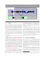
1
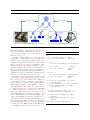
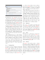
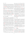
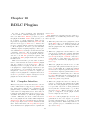
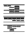
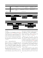
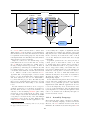
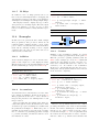
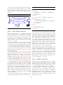
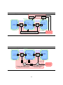
are the parts which are unique to Fleet, and are
added to the normal RDLC2 mapping flow (see Section 31).
In particular the Fleet compiler is actually a
highly parameterized Fleet assembler, because it
takes not only a Fleet assembly language program
but an RDL description of the hardware to run it
on. The parameters listed in Section 13.2.1 determine not only the structure of the processor, but
of course the binary encoding of the instructions
which it must generate.
Aside from the main command plugins there are
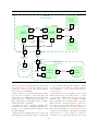
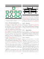
several other specialized Fleet builder RDLC2 plugins. In particular the horns and funnels are generated by a pair of aptly named plugins which are
responsible for creating the binary tree structure.
This could of course easily be replaced by generators for a different switch fabric topology.
Finally the Ships in the Ships unit are connected
to the boxes by a plugin designed for this purpose.
The connector plugin will search all of the RDL unit
instances inside of the Ships unit for RDL ports
which are of the proper type, and unconnected.
This hides all the details of connecting ports properly based on their type, and managing the assignment of port address to Ship ports. Thus a Fleet
program which is compiled directly to a Fleet never
needs to contain numeric aliases, as they can be extracted from the RDL source code.
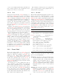
The correspondence between Ship ports and
switch fabric addresses, as well as the result of
the Fleet compiler stage of the toolflow combine
to produce a memory image containing the assembled code. This memory image is then loaded in
to the read-only instruction memory through the
usual RDLC2 memory generation plugins (see Section 10.4.3).
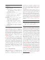
In the end the code produced from this process
is a Verilog description of a complete Fleet with an
initialized instruction ROM. This description can
be tailored, in RDL, for either an FPGA or HDL
simulator implementation.
13.3
13.3.1
Unit: Adder
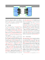
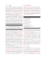
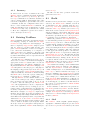
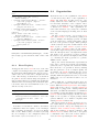
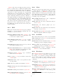
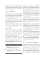
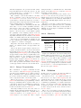
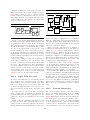
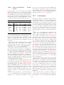
The adder Ship, whose ports are listed in Table 7,
is fairly self explanatory. What is notable are the
firing rules, which state that it will perform one
addition for each pair of inputs and consume them
in the process.
Table 7 Adder Ports
Dir
In
Type
Integer
Name
Adder
In
Integer
Addend
Out
Integer
Sum
13.3.2
Description
One of the two values to be added
One of the two values to be added
The sum of the
two inputs
Unit: Comparator
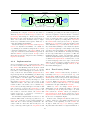
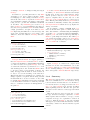
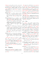
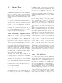
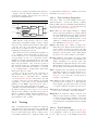
The comparator Ship, whose ports are listed in Table 8, takes two integers and produces a boolean.
The input ports are labeled according to which one
should be larger for the output to be true.
Table 8 Comparator Ports
Dir
In
Type
Integer
Name
Small
In
Integer
Large
Out
Boolean
Result
13.3.3
Description
The smaller of the
two inputs
The larger of the
two inputs
True if the larger
input actually is
Unit: Multiplexor
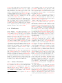
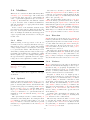
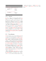
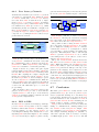
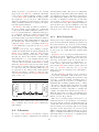
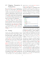
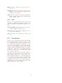
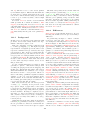
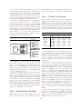
The multiplexor Ship, whose ports are listed in Table 9, takes two variants and a boolean and sends
one of the variants to its output.
Table 9 Multiplexor Ports
Ships
In this section we describe the details of ports and
operation of the various Ships which we have implemented. This is not intended as a complete list of
Ships, as it is not clear what applications they can
or cannot efficiently support. Instead this is merely
a small example of the kinds of Ships we envision,
and those necessary to run the examples shown in
Section 13.4.
117
Dir
In
In
In
Type
Variant
Variant
Boolean
Name
Input0
Input1
Select
Out
Variant
Result
Description
The false input
The true input
A selector between the two
inputs
The selected input