1
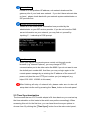
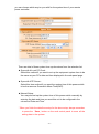
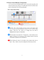
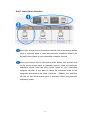
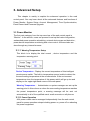
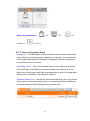
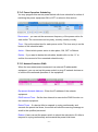
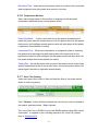
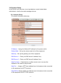
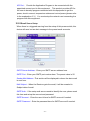
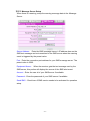
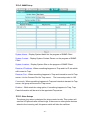
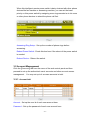
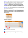
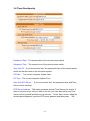
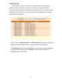
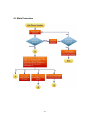
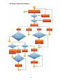
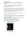
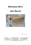
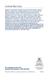
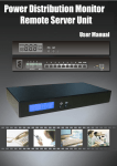
INDEX 1. PRODUCT INTRODUCTION .................................................................................................... 1 1-1 RANGE OF APPLICATION ................................................................................................................. 1 1-2 POWER CONTROL AND CURRENT STATUS MONITORING DIAGRAM ................................................ 2 1-3 PRODUCT FEATURES ....................................................................................................................... 3 1-4 HARDWARE ENVIRONMENTAL EXPLANATION ................................................................................. 4 1-5 POWER ENVIRONMENTAL EXPLANATION ........................................................................................ 5 1-6 HARDWARE INSTALLATION ............................................................................................................. 5 1-7 PRODUCT PACKAGING .................................................................................................................... 6 2. INTERNET WEB OPERATION ...................................................................................................... 7 2-1 ONLINE SETUP ................................................................................................................................ 7 2-2 NETWORK SETUP ............................................................................................................................ 8 2-3 TIME SYNCHRONIZATION................................................................................................................ 9 2-4 POWER CONTROL MONITOR CONFIGURATION .............................................................................. 11 2-4-1 Power Switch Setup............................................................................................................ 11 2-4-2 Power Switch Operation ..................................................................................................... 12 3. ADVANCED SETUP ........................................................................................................................ 13 3-1 POWER MONITOR ......................................................................................................................... 13 3-1-1 Warning Temperature Setup ............................................................................................... 13 3-1-2 Power Operation ................................................................................................................. 13 3-1-3 Power Configuration Setup ................................................................................................ 14 3-1-4 Power Operation Scheduling .............................................................................................. 15 3-1-5 Network Detection PING ................................................................................................... 15 3-1-6 Temperature Monitor .......................................................................................................... 16 3-1-7 Voice File Sending.............................................................................................................. 16 3-2 SYSTEM SETUP ............................................................................................................................. 17 3-2-1 Network Setup ..................................................................................................................... 17 3-2-2 Email Server Setup .............................................................................................................. 18 3-2-3 Message Server Setup ........................................................................................................ 19 3-2-4 SNMP Setup ....................................................................................................................... 20 3-2-5 Other Setups ....................................................................................................................... 20 3-3 ACCOUNT MANAGEMENT ............................................................................................................. 21 3-3-1 Account Add ....................................................................................................................... 21 3-3-2 Delete User Account ............................................................................................................ 22 3-4 TIME SIMULTANEITY .................................................................................................................... 23 -i- 3-5 EVENT LOG .................................................................................................................................. 24 4. PHONETIC OPERATION PROCEDURE .................................................................................... 25 4-1 MAIN PROCEDURE ........................................................................................................................ 26 4-2 POWER CONTROL PROCEDURE ..................................................................................................... 27 - ii - 1. Product Introduction Our IP-P3 professional remote power switch/distribution system integrates versatile functions including power control, electric current monitoring, temperature monitoring, remote web administration, voice control, event alert into one singe unit, which helps system administrator or IT personnel monitor and control the power status of their equipments connected and take preventive measures if needed. By building centralized power control system for power equipments such as UPS, power generator, fan, lighting, signage, network routers/hubs/switches, DSL/Cable modems, ATM's, servers, gateways, web cams, video cameras, firewalls and security / surveillance system, this remote power switch helps reduce greatly on enterprises' IT cost as well as saves MIS personnel’s traveling time. Other benefits from employing this intelligent power distribution system including: Improves administrative efficiencies with multi-outlet power control. Reduces system down time so business operation will not be interrupted. Restores IT assets without dispatching service personnel to remote Data Centers The monitoring and management of the computer equipment room. The remote power monitoring and environment management of data centers, network equipment, machinery equipment and etc. 1-1 Range of Application Monitoring and management of the computer equipment room. Intelligent power management of data center and networking equipments Power scheduling of all machinery equipment for the factory building. Home appliance power control and monitoring. Other power equipment management, scheduling and monitoring. -1- 1-2 Power Control And Current Status Monitoring Diagram -2- 1-3 Product Features Professional IP-addressable power distribution unit with built-in web server with 4 power outlets. A new way to control power supply of the remote equipments via internet web interface or telephone keypad without the presence of personnel. Amazing power distribution unit equipped with an intelligent current-meter (True RMS) to indicate the total power consumption of a power strip. Manual power on/off button to override the existing power status and gain immediate control from local access. Each AC power outlet can be independently switched on/ off, power cycled for immediate reboots or reboot with timed delays, power cycle sequence with assigned priority and power event scheduling. Easy LED displays for power status, total current and control mode indication. Featured with AC (RMS) current meter built in to display the total current load of the switch from the devices connected. Supports temperature monitor function to detect the monitored site's surrounding temp through the integrated temperature sensor. Supports Power Start sequence setting to prevent all of switches from starting simultaneously to cause sudden overloading and effect equipment working. Easy web setup for scheduling power operations precisely performed on specific outlet daily, weekly, monthly and yearly. The Auto-Ping feature will monitor and auto detect any failed network equipment and perform a timed reboot or other power control function (like turning on an indicator or siren). IP filter/mask function helps manage user privileges and prevent unauthorized access to the control menu through the network. Instant email, SMS text messages and trap notification will be generated when power events occurred according to the preset values. Fail-safe RS-232 communication port connection available when network is down or phone disconnected. Protected with circuit breaker to avoid power overload and protect connected devices. Rack mountable design with holes on the side of the metal enclosure for when using optional rack-mounting kit. -3- 1-4 Hardware Environmental Explanation 1 Console Connect Port (RS232) 7 Device running Indicating Light 2 Phone Line Connect Port 8 Total Current Indication 3 RJ45 Network Connect Port 9 Main Power Switch 4 Phone Indicating Light 10 Breaker Protector 5 Network Indicating Light 11 Power Switch Socket 6 Power Switch Indicating Light -4- 1-5 Power Environmental Explanation Power Socket NEMA-15R Max. Main Output Current 15 Amp Power Input 85~264VAC 47~63Hz Power Frequency 50 - 60 HZ Operating Temp. 0 – 60C (32 – 140F) Unit Dimension 332 x 153 x 44 mm (W x D x H) Machine Net Weight 4.2 lbs Consumption Efficiency 7W 1-6 Hardware Installation -5- 1-7 Product Packaging Remote Power Monitor * 1 CD Rom of User’s Manual * 1 Power Supply Cord * 1 If any of the above accessories are missed or can’t be used, please contact with the location you purchased for replacement in 7 days. -6- 2. Internet Web Operation In this Chapter, you can learn how to set up this intelligent power controller and configure the network setup, system time, power basic data and how to operate power switch via network quickly. 2-1 Online Setup ① Open up a web browser on your local computer and then enter “http://192.168.1.10” to get into the web session of this power manager unit. ② After the login screen appears, please enter “admin” in both account password columns. -7- ③ When you key in the correct user’s name and password as the instruction of Step ②, you will proceed to see the whole web control interface screen. 2-2 Network Setup Click on【System】tab from the menu bar of the web screen and then click on【Network】next for configuring the IP address and network info of this device. -8- Network Setup Please fill in the preferred IP address, sub network shade and the gateway info of your local area network . If you don’t have relevant data on hand , please check back with your network system administrator or ISP provider first. Domain Name Server Setup Please fill in the DNS server information here provided by the administrator or your ISP service provider. If you do not know the DNS server information on your network, you may find out yourself by inputting C:\>nslookup in DOS prompt. Web Server Setup When you log into this remote power control unit through a web browser (e.g. Internet Explorer), you may change HTTPS communication port to be other value like 8080 if you do not want to use the default port number 443. And then you may re-login again to the remote power manager by re-entering the IP address of the remote IP power unit plus the new HTTP port number you just assigned (e.g. https://192.168.1.10:8080 in this case) . After finishing all entry of network info, please make sure to store all setup data into the unit by pressing the「Save」button on the web panel. 2-3 Time Synchronization The time zone that our IP-P3 model adopts is 24-hour basis so you must set up the timer schedule on this basis to the switch can perform accordingly. When accessing this unit for the first time, you can have three time sync options to choose from. By clicking the【Time Sync】button form the web control panel, -9- you can choose which way to sync with for the system time of your remote power controller. There are total of three system time synchronizers from the selection list: Sync with A Local PC Clock: Select this method if you want to set up the equipment system time to be the same as your PC’s date and time displayed in the web panel page. Sync with NTP Server: Select this time method if you want the system time of this power switch to be the same as Greenwich Mean Time(GMT). Manual Setup: You may also set up the system time of this power switch manually by entering the date and time you want this unit to be configured in the columns of Date and Time. * When you finish the date/time setup for the above step, always remember to press the「Save」button on the web control panel to save all the setting data in the system. - 10 - 2-4 Power Control Monitor Configuration You can set up each individual power outlet on the switch accordinly with advanced features by clicking on the【Monitor】tab from the Web control panel as illustrated in the following paragraph. 2-4-1 Power Switch Setup Click the「Set」button located on the top corner of each power outlet icon to set up set up the startup/shut down point with or without delay period. When the 「 Set 」 button is in orange color, the outlet is highlighted and ready for configuration. The description colum under the「Configuration」section allows user to assign a nickname for the purpose of the individual outlet or the kind of the power equipment to be connected to. When finishing the setup for the above outlet, please make sure to press「Save」button to save the configuration that were just done. - 11 - 2-4-2 Power Switch Operation Move your mouse over to this section and left click on the mouse button twice to manually open or close any particular outputlet’s power from the web control panel at your networked computer terminal. Move your mouse over to each power outlet button icon and left click on the mouse button twice to manually open or close any particular outputlet’s power from the web control panel at your networked computer terminal. If you want to reboot the individual outlet or the equipment connected to the outlet, check the 「Reboot」box and then left click on the mouse button twice to manually reboot any particular outputlet’s power . - 12 - 3. Advanced Setup This chapter is mainly to explain the advanced operation in the web control panel. You may learn about all the advanced features and functions of Power Monitor, System Setup, Account Management, Time Synchronization, Event Record and Firmware Upgrade. 3-1 Power Monitor The first main category from the top menu bar of the web control panel is “Monitor”. In the section, users can proceed to set up the basic configuration, avalanched power operation scheduling, network device scan and detection , power device temperature monitoring and voice control. All these tasks are done through any internet browser. 3-1-1 Warning Temperature Setup This block is to display the total current , device temperature and the temperature warning point. Device Temperature:Display the current temperature of this intelligent remote power switch. The built-in temperature sensor is able to detect the the surrounding temperature at the monitored site. If the environment temperature rises, the temperature of this power swtich will go up too and display on the upper right hand corner of the web panel. Warning Temperature: Administrator or system manager can set up the warning point in this column so when the surrounding temperature reaches the preset temperature point, a warning message will be sent out automatically to all of the qualified users’ email accounts or cell phones. 3-1-2 Power Operation All 4 power outlets can be managed independently from the web control panel for power operation setups including power on, power off or rebooting the power equipment. - 13 - Button Icon Illustration: Authorized、 ON、 OFF、 Not No Power 3-1-3 Power Configuration Setup Description:The description column allows for users to name each power output after the connected power equipment or others for the convenience of the system administrator/manager to distinguish all power equipments connected from one to another. Start Delay Time: This column allows users to have each power device connected start up at different moments instead of all starting up at the same time. Each power outlet can be programmed to wait for the specified time period in seconds or minutes before startup. Shutdown Delay Time:Just like the above the start delay time, this column allows users to have each power device connected shut down at different moments instead of all shutting down at the same time. - 14 - 3-1-4 Power Operation Scheduling You may program this remote power switch with timer schedule for action of switching the power equipment ON or OFF or reboot in this section. Recurrence:you can set the recurrence frequency of the power action for each outlet. The recurrence can be yearly, monthly, weekly or daily. Time:Set up the action time for each power outlet. The time entry is on the bottom of the schedule table Action:Select which power action to take place, ON, OFF or Reboot. Delete:If you want to delete this schedule, double-click on the “X” to confirm the removal of the unwanted schedule entry. 3-1-5 Network Detection PING When the connected power equipment is a network IP-addressable equipment, you can set up this power switch to ping IP network devices so to confirm the continued operation of the equipment. Equipment Network Address:Enter the IP address of the network equipment. PING Interval Time:Set the time Interval to execute the PING function on the network equipment. Detect Times:If a device fails to respond to a ping continuously and exceeds the preset trial times, the switch will send the warning message or email to the qualified personnel. Reboot:Users can set the power switch to reboot the web device If it fails to respond to a ping continuously and exceeds the preset trial times. - 15 - Re-detect Time:Users can set the power switch to re-detect the connected web equipment here with preset time period in minutes. 3-1-6 Temperature Monitor Users can arrange setup in this section in response to the abnormal temperature detected by the remote power switch. Power Shutdown: In here users can set up the power shutdown point when the power switch’s temperature is over the preset value for the preset time period, this intelligent remote power switch will shut down all the power outlets itself automatically for safety. Continuous Time:When the temperature of equipment power is reaching the preset temp warning point and staying above the temp limit for the specified time period, this intelligent remote power switch will shut down all the power outlets itself automatically for safety. Power Start:Set up the power start up point If the power switch cools down and its temperature drops to the preset value, this remote power switch will restart again and back in operation automatically. 3-1-7 Voice File Sending Users can record their voice in files and load the files to the power switch when in control by phone. Click「Browse」button and then choose the voice file you want to upload to this switch, and then press「Begin Upload」. The Voice File Form is PCM/A-Law/u-Law 8K 8Bit and less than 40K (about 5 seconds ). In regards to the recording operation for Voice File, please refer to Attachment B. - 16 - 3-2 System Setup In this section you may learn to set up telephone-control related data, web/network, email server and message services. 3-2-1 Network Setup IP network information data entry: IP Address:Assign the Network IP address for the power switch. Subnet Mask:Set up the subnet mask info of this equipment. Gateway:Set up the gateway port of this equipment. DNS Server 1:Enter your DNS server1 address if any. DNS Server 2:Enter your DNS server2 address if any.. Http Port Open:Check this box to allow remote user to access this equipment via a web by http protocol. Http Port: Assign a HTTP port address here for browsers to be connected to this equipment via HTTP protocol. Http SSL Port Assign a SSL port address here for browsers to be connected to this equipment via HTTP SSL protocol. - 17 - API Port: Provide the Application Program to be connected with the appointed connect port to this equipment. This product provides API for the user to develop program connected with this equipment to get the power, electric current, temperature status and control power (please refer to the explanation 6-3.) You must setup the network vent connecting the program with this equipment. 3-2-2 Email Server Setup When there is a triggered warning from the setup of this power switch, this device will send out an alert message to the preset email accounts. SMTP Server Address:Enter your SMTP server address here . SMTP Port:Enter your SMTP port number here. The preset value is 25. Sender Mail Address:This section will be displayed in where the alert email is sent from. Mail Subject:When the Receiver gets the email, it will be revealed in Subject data of email. SMTP Auth:If the setup mail server needs to identify the user, please mark this item and setup the account and password. SMTP Account:Enter the user id here for SMTP account if needed. SMTP Password:Enter the password here for SMTP account if needed. - 18 - 3-2-3 Message Server Setup When there is a warning, setup the warning message data in the Message Server. Server Address: Enter the SMS message server’s IP address here so the SMS text message can be transmitted to the SMS server when the warning event is triggered by the preset value. Port:Enter the connection port address for your SMS message server. The preset value is 2500. Equipment Name: When the receiver gets the text message sent by the SMS server, this portion will display the source of the SMS alert event. Account:Enter the user id of your SMS server if available. Password:Enter the password of your SMS server if available. Send SMS:Check here if SMS service needs to be activated for operation setup. - 19 - 3-2-4 SNMP Setup System Name:Display System Name on the program of SNMP Client. System Contact:Display System Contact Person on the program of SNMP Client. System Location:Display System Site on the program of SNMP Client. Receiver IP Address:When something happens to Trap and it is IP site which will be sent to Trap. Receiver Port:When something happens to Trap and intends to send to Trap server, it is the Connect Port for Trap server. The inner setup value is 162. Community:When something happens to Trap and intends to transmit to Trap server, the group will be sent to Trap server. Enabled:While mark the using option, if something happens to Trap, Trap Case Information will be sent to the appointed Trap server. 3-2-5 Other Setups The phone ring setup is designed for phone control mode. This system will execute IVR process after several rings. If there are no other phone devices attend to the incoming call, this power switch will take the call then. - 20 - When this intelligent remote power switch is daisy chained with other phone devices like fax machine or answering machine, you can set the lower priority on this power switch by assigning more rings needed so to let users or other phone devices to attend the phone call first. Answering Ring Setup:Set up the number of phone rings before answering. Reboot Power Switch:Check this box here if the reboot of the power switch is needed. Reboot Device:Reboot the switch. 3-3 Account Management Click the【Account】tab from the menu of the web control panel and then proceed to set up the authorizied users’ accounts and other account access management. You may set up to 4 accesss accounts in total. 3-3-1 Account Add Account:Set up the user id of each user account here. Password:Set up the password of each user account here. - 21 - TEL Password:Set up the phone control password of each user account here when accessing this power switch via telephone, callers will be prompted to enter the phone 6-digit pass code before logging into the power switch. Cell phone:This is an optional setup if SMS messenger server is available. Enter contact phone number here when the alert SMS text message needs to be transmitted via the designated SMS server. Mail Address:Enter contact email address here when the alert message needs to be transmitted by email service. Administrator or system manager of this power switch can also assign the access levels for each user account. For example manager can assign user A to access either all 4 power outlets on the switch or just a particular one outlet is allowed for access. 3-3-2 Delete User Account Choose and mark to delete User’s Data. Press「Delete」button to proceed the action of deleting User’s Data. After deleting the data, you must press「Save」button to store the deleting setup really. - 22 - 3-4 Time Simultaneity Equipment Date:The system date of the remote power switch. Equipment Time:The system time of the remote power switch. Sync with PC:If you choose this item, the equipment time of the remote power switch will be the same as the computer system. PC Date: The current computer system date. PC Time:The current computer system Time. Sync with NTP Server :If you choose this item, the equipment time and Time Server will be identical. NTP Server Address:This switch provides several Time Servers for choice. If there is no time server info you want in the list, you may also add a new Time Server info by yourself and then set up the time. Press「New」button, when the window below appears, input the NTP server address and then press 「OK」. - 23 - 3-5 Event Log In this section, you may check the log of all the power operations and warning events in the recent 7 days. You can find out what power action occurred on what outlet and at what time by access remotely or locally from the web panel. At the same time, if the power switch can not operated normally, it will produce warning case. Click to choose “Operated Event” or “Warning Event” and choose date from date bar, then press "OK" button , It will show the event information. The “Download” button means that users can save the event log information in .cvs format into the hard drive. “Delete” button means to delete the highlighted event information. . - 24 - 4. Phonetic Operation Procedure This chapter is mainly to explain the operation procedure for phonetic control system of this remote power switch. Users can use any telephone keypad to remote control the power switch. Users can read the total of the electric current from all outlets, device’s current temperature and so on. This chapter is divided into 3 sections including the Main Procedure, the Power Control Procedure, and Power Electric Current Procedure. This remote switch will disconnect the caller and release the phone line if there is no response received after being connected with the power switch by phone for over 5 seconds. ※ The telephone control passcode for this power switch system is “123456”. - 25 - 4-1 Main Procedure - 26 - 4-2 Power Control Procedure - 27 - Attachment (A): How to reset this remote power switch to the initial default value ? Answer: In case that user forgot the password for the web network access to the power switch, user can always reset the power switch back to manufacturer’s default setting. Locate the “RESET” button first. There is a small tiny hole next to the “TEL” and “LAN” LED indicating light. That’s where you can reset the power switch. You may insert any pointed object like a paper clip into this hole to push gently and hold for at least 3 seconds then release the push. Then the remote power switch shall carry out the reboot for system reset . Typically after a successful reset, the phone indicating light will flash and then the machine will be reboot in a few seconds. Note: After reset, this device will clear the previous user id and password data entry. However the rest of the user access information and other data entry will be kept the same as before. Both the user id and password for the web access session will be back to “admin” for ID and “admin” again for the password. The telephone pass code will be returned to “123456 “. The network IP address of this switch will be 192.168.1.10. The rest of the system setup data will remain unchanged. - 28 - Attachment (B): How to use audio tape recorder to record the voice file representing the power equipment connected to the power switch in the phone control mode ? You can utilize the sound recorder procedure in Windows to record voice and then upload the voice file to this power control system file for equipment’s voice announcement. Start up the sound recorder application in Windows first. Turn on the recorder [File / Properties ], after selecting, press the voice file content transform to CCITT u-Law 8KHz 8 bytes. - 29 - Save the recorded voice file to the directory you appointed. - 30 - Upload the pre-recorded voice file to the remote power switch. (please refer to 3-1-7) - 31 -