1
Assembler Reference Manual
Freescale Syntax
by
John Diener and Andy Klumpp
ASH WARE, Inc.
Version 2.40
11/1/2015
(C) 2007-2015
page 2, Assembler Reference Manual
Assembler Reference Manual
Table of Contents
Foreword
9
Part 1 Introduction
11
Part 2 Command Line Options
13
2.1 File
..............................................................................................................
Naming Conventions
18
2.2 The
..............................................................................................................
Build Process
18
Part 3 Preprocessing and Directives
19
3.1 Text
..............................................................................................................
Replacement using #define
19
3.2 File
..............................................................................................................
Inclusion
19
3.3 Automatically-Generated
..............................................................................................................
Directives
20
3.4 Comments
.............................................................................................................. 20
3.5 Verify
..............................................................................................................
Version
20
3.6 Disabling
..............................................................................................................
Optimization in Chunks of Code
21
3.7 Disabling
..............................................................................................................
Optimizations by Type
22
3.8 Atomicity
..............................................................................................................
Control
22
3.9 Optimization
..............................................................................................................
Boundary
22
3.10 Thread
..............................................................................................................
Length Verification (WCTL)
23
3.11 Forcing
..............................................................................................................
the WCTL
24
3.12 Excluding
..............................................................................................................
a thread from WCTL
25
3.13 Loop
..............................................................................................................
Iteration Count
25
3.14 Memory
..............................................................................................................
Size (Usage) Verification
25
3.15 Same
..............................................................................................................
Channel Frame Base Address
26
3.16 Coherency
.............................................................................................................. 27
Coherency
.....................................................................................................................................
Notes
27
3.17 Format
..............................................................................................................
Specification
27
3.18 Verifying
..............................................................................................................
Opcode Generation
28
3.19 Forcing
..............................................................................................................
a Specific opcode
28
Assembler Reference Manual, page 3
Assembler Reference Manual
3.20 Called
..............................................................................................................
Functions
28
3.21 Return
..............................................................................................................
Address Save/Restore
28
3.22 Dispatch
..............................................................................................................
List
30
Part 4 Notation and Syntax
31
Part 5 Data Memory Packing
33
Part 6 The Register Set
35
6.1 The
..............................................................................................................
“Big 4” Registers
35
6.2 The
..............................................................................................................
P Register
35
6.3 The
..............................................................................................................
Scratchpad Registers
36
6.4 Global
..............................................................................................................
Timebase Registers
36
6.5 The
..............................................................................................................
‘Chan’ (channel) Register
37
6.6 Channel
..............................................................................................................
Base Address Register
37
6.7 Engine
..............................................................................................................
Base Address Register
37
6.8 Event
..............................................................................................................
Registers
38
6.9 Channel
..............................................................................................................
to Channel Linking Register
38
6.10 Multiply-Accumulate
..............................................................................................................
(MAC) Registers
38
6.11 Angle
..............................................................................................................
Mode Registers
39
6.12 Program
..............................................................................................................
Flow Registers
39
Part 7 Opcode and Sub-Instruction
Structure
41
7.1 Sub
..............................................................................................................
Instruction Types
41
7.2 Sub-Instruction
..............................................................................................................
groups
41
7.3 Opcode
..............................................................................................................
Termination
42
7.4 The
..............................................................................................................
‘No-Operation’ (NOP)
42
Part 8 Parameter RAM Accesses
43
8.1 Accessing
..............................................................................................................
Data at a Specific Address
43
8.2 Accessing
..............................................................................................................
a Channel's Data
44
page 4, Assembler Reference Manual
Assembler Reference Manual
8.3 Accessing
..............................................................................................................
an Engine’s Data
44
8.4 Address
..............................................................................................................
Nomenclature
45
8.5 diob
..............................................................................................................
Register Relative Accesses
45
8.6 Clearing
..............................................................................................................
Parameter RAM and Registers
45
8.7 diob
..............................................................................................................
Pre-Decrement and Post-Increment
46
8.8 Operation
..............................................................................................................
Size
46
8.9 Semaphore
..............................................................................................................
Locking and Freeing
47
8.10 Taking
..............................................................................................................
a Variable’s Address
47
Part 9 Arithmetic Logic Unit (alu)
49
9.1 Irreversible
..............................................................................................................
Bus Sources
49
9.2 Case
..............................................................................................................
Insensitivity
49
9.3 Special
..............................................................................................................
Constants
50
Loading
.....................................................................................................................................
a 24-bit Constant
50
The
.....................................................................................................................................
"One" Constant
50
The
.....................................................................................................................................
‘m ax’ Constant
50
9.4 Addition
..............................................................................................................
And Subtraction
51
Tw
.....................................................................................................................................
o-Register Addition
51
Subtraction
.....................................................................................................................................
of One Register by another Register
51
Addition
.....................................................................................................................................
by a Constant
51
9.5 Addition
..............................................................................................................
and Subtraction with the Carry Flag
52
9.6 Single-Bit
..............................................................................................................
Shift and Rotate
52
Tw
.....................................................................................................................................
o-Register Addition w ith Shift or Rotate
52
Tw
.....................................................................................................................................
o-Register Subtraction w ith Shift or Rotate
52
Addition
.....................................................................................................................................
to a Constant w ith Shift or Rotate
53
9.7 Multiple-Bit
..............................................................................................................
Shift and Rotate
53
Multiple-Bit
.....................................................................................................................................
Shift and Rotate by a Register
53
Multiple-Bit
.....................................................................................................................................
Shift and Rotate by a Constant
54
9.8 Bitwise
..............................................................................................................
operations; 'OR', 'AND', and 'XOR'
54
Register-Register
.....................................................................................................................................
‘Or’, ‘And’ and ‘Exclusive Or'
54
Bitw
.....................................................................................................................................
ise Or, And, and Exclusive Or Using a Constant
55
9.9 Bit..............................................................................................................
Set and Bit Clear
55
Single-Bit
.....................................................................................................................................
Set and Bit Clear, by Register
55
9.10 Single-Bit
..............................................................................................................
Exchange with the Carry Flag
56
Exchange
.....................................................................................................................................
the “c” Flag w ith a Bit, Register Specified
56
Exchange
.....................................................................................................................................
the C Flag w ith a Bit, Constant Specified
56
9.11 Absolute
..............................................................................................................
Value
57
Assembler Reference Manual, page 5
Assembler Reference Manual
9.12 B-Bus
..............................................................................................................
Inversion and Carry-In
57
9.13 Saving
..............................................................................................................
the Flags
57
Overriding
.....................................................................................................................................
the Default Flag Size
58
9.14 Shifting
..............................................................................................................
the sr register
58
9.15 Overriding
..............................................................................................................
the Default A-Bus Source
58
9.16 A-Bus
..............................................................................................................
Source Sign Extension
58
9.17 Conditional
..............................................................................................................
ALU/MDU Operations
59
Part 10 The Multiply Divide Unit
61
10.1 MDU
..............................................................................................................
Multiply
61
Multiply
.....................................................................................................................................
by a Constant
61
MDU
.....................................................................................................................................
Register By Register Multiply
62
10.2 MDU
..............................................................................................................
Multiply and Accumulate
62
10.3 Fractional
..............................................................................................................
Multiply
63
10.4 Additional
..............................................................................................................
MDU B-Bus Options
63
MDU
.....................................................................................................................................
Unsigned B-Bus operations
63
MDU
.....................................................................................................................................
Signed B-Bus operations
64
10.5 MDU
..............................................................................................................
Divide
64
MDU
.....................................................................................................................................
Divide by a Constant
64
MDU
.....................................................................................................................................
Register by Register Divide
64
10.6 Mac
..............................................................................................................
Busy Wait Loop
65
Part 11 Channel Hardware
Sub-Instructions
67
11.1 Channel
..............................................................................................................
Flags
68
11.2 Time
..............................................................................................................
Base and Comparator
68
11.3 Output
..............................................................................................................
Buffer
69
11.4 Immediate
..............................................................................................................
Output Pin State Control
69
11.5 Input
..............................................................................................................
Pin Transition Detection
69
11.6 Output
..............................................................................................................
pin Action
70
11.7 Writing
..............................................................................................................
the Match Registers
71
11.8 Reading
..............................................................................................................
the Match Registers
71
11.9 Reading
..............................................................................................................
the Capture Registers
72
11.10 Clearing
..............................................................................................................
the Match Recognition Latches
72
page 6, Assembler Reference Manual
Assembler Reference Manual
11.11 Clearing
..............................................................................................................
the Transition Detection Latches.
72
11.12 Clearing
..............................................................................................................
Link Service Requests
73
11.13 Disabling
..............................................................................................................
Matches
73
Individual
.....................................................................................................................................
Match Disable on eTPU2
73
Individual
.....................................................................................................................................
Match Disable Lim itation
74
11.14 Enabling
..............................................................................................................
Matches
74
11.15 Disabling
..............................................................................................................
Match and Transition Service Requests
74
11.16 Setting
..............................................................................................................
the Channel Modes
75
eTPU2’s
.....................................................................................................................................
User-Defined Channel Mode
76
11.17 Interrupts
.............................................................................................................. 76
eTPU2’s
.....................................................................................................................................
Current Channel Interrupt
77
eTPU2’s
.....................................................................................................................................
Set Both Interrupts
77
Part 12 Sequencer Sub Instructions
79
12.1 Code
..............................................................................................................
Labels
79
12.2 Conditional
..............................................................................................................
Branch
79
12.3 Conditional
..............................................................................................................
Call
80
12.4 Conditionals
.............................................................................................................. 80
eTPU2’s
.....................................................................................................................................
Branch on ‘Event’ input pin
82
eTPU2’s
.....................................................................................................................................
Branch on Channel Flag
82
12.5 Unconditional
..............................................................................................................
Goto and Call
82
12.6 Return
..............................................................................................................
from subroutine
82
12.7 Flush
..............................................................................................................
Pipeline
83
12.8 Dispatch
..............................................................................................................
Jump and Dispatch Call
84
12.9 Ending
..............................................................................................................
the Current Thread - END
85
Part 13 Linking to other channels
87
Part 14 Structured Programming
89
14.1 Data
..............................................................................................................
Types
89
14.2 Data
..............................................................................................................
Scopes
89
Global
.....................................................................................................................................
Variables
90
Channel
.....................................................................................................................................
Variables
90
Engine
.....................................................................................................................................
Variables
90
14.3 Referencing
..............................................................................................................
an Address
91
Assembler Reference Manual, page 7
Assembler Reference Manual
Referencing
.....................................................................................................................................
Code Address Note
91
14.4 Class
..............................................................................................................
Member Functions
92
14.5 Jump
..............................................................................................................
Table
93
Jum
.....................................................................................................................................
p Table Auto-Defines
94
14.6 Constant
..............................................................................................................
Lookup Table
95
The
.....................................................................................................................................
Constant Lookup Table Definition
95
The
.....................................................................................................................................
Constant Lookup Table Declaration
96
The
.....................................................................................................................................
Constant Lookup Table Call
96
Conditional
.....................................................................................................................................
Execution
96
No-Flush
..................................................................................................................................... 97
Constant
.....................................................................................................................................
Table Initialization
97
Include
.....................................................................................................................................
File Initialization
97
Run-Tim
.....................................................................................................................................
e Initialization (Calibration)
97
Considerations
.....................................................................................................................................
and Restrictions
99
Part 15 Entry Table
101
15.1 Event
..............................................................................................................
Types
101
15.2 Conditionals
.............................................................................................................. 102
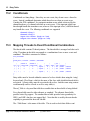
15.3 Mapping
..............................................................................................................
Threads to Event/Conditional Combinations
102
15.4 The
..............................................................................................................
Alternate Entry Table
103
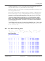
15.5 The
..............................................................................................................
standard entry table
104
15.6 Entry
..............................................................................................................
Error Handler
105
Part 16 Writing Optimize-Able Assembly
107
16.1 Functions
..............................................................................................................
and Function Calls
107
16.2 Writing
..............................................................................................................
the Return Address Register
107
16.3 The
..............................................................................................................
Dispatch Operation
108
16.4 MAC
..............................................................................................................
operations
108
16.5 Variable
..............................................................................................................
Names
108
page 8, Assembler Reference Manual
Assembler Reference Manual
Assembler Reference Manual, page 9
page 10, Assembler Reference Manual
1. Introduction
1
Introduction
The story of this ETEC Assembler is long and convoluted. The original TPU developed by
Motorola back in the late 1980’s employed an unusual syntax that was difficult to write and
difficult to understand.
The ‘Freescale’ eTPU syntax was developed along with the eTPU itself in the early
2000’s and is based on that original TPU syntax.
ASH WARE developed a ‘Verbose’ syntax in which the primary motivation was
readability. The thinking was that eTPU coders would develop their code in ‘C’ and would
neither use nor learn Freescale’s rather obtuse assembly language syntax. The ‘verbose’
syntax was developed primarily to be readable so that the ‘C’ coder could view and
understand the syntax from within the Simulator’s source code window (in mixed ‘C’/
Assembly mode).
Quite a bit of eTPU assembly has been written using the ‘Freescale’ syntax. A small
number of these applications have been written entirely in assembly and the rest employ a
mix of regular ‘C’ with some inline assembly.
In developing it’s ETEC compiler ASH WARE needed to support this existing code base,
and therefore decided to support the ‘Freescale’ assembly syntax instead of it’s own
‘Verbose’ syntax.
A significant barrier to support of the existing ‘Freescale’ syntax is its lack of
documentation and inconstancy over time. The task of supporting the existing syntax is
Freescale Syntax
(C) 2007-2015
Assembler Reference Manual, page 11
1. Introduction
extremely difficult and (to say the least) far from satisfying.
Having said that, ASH WARE’s strong bias towards supporting a strict syntax has been
tempered by our requirement to support the existing code base. We have therefore chosen
the following approach. We have chosen to support and document a single consistent
syntax both in this manual and in the assembler itself. This syntax has been chosen such
that it is supported both by our own assembler and (as far as we can determine) by more
recent versions of the Freescale syntax.
In the one or two cases where the existing syntax is flat-out wrong, it is simply not
supported. Instead, a new and correct syntax has been developed, and use of the wrong
syntax results in an error message in which the new and correct syntax is shown.
But in some cases ASH WARE supports additional syntax varieties where the syntax
variation has broad use. We generally discourage use of these syntax variations and
wherever possible generate warnings when this non-standard syntax is encountered. It is
strongly recommended that users migrate their assembly to the syntax documented within
this manual.
page 12, Assembler Reference Manual
(C) 2007-2015
Freescale Syntax
2. Command Line Options
2
Command Line Options
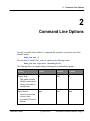
Type the executable name with the -h command line parameter to generate a list of the
available options.
ETEC_asm.exe –h
The assembler is called ETEC_asm.exe, and it has the following format:
ETEC_asm.exe <options> <AssemblyFile>
The following table is a complete listing of all supported command line options.
Setting
Option
Default
Example
Display Help
-h
Off
-h
-man
Off
-man
This option overrides
all others and when it
exists no assembly is
actually done.
Open Manual
Opens the electronic
version of this
Assembler Reference
Manual.
Freescale Syntax
(C) 2007-2015
Assembler Reference Manual, page 13
2. Command Line Options
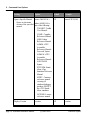
Setting
Option
Default
Example
Open a Specific Manual
-man=<MANUAL>
Off
-man=ETPUCIM
Off
-version
Opens an electronic
where MANUAL is
version of the specified one of the following:
manual.
TOOLKIT: Toolkit
User Manual.
COMP: Compiler
Reference Manual
LINK: Linker
Reference Manual.
ASMFS: eTPU
Assembler
Reference Manual Freescale Syntax.
ASMAW: eTPU
Assembler
Reference Manual ASH WARE
Syntax.
ETPUSIM: StandAlone eTpu
Simulator Reference
Manual.
MTDT: Common
reference manual
covering all
simulator/debugger
products EXCEPT
the eTPU StandAlone simulator.
LICENSE: License
reference manual
Display Version
page 14, Assembler Reference Manual
-version
(C) 2007-2015
Freescale Syntax
2. Command Line Options
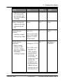
Setting
Option
Default
Example
-license
Off
-license
Console Message
Verbosity
-verb=<N>
5
-verb=9
Console Message
Suppression
verbSuppress=<TYPE
>
Off
-verbSuppress=
SUMMARY
Displays the tool name
and version number
and exits with a nonzero exit code without
assembling.
Display Licensing Info
Outputs the licensing
information for this
tool.
where N can be in the
Control the verbosity
range of 0 (no console
of the message output. output) to 9 (verbose
message output).
Suppress console
messages by their
type/class. Multiple
types can be specified
with multiple –
verbSuppress options.
where TYPE can be:
BANNER : the
ETEC version &
copyright banner.
SUMMARY : the
success/failure
warning/error count
summary line
WARNING : all
warning messages
ERROR : all error
messages (does not
affect the tool exit
Freescale Syntax
(C) 2007-2015
Assembler Reference Manual, page 15
2. Command Line Options
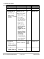
Setting
Option
Default
Example
ETEC
-msgStyle=MSDV
code)
Console Message Style
msgStyle=<STYLE>
Controls the style of
where STYLE can be:
the error/warning
- ETEC : default
output messages,
primarily for integration ETEC message style.
with IDEs
- GNU : output
messages in GNUstyle. This allows the
default error parsers
of tools such as
Eclipse to parse
ETEC output and
allow users to click
on an error message
and go to the
offending source line.
- MSDV : output in
Microsoft Developer
Studio format so that
when using the
DevStudio IDE
errors/warnings can
be clicked on to bring
focus to the problem
source code line.
Warning Disable
Disable a specific
assembly warning via
its numerical identifier.
Error on Warning
Turn any warning into
page 16, Assembler Reference Manual
Off (all
warnDis=<WARNID> warnings
enabled)
-warnDis=33243
-strict
-strict
Off
Note that this
(C) 2007-2015
Freescale Syntax
2. Command Line Options
Setting
an assembly error.
Option
Default
Example
None
-
changed from warnError which is
being deprecated
<AsmFile>
Name of the assembly
file to assemble
Output File To Produce
-out=<BaseFileName> <AsmFile>.
eao
-out=MyOutputFile
-syntax=<eSyn>
FS
-out=AW
ETPU1
-target=ETPU2
Object file name
Assembly Syntax
where eSyn is the
assembly syntax which
can be either AW
(ASH WARE) or FS
(Freescale.)
Target Selection
Select the destination
processor for the
compilation.
-target=<TARGET>
where TARGET can
be:
ETPU1 : compile
for the baseline
eTPU processor.
ETPU2 : compile
for the eTPU2
processor version.
Freescale Syntax
(C) 2007-2015
Assembler Reference Manual, page 17
2. Command Line Options
2.1
File Naming Conventions
.STA
.EAO
.ELF
.h
2.2
Structured eTPU assembly file suffix
eTPU Annotate Object file suffix
Elf/Dwarf file suffix
"C" language style header file suffix
The Build Process
An assembly file is assembled to create an eTPU Annotated Object file.
ETEC_asm.exe
MyAsmFile.sta
If the assembly fails then no object file is created, and any pre-existing object file with that
name is deleted.
On or more object files are linked to generate a generic executable image file. The
following shows linking two object files together, one of which was generated by the
assembler and one of which was generated by the compiler.
ETEC_link.exe
MyAsmFile.eao
MyAsmC.eao
If the linking fails then no executable file is created and any pre-existing executable file is
deleted.
See the ETEC reference manual for a complete listing of all the Compiler, Assembler, and
Linker command line options.
page 18, Assembler Reference Manual
(C) 2007-2015
Freescale Syntax
3. Preprocessing and Directives
3
Preprocessing and Directives
This section covers preprocessing and directives.
3.1
Text Replacement using #define
Simple text replacement is supported via a C-style #define as follows.
#define SOME_ADDRESS sprm0x41
ram diob <- SOME_ADDRESS.
// This is the same as the following
ram diob <- sprm0x41.
The text replacement can span multiple lines using the continuation character, '\', as
follows.
#define A_ValuE 10 \
+ 2 \
- 3;
3.2
File Inclusion
One file can include another file using the C-style #include directive as follows.
#include "MyHeaderFile.h"
Freescale Syntax
(C) 2007-2015
Assembler Reference Manual, page 19
3. Preprocessing and Directives
3.3
Automatically-Generated Directives
One of the following target define directives is automatically-generated. Note that the
target is set by the command line options.
#define
#define
__TARGET_ETPU1__
__TARGET_ETPU2__
1
1
These are handy when generating code conditionally, such as the following.
#ifdef __TARGET_ETPU2__
// Test FLAG 1 (eTPU2 and later only) ...
seq if flag1 == 0 then goto
_Error_handler_Flag1NotSet, flush.
alu p7_0 = p7_0 low| 0x40.
_Error_handler_Flag1NotSet:
#endif // __TARGET_ETPU2__
3.4
Comments
Both C and C++ style comments are supported, as follows.
// This is a C++ style comment
/*
This is a C comment
*/
3.5
Verify Version
A #pragma to verify that the proper version of the ETEC Assembler is being used to
generate a particular piece of source code is available.
#pragma verify_version <comparator>, “<version string>”,
“<error message>”
When such a #pragma is processed by the compiler, a comparison is performed using the
specified <comparator> operation, of the ETEC Assembler’s version and the specified
“<version string>”. The supported comparators are:
GE – greater-than-equal
GT – greater-than
page 20, Assembler Reference Manual
(C) 2007-2015
Freescale Syntax
3. Preprocessing and Directives
EQ – equal
LE – less-than-equal
LT – less-than
The specified version string must have the format of “<major version number>.<minor
version number (2 digits)><build letter (letter A-Z)>”. The last token of the #pragma
verify_version is a user-supplied error message that will be output should the comparison
fail.
For example, if the compiler were to encounter the following in the source code
#pragma verify_version GE, "1.20C", "this build requires
ETEC version 1.20C or newer"
The ETEC Assembler will perform the test <ETEC Assembler version> >= “1.20C”, and
if the result is false an error occurs and the supplied message is output as part of the error.
With this particular example, below are some failing & passing cases that explain how the
comparison is done
// (equal to specified “1.20C”)
ETEC Assembler version = 1.20C
=> true
// (major version is less than that specified)
ETEC Assembler version = 0.50.G
=> false
// (minor version 21 greater than that specified)
ETEC Assembler version = 1.21A
=> true
// (build letter greater than that specified)
ETEC Assembler version = 1.20E
=> true
3.6
Disabling Optimization in Chunks of Code
If it is desired to disable optimization on a section of code, the pragmas
#pragma optimization_disable_start
and
#pragma optimization_disable_end
can be used to do so. All optimizations are disabled within the specified region, so this
feature should be used with care.
Freescale Syntax
(C) 2007-2015
Assembler Reference Manual, page 21
3. Preprocessing and Directives
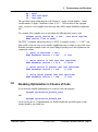
3.7
Disabling Optimizations by Type
The ETEC optimizer operates by applying a series of optimizations to the code, thereby
reducing code size, improving worst case thread length, reducing the number of RAM
accesses, etc. Although these optimizations are generally disabled en-masse from the
command line using -opt-, it is also possible (but hopefully never) required to individually
disable specific optimizations within a source code file using the following option.
#pragma disable_optimization <Num>
This disables optimization number, <num>, in entire translation unit(s) in which the source
code or header file is found.
The optimization numbers are not documented and must be obtained directly from ASH
WARE. Note that the purpose of disabling specific optimizations is to work-around
optimizer bugs in conjunction with ASH WARE support personnel.
3.8
Atomicity Control
In many cases multiple sub-instructions can be fit into a single opcode. One of the most
powerful optimizations is to gather multiple such sub instructions into a single opcode, but
occasionally (actually infrequently) there are dependencies between the sub-instructions
such that in order to function properly, the multiple sub-instructions must be fit into a single
opcode. The classic example of this is the clearing and enabling of the Match Enable
Register (MRL.) The following atomic directive instructs the optimizer (if enabled) to
retain these two sub-instructions in the same opcode.
// Keep these two sub-instructions
// in the same opcode
#pragma atomic
chan clr_mrla, write_erta.
3.9
Optimization Boundary
In some cases there may be an ordering dependency that must be enforced. Say a buffer
gets updated, followed by the setting of a flag that indicates to the host that the buffer has
been updated. It is important that the buffer update completes prior to flag getting set,
otherwise the host might read the buffer prior the eTPU completing the updated. This
ordering dependency is enforced as follows.
// The first RAM operation
// MUST occur prior to the second
page 22, Assembler Reference Manual
(C) 2007-2015
Freescale Syntax
3. Preprocessing and Directives
ram p -> by diob++.
alu p = 1.
#pragma optimization_boundary_all
ram p -> prm0x2D.
3.10
Thread Length Verification (WCTL)
The verify_wctl pragma are used for the following:
No thread referenced from a Class or eTPU Function (including both member
threads and global threads) exceed a specified number of steps or RAM accesses.
A specific thread does not exceed a specified number of steps or ram accesses.
For classes with multiple entry tables, the worst-case thread of any entry table can
be specified (currently only available in ETEC mode.)
A global ‘C’ function or member ‘C’ function does not exceed a specified number
of steps or ram accesses.
The syntax is as follows:
#pragma verify_wctl <eTPUFunction>
steps <MaxRams> rams
#pragma verify_wctl <eTPUFunction>::<Thread>
steps <MaxRams> rams
#pragma verify_wctl
<MaxRams> rams
#pragma verify_wctl
<MaxRams> rams
#pragma verify_wctl
<MaxRams> rams
#pragma verify_wctl
<MaxRams> rams
<MaxSteps>
<MaxSteps>
<Class>
<MaxSteps> steps
<Class>::<Thread>
<MaxSteps> steps
<Class>::<Table>
<MaxSteps> steps
<Class>::<CFunc>
<MaxSteps> steps
#pragma verify_wctl <GlobalCFunc>
<MaxRams> rams
<MaxSteps> steps
Note that global threads must be scoped with a class that references it. In other words,
say there is a common global thread referenced from several different classes entry tables.
The following syntax would be required where the class name is the name of one class
that references the global thread.
Freescale Syntax
(C) 2007-2015
Assembler Reference Manual, page 23
3. Preprocessing and Directives
#pragma verify_wctl <Class>::<GlobalThread>
steps <MaxRams> rams
<MaxSteps>
Some called functions (‘C’ functions or member functions) may have routes that return to
the caller but also may end the thread. In such causes the verify_wctl acts on the longer
of these two.
The WCTL analyses assumes that called functions are well-behaved in terms of call-stack
hierarchy. For instance, if Func() calls FuncB() and FuncB() calls FuncC(), a return in
FuncA() will go to the location in FuncB() where the call occurred. Additionally, a return
within FuncB() will then return to Func() where that call occurred. In order for this to
occur, the rar register must be handled correctly, which is guaranteed in ETEC compiled
code, as long as inline assembly does not modify the RAR register. It is also guaranteed in
assembly as long as RAR save-restore operations are employed in a function’s prologue
and epilogue.
The WCTL calculations remain valid even when a thread ends in a called function.
The following are examples uses of verify_wctl:
// Verify WCTL of a global function
#pragma verify_wctl mc_sqrt 82 steps 0 rams
// Verify WCTL of a specific thread within a class
#pragma verify_wctl UART::SendOneBit
25 steps 7 rams
// Verify WCTL of the longest thread within an entire class
#pragma verify_wctl UART 30 steps 9 rams
3.11
Forcing the WCTL
In some cases a thread, eTPU function, or an eTPU class may not be able to be analyzed.
This can occur when multiple loop are encountered or when the program flow is too
convuluted for a static analyses. In these cases, the maximum WCTL can be forced using
the following #pragma.
#pragma force_wctl <Name> <max_steps> steps <max_rams> rams
An example of this is the square root function in the standard library used in Freescale's set
4. This has two loops where the maximum number of times through each of the loops is
inter-dependent, and this complicated loop limit relationship is well, not supported ETEC's
worst case thread length analyses. The following #pragma is used to establish this limit
#pragma force_wctl
page 24, Assembler Reference Manual
mc_sqrt
82 steps
(C) 2007-2015
0 rams
Freescale Syntax
3. Preprocessing and Directives
3.12
Excluding a thread from WCTL
A thread can be excluded from the WCTL calculation of a function. This is normally used
for initialization or error handling threads that in normal operation would not contribute to
the Worst Case Latency (WCL) calculation. The format is as follows:
#pragma exclude_wctl <eTPU Function>::<ExcludedInitThread>
For example the following excludes a UART's initialization thread from the worst case.
#pragma exclude_wctl UART::init
3.13
Loop Iteration Count
Loops in eTPU code are generally not a good programming practice because the eTPU is
an event/response machine in which long threads (such as those caused by loops) can
prevent the quick response time to meet many applications’ timing requirements.
However, loops are occasionally required, and are therefore supported by the optimizer.
But there is no way to analyze the worst case thread length for threads that contain loops,
and therefore loops prevent analyses unless loop bounding iteration tags are added.
#pragma wctl_loop_iterations <max_loop_count>
<Some Loop>
3.14
Memory Size (Usage) Verification
The memory usage verification pragma, verify_memory_size, allows the user to verify at
build time that their memory usage meets size requirements. Memory usage is verified on
a memory section basis. The pre-defined (default) memory sections are named &
described below:
GLOBAL_VAR
- user-declared global variables
GLOBAL_SCRATCHPAD - local variables allocated
out of global memory (scratchpad)
Freescale Syntax
GLOBAL_ALL
- all global memory usage
ENGINE_VAR
- user-declared variables
in engine-relative memory space
(eTPU2 only)
(C) 2007-2015
Assembler Reference Manual, page 25
3. Preprocessing and Directives
ENGINE_SCRATCHPAD - local variables allocated
out of engine-relative memory
(engine scratchpad, eTPU2 only)
ENGINE_ALL
- all engine-relative memory usage
(eTPU2 only)
STACK
- maximum stack size
User-defined memory sections can also be verified. Currently only channel frames are
supported – these are verified by specifying the appropriate eTPU class or function name.
The pragma has the following syntax options
#pragma
#pragma
#pragma
#pragma
verify_memory_size
verify_memory_size
verify_memory_size
verify_memory_size
<memory section> <MaxSize> bytes
<memory section> <MaxSize> words
<eTPU class/function> <MaxSize> bytes
<eTPU class/function> <MaxSize> words
The maximum allowable size for a given memory section (or channel frame) can be
specified in bytes or words (4 bytes/word). If the actual size of the memory section
exceeds MaxSize, the linker issues an error.
This pragma is available in both the Assembler and Compiler.
3.15
Same Channel Frame Base Address
When multiple channels use the same channel frame base address, there is no need to reload channel variables when the channel is changed. In certain cases this can result in
improvements in code speed and size. The following tells the compiler that the CPBA
register value will be the same for all channel changes of within the specified function.
#pragma same_channel_frame_base <etpu_function>
The etpu_function argument is the name of an eTPU function, C function, or eTPU class.
An example where this is useful is in the Freescale set 1 SPI function, which controls
multiple channels that all share the same channel frame base address. The SPI function
can compile tighter when the ETEC tools know about this, which can be done by adding:
#pragma same_channel_frame_base SPI
page 26, Assembler Reference Manual
(C) 2007-2015
Freescale Syntax
3. Preprocessing and Directives
3.16
Coherency
The eTPU contains a Coherent Dual Parameter Controller (CDC) that allows coherent
transfers to and from the DATA RAM of parameter pairs. The problem is that the
optimizer may eliminate, re-order or otherwise change these accesses in such a way that
they are no longer coherent. The following syntax is used to ensure that the optimizer
retains coherency.
#pragma coherent_begin
ram p
<- ChanVar1.
ram diob <- ChanVar5.
#pragma coherent_end
This results in the following action by the optimizer.
* The accesses will not be eliminated
* The accesses will remain on opcodes that are always executed sequentially
* There will always be a non-RAM on the preceding opcode. (If required, the optimizer will
NOP to make this so.)
3.16.1 Coherency Notes
For the purposes of coherency, the optimizer is a separate and distinct portion of the linker.
The actions taken by the optimizer to ensure coherency are therefore only taken if the
optimizer is enabled.
In other words, if optimizations are disabled, the optimizer cannot make non-coherent
accesses coherent, and you are therefore required to ensure that the un-optimized
assembly is intrinsically coherent.
3.17
Format Specification
A specific format can be forced using the #pragma format directive. Assembly will fail if
the opcode cannot be fit into the specified format.
#pragma format "FormatB2"
The following is an example:
#pragma format "FormatB2"
ram p <- prm0xD.
Freescale Syntax
(C) 2007-2015
Assembler Reference Manual, page 27
3. Preprocessing and Directives
3.18
Verifying Opcode Generation
Generation of a specific opcode can be guaranteed using the #pragma verify_opcode
directive as follows.
ram diob <- sprm0x7D.
#pragma verify_opcode 0x9FEFFF1F 0xFFFFFFFF
Note that the #pragma verify comes after the opcode. The second number is a mask
applied to both the opcode that is verified and to the bit-pattern that is being verified.
Clearing bits in the mask essentially disables those particular bits from being verified. An
example of when the mask is handy is a function call where the destination address is
indeterminate during assembly.
3.19
Forcing a Specific opcode
A particular opcode bit-pattern can be forced using the following pattern.
%hex 0xBFEFFB7F.
// Above is the same as below, just hard-coded
ram p <- #0.
#pragma verify_opcode 0xBFEFFB7F 0xffffffff
3.20
Called Functions
The user is tasked with correctly bounding code that forms a called function, as follows.
#pragma mimic_c_func_start
MySimpleFunc:
// Do something (function body)
alu diob = diob + 1.
seq return, flush.
#pragma mimic_c_func_end
3.21
Return Address Save/Restore
When one called function calls a second called function a two-deep function call is
generated in which the return address register from the calling function must be saved prior
to the call and restored following the call.
Saving and restoring of the Return Address Register (RAR) can cause un-resolvable
page 28, Assembler Reference Manual
(C) 2007-2015
Freescale Syntax
3. Preprocessing and Directives
program-flow issues with the analyzer/optimizer. In order for optimization and analyses to
be allowed, the save/restore operations (which are supported by the analyzer/optimizer)
must be tagged using the #pragma start/end save/restore <regionName> tags. This is done
as shown in the following example.
//----------------------------------#pragma mimic_c_func_start
OneDeepFunc:
//----------------------------------// Save the return address
#pragma start save rar_chunk "OneDeepFunc_epop"
// Save the ReturnAddr register
alu
diob = rar.
#pragma end save rar_chunk
"OneDeepFunc_epop"
//----------------------------------seq call TwoDeepFunc, flush.
//----------------------------------// Restore the ReturnAddr register
#pragma start restore rar_chunk
"OneDeepFunc_epop"
alu rar = diob.
#pragma end restore rar_chunk
"OneDeepFunc_epop"
//----------------------------------seq return, flush.
#pragma mimic_c_func_end
//----------------------------------//----------------------------------#pragma mimic_c_func_start
TwoDeepFunc:
alu p = p + 1.
seq return, flush.
#pragma mimic_c_func_end
//-----------------------------------
Freescale Syntax
(C) 2007-2015
Assembler Reference Manual, page 29
3. Preprocessing and Directives
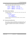
3.22
Dispatch List
The ‘dispatch’ instruction, while very powerful, makes code nearly impossible to analyze or
optimize because the ultimate destination is not known at link time (note that ‘dispatch’ is
an indexed ‘goto’ or ‘call’ in which the next PC address is the current PC address plus an
offset specified by the p31_24 register.)
For this reason, use of a dispatch prevents both optimization and analyses unless tags are
inserted into the code that ‘tells’ the optimizer all possible dispatch destinations. Failure to
properly identify all possible dispatch destinations with these tags can result in improper
optimization.
The following example illustrates use of the dispatch_list_start and dispatch_list_end tags.
A #pragma dispatch_list_start tag immediately precedes the dispatch opcode and is
followed by a comma-separated list of labels (dispatch destinations.) Following the final
dispatch label, there must be a #pragma dispatch_list_end. All listed labels must be
between the start/end tags. Note that since the dispatch only generated positives offsets,
all the labels must follow the start tag. There may be multiple opcodes between the labels.
// Load the current state
// into the p31_24 register
ram p31_24 <- CurrentState.
#pragma dispatch_list_start Dst1, Dst2, Dst3, Dst4
seq dispatch_goto, flush.
Dst1:
// p_31_24 == 0
seq goto State0, flush.
Dst2:
// p_31_24 == 1
seq goto State1, flush.
Dst3:
// p_31_24 == 2
seq goto State2, flush.
Dst4:
// p_31_24 == 3
seq goto State3,flush.
#pragma dispatch_list_end
page 30, Assembler Reference Manual
(C) 2007-2015
Freescale Syntax
4. Notation and Syntax
4
Notation and Syntax
Decimal, hexadecimal, and binary notations are supported, as follows. All of the numbers
shown below yield the same weighting of 85 decimal in their load of the ‘p’ register.
alu p = 0x55.
alu p = 0b01010101.
alu p = 85.
Freescale Syntax
// Hexadecimal Notation
// Binary Notation
// Decimal notation
(C) 2007-2015
Assembler Reference Manual, page 31
page 32, Assembler Reference Manual
5. Data Memory Packing
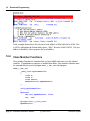
5
Data Memory Packing
Data packing is not guaranteed and may change as new assembler and linker versions are
released. All packing information should be determined using the auto-define capability
which places data address information into header files for inclusion into both host side “C”
code as well as eTPU Command Script files. If you are using a host-side language besides
“C” please contact ASH WARE so that we can provide the required interface information
for you language.
Freescale Syntax
(C) 2007-2015
Assembler Reference Manual, page 33
page 34, Assembler Reference Manual
6. The Register Set
6
The Register Set
The eTPU contains a large number of registers many of which have specific purposes.
The registers are listed by function in this section.
6.1
The “Big 4” Registers
The following registers constitute the best and most commonly accessed registers.
alu
alu
alu
alu
6.2
p
p
p
p
=
=
=
=
p.
diob.
sr.
a.
//
//
//
//
‘p’ register on A-Bus-Source
‘diob’ register on A-Bus-Source
‘sr’ register on A-Bus-Source
‘a’ register on A-Bus-Source
The P Register
The P register is one of the “big 4” as mentioned previously. It supports access of its 32,
24, 16, and 8 bit components, as follows.
// 24-Bit access (native)
alu p = p.
alu p = p23_0. // Same as above, just more explicit.
// 8-bit access of any of the 4 byte
alu p = p7_0.
Freescale Syntax
(C) 2007-2015
Assembler Reference Manual, page 35
6. The Register Set
alu p = p15_8.
alu p = p31_24.
alu p = p23_16.
// 32-bit access (Load/store with DATA RAM only)
ram p31_0 <- MyInt32.
// 16-bit access (Least common)
alu p = p15_0.
alu p = p31_16.
6.3
The Scratchpad Registers
The following registers are considered “scratchpad” because they are less well supported
by the instruction set. For instance, these are not available on the execution unit’s “BBus.”
// ‘b’ register on A-Bus-Source
alu p = b.
// ‘cReg’ register on A-Bus-Source
//
!!! CASE SENSITIVE !!!
alu p = c.
// ‘d’ register on A-Bus-Source
alu p = d.
Due to a strange web of lies and half-truths, the ‘c’ register is case sensitive. This allows
the ‘c’ register (lowercase) to be differentiated from the ‘C’ flag (uppercase.)
6.4
Global Timebase Registers
Although these registers are can be both read and written by the execution unit, they serve
as the global timebases. The TCR1 counter generally is clocked from the system clock
such that it increments and a specific rate. The TCR2 counter is often used in conjunction
with the special angle mode hardware to increment and an engine angle proportional rate.
// ‘tcr1’ register on A-Bus-Source
alu p = tcr1.
// ‘tcr2’ register on A-Bus-Source
alu p = tcr2.
page 36, Assembler Reference Manual
(C) 2007-2015
Freescale Syntax
6. The Register Set
6.5
The ‘Chan’ (channel) Register
The channel register is written by the scheduler prior to the beginning of each thread, with
the channel number that is being serviced. It can be read during the thread to determine
which channel number is being serviced. It can be written during the thread to either
update the event registers with (potentially) new capture values or to change the channel
upon which most of the channel commands operate. The ChanBase register contains the
address of the channel frame for the active channel. This register can be read, but not
written. It is handy for accessing the channel variables of a different channel without
having to actually change the channel number.
// ‘chan’ register on A-Bus-Source
alu p = Chan.
Re f: CPBA
6.6
Channel Base Address Register
The ChanBase register contains the address of the channel frame for the active channel.
This register can be read, but not written. It is handy for accessing the channel variables
of a different channel without having to actually change the channel number.
// ‘chan_base’ register on A-Bus-Source
alu p = chan_base.
Re f: CPBA
6.7
Engine Base Address Register
This register is only in eTPU2.
The engine base register is a read-only for the eTPU. It contains the value written in the
Engine Control Register’s Engine Relative Base Address Field (ECR.ERBA.) Note that
ECR.ERBA is written by the host CPU. The value read by the eTPU is the base address
(in bytes) of the engine relative data.
// ‘engine_base’ register on A-Bus-Source
alu p = engine_base.
Re f: ECR.ERBA
Freescale Syntax
(C) 2007-2015
Assembler Reference Manual, page 37
6. The Register Set
6.8
Event Registers
There are two event registers, one for each action unit. At the beginning each thread, the
event register is loaded with the capture value from the channel being serviced. During the
thread, match values can be loaded into this register and transferred to a channel’s match
registers. If the channel register is written, then new capture values are re-loaded into the
event registers
alu p = erta.
alu p = ertb.
6.9
// ‘erta’ register on A-Bus-Source
// ‘ertb’ register on A-Bus-Source
Channel to Channel Linking Register
The link register allows one channel to cause a thread to occur on another channel. This is
accomplished by writing the link register with the channel number of the channel where the
link event will occur. Note that this channel is write only such that it cannot be written.
// cause a ‘link’ thread on channel 5
#define LINK_CHAN 5
alu link = LINK_CHAN.
One consequence of this is that the channel from which a link occurred cannot be
determined directly through the instruction set.
6.10
Multiply-Accumulate (MAC) Registers
The following registers are used for multiply-accumulate.
// ‘macl’ register on A-Bus-Source
alu p = macl.
// ‘mach’ register on A-Bus-Source
alu p = mach.
// ‘mac’ register as MDU destination
mdu diob multu sr.
Some MAC operations access both the high and low MAC registers, the mac keyword is
used to indicate this in the verbose syntax.
page 38, Assembler Reference Manual
(C) 2007-2015
Freescale Syntax
6. The Register Set
6.11
Angle Mode Registers
These registers are used as part of angle mode which is when the tcr2 counter is clocked
at an angle-proportional rate. The tick rate register (TRR) establishes the number of tcr1
ticks must occur for each tcr2 to occur. In other words, it is the divide down from tcr1 to
tcr2. The tooth program register (TPR) contains a several bit-packed fields that used to
configure angle mode.
// Tooth Program register on A-Bus-Source
alu p = tpr.
// Tick Rate register on A-Bus-Source
alu p = trr.
6.12
Program Flow Registers
The return address register (RAR) contains the return address following a call. It can be
read and written, thereby supporting a call stack. The program counter cannot be directly
read or written, but is used as part of the dispatch call syntax which is why it is listed here.
// Program counter used in dispatch
seq dispatch_call,flush.
// ‘ReturnAddr’ register on A-Bus-Source
alu p = rar.
Freescale Syntax
(C) 2007-2015
Assembler Reference Manual, page 39
page 40, Assembler Reference Manual
7. Opcode and Sub-Instruction Structure
7
Opcode and Sub-Instruction
Structure
This section covers the assembler's opcode and sub-instruction structure.
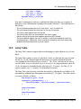
7.1
Sub Instruction Types
Each ETPU opcode is split into one of the following four sub-instruction types.
ram
seq
alu
chan
7.2
Sub-Instruction groups
Multiple sub-instructions of the same type may be grouped together by separating the subinstructions with commas. Sub-instruction groups that contain one or more sub-instructions
are terminated by a semicolon, as follows.
chan clr_mrla, clr_mrlb.
Freescale Syntax
(C) 2007-2015
Assembler Reference Manual, page 41
7. Opcode and Sub-Instruction Structure
7.3
Opcode Termination
Opcodes are terminated by a period. Each opcode may contain multiple sub-instruction
groups. All groups except the last are terminated by a semicolon
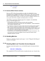
chan clr_mrla, clr_mrlb.
seq if z == 1 then goto startTest, flush.
7.4
The ‘No-Operation’ (NOP)
A nop is used to generate an opcode that performs no operation.
nop.
page 42, Assembler Reference Manual
(C) 2007-2015
Freescale Syntax
8. Parameter RAM Accesses
8
Parameter RAM Accesses
This section describes the various capabilities available via the PRAM sub-instruction
fields. Note that most, but not all, of these capabilities involve reading and writing PRAM.
Non-- PRAM capabilities include clearing to zero the P and diob registers, auto-increment
and auto-decrement of the diob register, and semaphore locking and freeing.
Sub instructions: RW, PD, RSIZ, ZRO , STC, AID[7:0], AID[6:0], and AID[2:0],
8.1
Accessing Data at a Specific Address
Data can be read and written at a specific address using global addressing, as follows.
// Read the 32-bit value
// at address 40h into register P
ram p31_0 <- sprm0x40.
Global PRAM can be written using the following format.
// Write the 24-bit value from the diob register
// to address 41h
ram diob -> sprm0x41.
Fie ld: AID[7:0]
Freescale Syntax
(C) 2007-2015
Assembler Reference Manual, page 43
8. Parameter RAM Accesses
8.2
Accessing a Channel's Data
Each channel has its own base address. A channel's data is accessed relative to this base
address using channel relative accesses as follows.
// Read a channel's relative 32-bit word
// into the P_31_0 register
ram p31_0 <- prm0x2C.
// Write channel data from the diob register
ram diob -> prm0x2D.
Fie ld: AID[6:0] and AID[2:0]
8.3
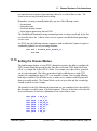
Accessing an Engine’s Data
Each engine has its own block of ‘engine’ data. This engine data is accessed relative to
the engine-relative-base address field in the Engine Configuration Register (ECR.ERBA.)
Engine data is accessed as follows
// Read engine relative 32-bit word
// into the P_31_0 register
ram p31_0 <- eng0x2C.
// Write channel data from the diob register
ram diob -> eng0x2D.
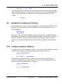
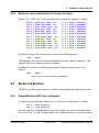
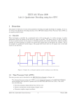
Note that when accessing engine data, the actual (byte) address is as follows
ByteAddress = (ECR.ERBA << 9) + ([AID_6_0] << 2);
This forms an address from the ECR.ERBA and AID_6_0 as follows.
Value
0
0
0
Bit
15
14
13
ECR.ERBA
12
11
10
AID_6_0
9
8
7
6
5
4
3
2
X
X
1
0
Fie ld: AID[6:0] (e ngine )
page 44, Assembler Reference Manual
(C) 2007-2015
Freescale Syntax
8. Parameter RAM Accesses
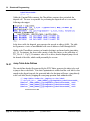
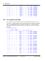
8.4
Address Nomenclature
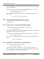
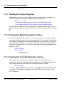
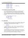
All addresses are specified using the nearly universal byte mode. For instance, consider
the following memory dump.
The following read puts 0x6C7D4C85 into the P register.
ram p31_0 <- sprm0x0.
The following read puts 0x3CB12500 into the P register.
ram p31_0 <- sprm0x4.
8.5
diob Register Relative Accesses
The diob register can be used as a pointer for - PRAM accesses, as follows.
// Read the value from PRAM
// pointed to by the diob register
// into the P register
ram p <- by diob.
ram p -> by diob++.
// Post Increment
ram p -> by --diob.
// Pre-decrement
Fie ld: STC
8.6
Clearing Parameter RAM and Registers
Data RAM and the P or diob registers can be cleared (set to zero), as follows. Note that
when data RAM is being cleared, the size information is required as part of the opcode.
// Clear the diob register
ram diob <- #0.
// Clear some Channel RAM
ram #0 -> prm0x20, p_access_8.
ram #0 -> prm0x21, p_access_24.
ram #0 -> prm0x20, p_access_32.
Freescale Syntax
(C) 2007-2015
Assembler Reference Manual, page 45
8. Parameter RAM Accesses
// Clear some Engine RAM
ram #0 -> eng0x20, p_access_8.
ram #0 -> eng0x21, p_access_24.
ram #0 -> eng0x20, p_access_32.
8.7
diob Pre-Decrement and Post-Increment
The diob register can be pre-decremented, as follows. Note that the address used is the
decremented value of the diob register.
// Write the value from the P register
// into the PRAM address specified
// by the diob register minus 4.
// The diob register retains the decremented value
ram p <- by --diob.
The diob can be post-incremented, as follows. Note that the address used is the diob
register prior to being incremented
// Read the value from PRAM
// pointed to by the diob register
// into the P register
// The diob register is then incremented.
ram p <- by diob++.
The decrement and increment are also available with the zero construct, as follows.
// Clear the P register,
// increment the diob register by 4.
ram p <- #0, by diob++.
// Clear a pram word using diob as a pointer,
// pre-decrement the diob register by 4.
ram #0 -> by diob++, p_access_24.
Fie ld: STC
8.8
Operation Size
The operation size is specified similarly to a C cast, as follows.
// Write an 8-bit value
ram p31_24 -> by --diob.
// Write a 24-bit value
ram p23_0 -> by --diob.
// Write a 32-bit value
page 46, Assembler Reference Manual
(C) 2007-2015
Freescale Syntax
8. Parameter RAM Accesses
ram p31_0 -> by --diob.
Note that despite the nomenclature, all pre-decrement and post-increment operations add/
subtract the diob register by 4. Note also that an 8-bit access affects only the upper 8 bits
(nibble) of the 32-bit location. A 24-bit access affects the lower 24-bits of the 32-bit
location.
Fie ld: RSIZ.
8.9
Semaphore Locking and Freeing
Four semaphores are provided. These semaphores are locked and freed as follows. Note
that whereas each semaphore is locked individually, a single sub-instruction frees any
locked semaphore.
ram lock_g2.
ram free_g.
Wherever possible semaphores should be avoided as they provide a mechanism for nondeterministic execution speed. Simple deterministic algorithms can generally be employed
in lieu of semaphores. But hey, if you do decide to use semaphores (drink, use drugs,
smoke, etc.) remember to unlock them as soon as possible! And please, don't drink and
drive.
8.10
Taking a Variable’s Address
A variables address can be loaded into a register. For instance, if in the following example,
GlobalVar24 is at address 0x11, then the diob register is loaded with a 0x11.
int24 GlobalVar24;
// < ... >
alu diob = GlobalVar24.
The address of a channel variable can also be taken. For instance, in the following
example, if ChanVar24 is at an address offset of 0x39 from the channel parameter base
address, then a 0x39 is loaded into the ‘B’ register.
int24 ChanVar24;
// < ... >
alu b = ChanVar24.
Freescale Syntax
(C) 2007-2015
Assembler Reference Manual, page 47
page 48, Assembler Reference Manual
9. Arithmetic Logic Unit (alu)
9
Arithmetic Logic Unit (alu)
The ETPU has a Harvard architecture style Arithmetic Logic Unit (alu.) All alu
commands begin with an A-bus source.
9.1
Irreversible Bus Sources
The A-bus and B-bus sources are non-reversible. The A-bus must precede B-bus. For
instance, the following is allowed:
alu diob = erta + sr.
// Ok.
But the following is NOT allowed because the erta can be in the A-bus but not the B-bus,
even though the above and below examples are logically equivalent.
alu diob = sr + erta.
9.2
// This won't assemble!
Case Insensitivity
The ASH WARE ETPU Assembler is case sensitive in ASH WARE’s ‘verbose’ mode
but generally case-insensitive in ‘Freescale’ mode. Due to the preponderance of inline
assembly in which case sensitive ‘C’ code is mixed with assembly, it is generally best to
write assembly code using the case described in this manual
Freescale Syntax
(C) 2007-2015
Assembler Reference Manual, page 49
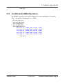
9. Arithmetic Logic Unit (alu)
9.3
Special Constants
The ETEC assembler supports the special constants described in this section.
9.3.1
Loading a 24-bit Constant
A 24-bit number can be loaded only into the diob, P, sr or A registers, as follows.
alu diob = 0x123456.
In this situation no additional sub-instructions are supported, except the return. Note that a
constant and a return are used together with the dispatch jump to generate a special highlevel construct, as described in section 15.6,Constant .
Fie ld: T2D
9.3.2
The "One" Constant
A constant of one can be added to a register in formats that support the CIN field, as
follows.
alu sr = diob + sr + 1.
A constant of one also can be used in a subtraction operation, as follows. When used as a
subtraction then both the CIN and the BINV fields are asserted.
alu sr = diob - sr – 1.
Because subtraction and carry have their own fields, these operations are available with
most of the operations specified by the SHF and ALUOP fields, as follows.
// Subtract, carry, and shift right
alu diob =>> a - sr – 1.
Fie ld: CIN
9.3.3
The ‘max’ Constant
A ‘max’ constant is important in the ETPU as it represents the maximum time in the future
that the 24-bit ETPU can handle. Max is equal to 0x800000, and short hand ‘max’
construct and is identical and interchangeable with a value of 0x800000, as follows.
alu sr = diob + max.
alu sr = diob + 0x800000.
page 50, Assembler Reference Manual
(C) 2007-2015
Freescale Syntax
9. Arithmetic Logic Unit (alu)
Larger constants are supported, but these represent past events. Generation of this special
constant requires the CIN, BINV, and T4BBS fields. As such it is supported only when
added and only as the B-bus source.
Fie ld: CIN, BINV, T4BBS
9.4
Addition And Subtraction
The ETEC assembler supports the addition and subtraction operations described in this
section.
9.4.1
Two-Register Addition
Two registers can be added together as follows. An increment is supported using the CIN
field.
alu a = diob + sr.
alu a = diob + sr + 1.
Fie ld: SHF, ALUO P, CIN
9.4.2
Subtraction of One Register by another Register
One register can be subtracted from another, as follows. Note that subtraction requires
the BINV and the CIN fields, so only formats that support those fields support subtraction.
alu a = diob - sr.
alu a = diob – sr - 1.
Fie ld: BINV, CIN
9.4.3
Addition by a Constant
A register can be added to a constant, as follows.
alu sr = diob + 0x1235.
Excluding some special constants defined elsewhere these constants are only supported by
the ‘format A’ opcodes.
Fie ld: IMM
Freescale Syntax
(C) 2007-2015
Assembler Reference Manual, page 51
9. Arithmetic Logic Unit (alu)
9.5
Addition and Subtraction with the Carry Flag
Two registers can be added together or subtracted from one another along with the carry
flag, as follows.
alu a = diob + sr + C.
alu a = diob - sr - C.
Note 1: The CIN is ignored (except when generating the special ‘max’ constant) and the
BINV field generates the subtraction.
Note 2: When the ‘max’ is being generated from the BINV and CIN fields both being
asserted, then the behavior is that of a subtraction, as follows:
alu a = diob - max + C.
Fie ld: ALUO P, value 0b11000
9.6
Single-Bit Shift and Rotate
The ETEC assembler supports the single-bit shift and rotate operations described in this
section.
9.6.1
Two-Register Addition with Shift or Rotate
One register can be added to another register with a post-shift left, shift right, or rotate
right. The shift or rotate is always by a single-bit position, as follows
alu a =<< diob + sr.
alu a =>> diob + sr.
alu a =R> diob + sr.
// Shift left
// Shift right
// Rotate right
Fie ld: SHF and ALUO P, value s 0b10101, 0b10110, and 0b10111
9.6.2
Two-Register Subtraction with Shift or Rotate
Subtraction with shift or rotate by a single-bit position is also supported, similar to above.
alu a =<< diob - sr.
alu a =>> diob - sr.
alu a =R> diob - sr.
// Shift left
// Shift right
// Rotate right
Fie ld: SHF and ALUO P, value s 0b10101, 0b10110, and 0b10111
page 52, Assembler Reference Manual
(C) 2007-2015
Freescale Syntax
9. Arithmetic Logic Unit (alu)
9.6.3
Addition to a Constant with Shift or Rotate
Addition with an eight-bit constant, followed by a shift left, shift right, or rotate right are
supported, as follows. Note that only a shift and rotate of one are supported.
alu a =>> diob + 0x55. // Shift right
alu a =<< diob + 0x55. // Shift left
alu a =R> diob + 0x55. // Rotate right
Fie ld: SHF and ALUO PI, value s 0b10101, 0b10110, and 0b10111
9.7
Multiple-Bit Shift and Rotate
The ETEC assembler supports the multiple-bit shift and rotate operations described in this
section.
9.7.1
Multiple-Bit Shift and Rotate by a Register
A register can be used to specify the number of bit positions to shift left, shift right, and
rotate right a second register. Curiously, the amount of bit-positions is NOT equal to the
value of the first register. Rather the number shifted is per the somewhat bizarre
relationship as follows. Note that only shifts of 2, 4, 8, or 16 are supported.
B-bus
Shift A-bus by this many bits
0
2
1
4
2
8
3
16
The following shows the syntax for the shift left, shift right, and rotate right.
alu a = diob <<
alu a = diob >>
alu a = diob >>R
Freescale Syntax
(2^^(sr+1)).
(2^^(sr+1)).
(2^^(sr+1)).
(C) 2007-2015
// Shift left
// Shift right
// Rotate right
Assembler Reference Manual, page 53
9. Arithmetic Logic Unit (alu)
The B-Bus can be inverted prior to the using the tilde character, ~, as follows.
alu a = diob <<
(2^^(~sr+1)).
Note: The CIN field is ignored in these operations.
9.7.2
Multiple-Bit Shift and Rotate by a Constant
A register can be shifted left, shifted right, or rotated right as follows.
alu a =<<2 diob.
alu a =<<4 diob.
alu a =R>2 diob.
Note that the number of bit positions shifted or rotated is 2, 4, 8, and 16.
9.8
Bitwise operations; 'OR', 'AND', and 'XOR'
The ETEC assembler supports the bitwise 'OR', 'AND', and 'XOR' operations described in
this section.
9.8.1
Register-Register ‘Or’, ‘And’ and ‘Exclusive Or'
Bitwise OR, AND, and XOR operations of two registers are supported as follows.
alu a = diob | sr.
alu a = diob & sr.
alu a = diob ^ sr.
// OR
// AND
// XOR
The B-Bus can be inverted prior to the using the tilde character, ~, as follows.
alu a = diob | ~sr.
Note: The CIN field is ignored in these operations except when generating the special
‘max’ constant.
Fie ld: ALUO P, bit value s 0b1000, 0b10001, and 0b10010
page 54, Assembler Reference Manual
(C) 2007-2015
Freescale Syntax
9. Arithmetic Logic Unit (alu)
9.8.2
Bitwise Or, And, and Exclusive Or Using a Constant
Bitwise ‘OR’, ‘XOR’ and ‘AND’ operation using a constant are supported as follows.
alu
alu
alu
alu
alu
alu
alu
alu
alu
alu
alu
alu
a
a
a
a
a
a
a
a
a
a
a
a
=
=
=
=
=
=
=
=
=
=
=
=
diob
diob
diob
diob
diob
diob
diob
diob
diob
diob
diob
diob
low| 0x55, ccs.
low& 0x55, ccs.
low&0 0x55, ccs.
low^ 0x55, ccs.
mid| 0x55, ccs.
mid& 0x55, ccs.
mid&0 0x55, ccs.
mid^ 0x55, ccs.
high| 0x55, ccs.
high& 0x55, ccs.
high&0 0x55, ccs.
high^ 0x55, ccs.
//
//
//
//
//
//
//
//
//
//
//
//
a
a
a
a
a
a
a
a
a
a
a
a
=
=
=
=
=
=
=
=
=
=
=
=
diob
diob
diob
diob
diob
diob
diob
diob
diob
diob
diob
diob
|
&
&
^
|
&
&
^
|
&
&
^
0x000055
0xFFFF55
0x000055
0x000055
0x005500
0xFF55FF
0x005500
0x005500
0x550000
0x55FFFF
0x550000
0x550000
Note that the bitwise OR constant must be in one of the following ranges:
(0x0 .. 0xFF)
This limitation is due to the fact that the immediate data value is limited to eight bits. This
eight-bit value can be applied on any byte boundary.
In addition, for the bitwise AND operation only, the following constant range is also
allowed.
(0x0 .. 0xFF)
Fie ld: ALUO PI, bit value s 0b1000 through 0b10011.
9.9
Bit Set and Bit Clear
The ETEC assembler supports the bit set and bit clear operations described in this section.
9.9.1
Single-Bit Set and Bit Clear, by Register
A register is used to determine which bit to set or clear in a second register, as follows.
alu a = setb diob[sr].
alu a = clrb diob[sr].
Note that only the least significant five bits of the sr register are used to determine which
bit to set or clear. A value of greater than 32 may still perform a bit set or bit clear, as long
Freescale Syntax
(C) 2007-2015
Assembler Reference Manual, page 55
9. Arithmetic Logic Unit (alu)
as the least significant five bits reference a valid bit position. The valid bit position range is
0..23 for a 24-bit register.
The B-Bus can be inverted prior to the operation using the tilde character, ~, as follows.
// Single-bit clear, B-Bus Invert
alu a = clrb diob[~sr].
Note: The CIN field is ignored in these operations except when generating the special
‘max’ constant.
Fie ld: ALUO P, bit value s 0b11101, and 0b11110
9.10
Single-Bit Exchange with the Carry Flag
Enter topic text here.
9.10.1 Exchange the “c” Flag with a Bit, Register Specified
A register-specified bit can be exchanged with the “c” flag, as follows.
alu a = excb diob[sr].
Only the least significant five bits are used in calculation of the bit position, such that values
greater than 31 are truncated to be in the range 0..31.
The B-Bus can be inverted prior to the operation using the tilde character, ~, as follows.
alu a = excb diob[~sr].
Note: The CIN field is ignored in this operation except when generating the special ‘max’
constant.
Fie ld:: ALUO P, value 0b11100
9.10.2 Exchange the C Flag with a Bit, Constant Specified
The “c” flag and a bit can be exchanged as follows.
alu a = excb diob[14].
The result of this operation is to exchange the “c” flag with a bit in the A-bus source
register. Note that the A-bus source register is not modified; rather the result is placed in
the A-bus destination. Any bit position can be specified.
page 56, Assembler Reference Manual
(C) 2007-2015
Freescale Syntax
9. Arithmetic Logic Unit (alu)
Fie ld: ALUO PI, value s 0b11001, 0b11010, and 0b11011.
9.11
Absolute Value
The absolute value of the result of an addition operation can be calculated, as follows
alu a = abs(diob).
Note that only the A-bus source is used to calculate the absolute value as the B-bus source
is ignored. The BINV and CIN fields are also ignored.
Fie ld: ALUO P, value s 0b10011
9.12
B-Bus Inversion and Carry-In
alu bitwise operations generally ignore the carry-in bit (CIN field) except when generating
the special ‘max’ constant. The operations that ignore the CIN field are OR, XOR, AND,
ABS, ADC/SBC, SHL, SHR, ROR, EXCH, SETB, and CLRB. For these operations the
B-Bus can generally still be inverted using the special tilde character, ~, as follows:
alu a = diob | ~sr.
alu non-bitwise operations generally support the carry-in bit (CIN field) and in such cases
the syntax is that of subtracting the B-Bus. The asserted state of the BINV field and the
CIN field is a zero. The syntax used to generate all four possible combinations of BINV
and CIN is as follows.
alu
alu
alu
alu
9.13
a
a
a
a
=
=
=
=
diob
diob
diob
diob
+
+
–
sr.
sr + 1.
sr – 1.
sr.
//
//
//
//
BINV=1,
BINV=1,
BINV=0,
BINV=0,
CIN=1
CIN=0
CIN=1
CIN=0
Saving the Flags
The alu has overflow (v), negative (n), carry (c), and zero (z) flags. These flags default to
not saved. It is possible to override the default ,such that the flags are saved, as follows.
alu a = diob – sr, ccs.
The default flag discarding behavior can be actively enforced, as follows.
alu a = diob – sr, ccd.
Fie lds CCV, CCSV.
Freescale Syntax
(C) 2007-2015
Assembler Reference Manual, page 57
9. Arithmetic Logic Unit (alu)
9.13.1 Overriding the Default Flag Size
Each alu operation has a "natural size" base on the A-bus source, B-bus source, and
destination registers. The flags are normally calculated based on this natural size, but the
flag calculation size can be overridden to be the specified size, as follows.
alu a = diob + sr, ccs8.
alu a = diob + sr, ccs16.
Fie ld: CCSV
9.14
Shifting the sr register
The sr register can be shifted left by one bit position, as follows.
alu sr =>> 1.
Note that this operation uses the special SRC field and is therefore available in conjunction
together with normal alu operations, as follows.
alu a = diob, shift.
Fie ld: SRC
9.15
Overriding the Default A-Bus Source
The A-bus size is can be overridden by a casting operation similar that that used in C, as
follows..
alu a = diob(8) + sr.
alu a = diob(16) + sr.
// Do 8-bits
// Do 16-bits
Fie ld: ASCE
9.16
A-Bus Source Sign Extension
The A-bus operand can be sign extended such that the register’s most significant bit is
copied through bit 24 as follows.
// 8-bit sign extension
alu p = p31_24 + diob, sext.
// 16-bit sign extension
alu p = p31_16 + diob, sext.
page 58, Assembler Reference Manual
(C) 2007-2015
Freescale Syntax
9. Arithmetic Logic Unit (alu)
Fie ld: SEXT
9.17
Conditional ALU/MDU Operations
alu and MDU operations can be made contingent on certain combinations of certain alu
flags. The supported combinations are as follows.
*
*
*
*
*
alu's carry flag is true
alu’s carry flag is false
alu’s zero flag is true
alu’s zero flag is false
alu’s negative flag is true
alu if C == 1
alu if C == 0
alu if Z == 1
alu if Z == 0
alu if N == 1
then
then
then
then
then
diob
diob
diob
diob
diob
=
=
=
=
=
diob
diob
diob
diob
diob
+
+
+
+
+
0x37.
0x37.
0x37.
0x37.
0x37.
Fie ld: ASCE
Freescale Syntax
(C) 2007-2015
Assembler Reference Manual, page 59
page 60, Assembler Reference Manual
10. The Multiply Divide Unit
10
The Multiply Divide Unit
The multiply divide unit (MDU) supports multiply and divide operations. Both register-byregister and register-by-constant-operations are supported. The MDU is distinct from the
alu for the reasons listed below.
*
*
*
*
10.1
Results are always stored in the MAC register.
The MDU has its own set of flags; MZ, MC, MN, MV.
The MDU flags are always saved and are not affected by SampleFlags.
Operations require multiple micro-cycles.
MDU Multiply
The MDU supports multiply by a constant and register-by-register multiply. Constants are
always 8-bits whereas in register-by-register multiplies, 8, 16 and 24 bit operations are
supported. All multiplies can be either signed or unsigned.
Multiply operations take multiple cycles to complete. The number of cycles depends on the
size of the operation. The reader is referred to the Freescale literature for the specifics.
10.1.1 Multiply by a Constant
Both an unsigned and signed multiplication by an eight-bit constant is supported, as follows.
mdu diob multu 0x37.
mdu sr mults 0xE7.
Freescale Syntax
(C) 2007-2015
Assembler Reference Manual, page 61
10. The Multiply Divide Unit
Note that the register named MAC is a 48-bit register that consists of MACH (upper 24bits) and MACL (lower 24-bits).
A couple special notes apply to the signed multiply only. All operands are sign extended to
24 bits prior to the operation. The result therefore fills the entire 48-bit MAC register.
Also, a 16-bit operand extends the 15th bit to fill the entire 24-bits. Likewise, an 8-bit
operand is sign extended to fill the entire 24-bit operand, per the following example.
// Bit 15 is sign-extended
mdu p7_0 mults 0x37.
// Bit 15 is sign-extended
mdu p7_0 mults 0x37.
10.1.2 MDU Register By Register Multiply
Signed and unsigned 8-, 16-, and 24-bit register-by-register multiplies are supported, as
follows. Note that unless the A-bus source size is overridden, the entire 24-bits of the Abus source are used. In the following examples, therefore, all 24 bits of the diob register
are used.
mdu
mdu
mdu
mdu
mdu
mdu
10.2
diob
diob
diob
diob
diob
diob
multu
mults
multu
mults
multu
mults
sr(8).
sr(8).
sr(16).
sr(16).
sr.
sr.
MDU Multiply and Accumulate
The ‘multiply and accumulate’ operation performs both a multiply and an addition in the
same operation. This supports a running total of a series of multiply operations.
The MAC register is always the source for the addition as well as the destination. The
multiply source is two general-purpose registers. Similar to the multiply operation, both
signed and unsigned 8-, 16-, and 24 bit operations are supported, as follows.
mdu diob macs sr.
mdu diob macu sr.
These operations require multiple cycles to complete. Some add/multiply parallelism is
allowed. For these specifics the reader is referred to the Freescale literature.
page 62, Assembler Reference Manual
(C) 2007-2015
Freescale Syntax
10. The Multiply Divide Unit
10.3
Fractional Multiply
A fractional multiply is supported for 8-bit and 16-bit signed and unsigned multiplies, as
follows.
mdu
mdu
mdu
mdu
diob
diob
diob
diob
fmults
fmults
fmultu
fmultu
sr(8).
sr(16).
sr(8).
sr(16).
Signed and unsigned fractional ‘multiply by a constant’ are also supported.
// Signed fraction multiply
mdu diob fmults 37.
// Unsigned fraction multiply
mdu diob fmultu 52.
10.4
Additional MDU B-Bus Options
In some MDU operations a combination of the negative B-Bus and a B-Bus pre-increment
can be used. But not all MDU operations support all combinations of negative B-Bus and
B-Bus pre-increment. The capabilities and limitations depend on whether the MDU
operation is considered to be signed or unsigned.
10.4.1 MDU Unsigned B-Bus operations
In unsigned B-Bus operation the B-Bus can have a pre-increment but the negative
(inverted) B-Bus is not supported. This is shown below. Surprisingly, the fractional
operations are all considered to be unsigned as far as this capability/limitation goes.
mdu
mdu
mdu
mdu
mdu
mdu
mdu
mdu
mdu
mdu
mdu
Freescale Syntax
diob
diob
diob
diob
diob
diob
diob
diob
diob
diob
diob
multu sr(8).
multu sr(16).
multu sr.
fmultu sr(8).
fmultu sr(16).
fmults sr(8).
fmults sr(16).
macs sr.
div sr(8).
div sr(16).
div sr.
(C) 2007-2015
Assembler Reference Manual, page 63
10. The Multiply Divide Unit
10.4.2 MDU Signed B-Bus operations
In signed B-Bus operation the B-Bus can be negative but a pre-increment is not supported.
This is shown below. Surprisingly, the fractional operations are all considered to be
unsigned as far as this limitation goes, so this applies only signed 8, 16, and 24-bit multiplies
and the 24-bit multiply and accumulate.
mdu
mdu
mdu
mdu
diob
diob
diob
diob
mults -sr(8).
mults -sr(16).
mults -sr.
macs -sr.
Note that the pre-increment on a positive (non-inverted) B-Bus and the pre-decrement on
a negative (inverted minus one) B-Bus are not supported.
10.5
MDU Divide
MDU divides by both constants and register-by-register are supported. Unlike the MDU
multiply, only unsigned operations are supported. Divide by zero results in a global
exception.
Divide operations take multiple cycles to complete. The number of cycles depends on the
size of the operation. The reader is referred to the Freescale literature for the specifics.
10.5.1 MDU Divide by a Constant
The MDU supports division by an 8-bit unsigned constant, as follows.
mdu diob div 0xE7.
10.5.2 MDU Register by Register Divide
Similar to the MDU multiply, 8, 16, and 24 bit operations are supported. But only unsigned
operations are supported.
mdu diob div sr(8).
mdu diob div sr(16).
mdu diob div sr.
page 64, Assembler Reference Manual
(C) 2007-2015
Freescale Syntax
10. The Multiply Divide Unit
10.6
Mac Busy Wait Loop
Following a MAC operation the results are not available until several cycles later. A macbusy-wait loop can be constructed as follows that allows the mac operation to complete
prior to the mac results being read.
MyMacBusyWaitLoop:
seq if mbsy==true then goto MyMacBusyWaitLoop, flush.
alu p = macl;
ram p ->Result0.
<...>
Note that to support Worst Case Thread Length (WCTL) analyses and for the assembly to
be optimize-able, the 'if' sub-instruction must have 'flush' set, the loop must branch on 'true'
and the loop destination label must be immediately above the 'if' instruction.
Freescale Syntax
(C) 2007-2015
Assembler Reference Manual, page 65
page 66, Assembler Reference Manual
11. Channel Hardware Sub-Instructions
11
Channel Hardware
Sub-Instructions
Channel sub-instructions provide the capability to modify channel hardware. Channel
hardware is differentiated from other aspects of the ETPU in that there are channel
hardware resources that belong to each of the 32 ETPU channels. For example, there are
32 Match Recognition Latch A's (MRLA), one for each channel. There is also a channel
hardware sub-instruction for clearing this latch.
Channel hardware sub-instructions generally act on the channel hardware specified by the
channel register. In most cases the channel register can be modified so that the channel
resources from a specific channel number can be modified. But this is not always the
case. Some resources are "stuck" to the original channel number so that even if the
channel register is changed, the channel resources from the original channel number are
always modified. In other cases a channel register modification takes several subinstructions to take affect so that channel sub-instructions one or two sub-instructions
following a channel register change still act on the original channel, and only after these
instructions act on the new channel. The reader is referred to the Freescale literature for
the specifics.
Freescale Syntax
(C) 2007-2015
Assembler Reference Manual, page 67
11. Channel Hardware Sub-Instructions
11.1
Channel Flags
Each channel has two channel flags, ChannelFlag1 and ChannelFlag0. Unlike the TPU,
these channel flags cannot be directly tested using a sequencer sub-instruction. Instead,
they are used as part of the thread table to direct a thread to start at a particular section of
code.
Channel flags can directly cleared and set, as follows.
chan
chan
chan
chan
set flag0.
clear flag0.
set flag1.
clear flag1.
Both channel flags can also be set to the value of adjacent bits within the P register, as
follows. Note that the only valid P register pairs are [31..30], [29..28], and [27..26]; and
ChannelFlag1 must always be set to the higher numbered bit.
chan flag10 = p2524.
chan flag10 = p2726.
chan flag10 = p2928.
Fie ld: FLC
11.2
Time Base and Comparator
A match can be programmed to occur on either an "equal" or "greater than or equal to"
condition.
A match event can be programmed to be based on either the TCR1 or the TCR2 counter
value.
A capture event occurs in two situations: on a match event and on an input transition event.
On a capture event, the capture register can be programmed to be loaded with either the
TCR1 or TCR2 counter value.
In addition, since the ETPU is double pumped, it has two separate action units for each
channel. These three settings for each of the action units are programmed using the
following instruction, where X is specifies the action unit, Y specifies which counter to
match, and Z specifies the counter to capture.
chan tbsX = matchY_capZ_ge.
For example, to program action unit B to match events based on the TCR1 counter base on
the "greater than or equal to" test and to capture TCR2, the following syntax is used.
page 68, Assembler Reference Manual
(C) 2007-2015
Freescale Syntax
11. Channel Hardware Sub-Instructions
chan tbsa = match1_cap2_ge.
To set the same set of conditions as above, but to match on "equals" condition instead of
"greater or equal," use the following.
chan tbsb = match1_cap2_eq.
Fie ld: TBSA, TBSB
11.3
Output Buffer
Each channel has separate input and output nodes. But in some cases the input and output
nodes can be tied together forming an I/O pin on the physical device. In such case the
ETPU channel can be used as an output by enabling the output buffer, or as an input by
disabling the output buffer. This is done as follows.
chan tbsa = enable_output_buffer.
chan tbsa = disable_output_buffer.
Note that this capability uses the TBSA field, and this sub-instruction is therefore not
available in an instruction that also sets action unit A.
Fie ld: TBSA
11.4
Immediate Output Pin State Control
Although the ETPU is best used by programming events to occur in the future using the
Output Pin Action Command fields (OPACA and OPACB), it is also possible to force an
immediate pin state, as shown below. The pin can be forced high, low, or to a value
specified in the OPACA or OPACB field.
chan
chan
chan
chan
pin
pin
pin
pin
=
=
=
=
high.
low.
opaca.
opacb.
Fie ld: PSC, PSCS
11.5
Input Pin Transition Detection
An input pin transition can be detected on each of the action units. Detectable transitions
are a rising edge (low-to-high), a falling edge (high-to-low), or a toggle (high to low and
low to high). Detection can also be disabled by setting it to off.
Freescale Syntax
(C) 2007-2015
Assembler Reference Manual, page 69
11. Channel Hardware Sub-Instructions
chan
chan
chan
chan
ipaca
ipaca
ipaca
ipaca
=
=
=
=
low_high.
high_low.
any_trans.
no_detect.
Since the ETPU is "double pumped," input pin detection can be programmed into both
action units. The second action unit is programmed as follows.
chan
chan
chan
chan
ipacb
ipacb
ipacb
ipacb
=
=
=
=
low_high.
high_low.
any_trans.
no_detect.
A window can be created so that an input transition is detected only if it occurs within a
particular time-frame. This is done as follows.
chan
chan
chan
chan
ipacb
ipacb
ipaca
ipaca
=
=
=
=
detect_input_0_on_match.
detect_input_1_on_match.
detect_input_0_on_match.
detect_input_1_on_match.
Note that transition detection is more complicated than would be implied by just this field.
Additional conditions affect transition detection such as the ability to block detection on
action unit B until action unit A has detected a transition. Careful attention must be paid to
the channel mode as configured by the PDCM field.
Fie ld: IPACA, IPACB
11.6
Output pin Action
The output pin can be programmed to go to a particular state on a match in action unit A as
follows.
chan
chan
chan
chan
opaca
opaca
opaca
opaca
=
=
=
=
high.
low.
toggle.
no_change.
Action unit B supports the same capability, as follows.
chan
chan
chan
chan
opacb
opacb
opacb
opacb
=
=
=
=
high.
low.
toggle.
no_change.
In addition, an input pin transition can also generate a similar output pin action.
chan opaca = transition_low.
page 70, Assembler Reference Manual
(C) 2007-2015
Freescale Syntax
11. Channel Hardware Sub-Instructions
chan opaca = transition_high.
chan opaca = transition_toggle.
This is also supported by both action units, as follows.
chan opacb = transition_low.
chan opacb = transition_high.
chan opacb = transition_toggle.
Note that this command does not immediately modify the output pin state. Instead, it
prepares a response to some (typically) future event, and therefore it should use the
FutureOutputPin naming convention. Use of this sub-instruction, though conceptually more
difficult to understand than simply setting or clearing the current output pin via the PSC
field, is what gives the ETPU the capability for such incredibly small latencies. Use of this
sub-instruction therefore unleashes the full power of the ETPU.
The output pin action functionality is not as simple as might be implied by this description.
The exact functionality is influenced by the PDCM field.
Fie ld: O PACA, O PACB
11.7
Writing the Match Registers
Each channel's match registers can be written. When writing a match register, the
corresponding Match Recognition Latch Enable (MRLE) is concurrently set. A set MRLE
is one of the things required to enable a match. Note that the ERT register is the only
allowed source when writing a corresponding match register.
chan write_erta.
chan write_ertb.
Fie ld: ERWA, ERWB
11.8
Reading the Match Registers
The matchA and matchB registers can both be read into the corresponding erta and ERTB
registers with the following sub-instruction. Note that both registers MUST be written
together, and the only valid destination are their respective ERT registers.
A twist of fate put this capability in the T4ABS field thereby preventing use of this subinstruction with an alu instruction that would require the T4ABS field. What curious webs
we weave.
alu read_mer12.
Freescale Syntax
(C) 2007-2015
Assembler Reference Manual, page 71
11. Channel Hardware Sub-Instructions
Fie ld: T4ABS
11.9
Reading the Capture Registers
Although there is no direct way of reading the capture registers, there is an indirect way.
This is accomplished by writing the channel register as shown below.
alu chan = chan.
// The ErtA register now contains the CaptureA value
// The ErtB register now contains the CaptureB value
Note that there are numerous other consequences of writing the channel register such as
the TDL and other flags get re-sampled. Refer to the eTPU documentation for a complete
list.
11.10 Clearing the Match Recognition Latches
The match recognition latches become set when a match event occurs in their respective
action units. Such a match sets the match recognition latch. A set match recognition latch
does a number of things that are somewhat determined by the PDCM field. A set match
recognition latch generally causes a capture and generally results in a new ETPU thread.
The match recognition latches for each of the action units can be cleared, individually or in
tandem, as follows.
chan clr_mrla.
chan clr_mrlb.
Fie ld: MRLA, MRLB
11.11 Clearing the Transition Detection Latches.
The transition detection latch gets set when the requisite set of conditions causes a
transition to be detected. Although each action unit has its own transition detection latch,
only a single sub-instruction is provided for clearing both latches, as follows.
chan clr_tdl.
Note that a significant limitation in eTPU1 is that only support ordered transition detection
is supported. The inability to individually negate each TDL latch is one aspect of that
eTPU1 limitation.
page 72, Assembler Reference Manual
(C) 2007-2015
Freescale Syntax
11. Channel Hardware Sub-Instructions
In eTPU2 only, the TDLA and TDLB latches can be cleared individually as follows.
chan clr_tdla.
chan clr_tdlb.
Fie ld: TDL
11.12 Clearing Link Service Requests
One channel can cause servicing of another channel by writing a channel number to the
link register. The channel number specifies the channel that will get serviced. That linked
channel’s Link Service Latch gets set, thereby causing the linked channel to get serviced.
Upon servicing, the linked channel will generally clear this request. Clearing prevents the
linked channel from immediately becoming serviced again following the end of the thread.
Clear the Link Service Request using the following sub-instruction.
chan clr_lsr.
Fie ld: LSR
11.13 Disabling Matches
In order for a match event to occur, matches must be enabled by setting the Match
Recognition Latch Enable (MRLE). Normally this is set (enabled) automatically when the
match register is written. A single sub-instruction clears both latches, as follows. Note
that this disables matches, thereby undoing what was automatically done when the match
register was written.
chan neg_mrle.
Note that in the normal course of events the match enable latches get cleared when a
match occurs. This command is therefore somewhat redundant and is generally not used
in a typical ETPU flow of events.
Fie ld: MRLE
11.13.1 Individual Match Disable on eTPU2
eTPU2 supports individual clearing of each action unit’s Match Recognition Latch Enable
using the following commands.
chan clr_mrlea.
Freescale Syntax
(C) 2007-2015
Assembler Reference Manual, page 73
11. Channel Hardware Sub-Instructions
chan clr_mrleb.
Fie ld: MRLE
11.13.2 Individual Match Disable Limitation
Due to an eTPU2 (silicon) design significant oversight, when individually clearing a
MatchEnableLatch, semaphores must either be locked or freed. This is because the subinstruction used to individually clear semaphores is only found in instruction formats ‘D4’
and ‘D8’ and both of these formats are used to lock and free semaphores and there is no
way to quisce the lock/free semaphore mechanism in these two formats.
ASH WARE recommends the following approach to semaphores when individually
clearing a Match Recognition Latch.
* If all semaphores are free in the section of code in which an individual
MatchRecognitionLatchEnable is cleared, then clear semaphores. Clearing semaphores
in this situation is effectively a NOP.
* If a semaphore is locked in the section of code, then lock the already-locked semaphore
again. Since the semaphore is already locked, locking it again is effectively a NOP.
* If the semaphore state is indeterminate in this section of code (such that it might be either
set or clear due to conditional logic) then there is no good strategy and your code must
be re-designed to make the semaphore state determinate.
* Clear both action units’ MatchRecognitionLatchEnable in the same sub-instruction. The
sub instruction that clears them together is found in instruction formats in which
semaphore operation is quisced.
11.14 Enabling Matches
Matches are enabled by writing the match register. See the "Writing the Match Registers"
section for a description.
11.15 Disabling Match and Transition Service Requests
Servicing of match and transition events can be disabled using the sub-instruction shown
below.
chan mtd = enable_mtsr.
chan mtd = disable_mtsr.
This command does NOT prevent the match or transition detection event. Instead, it only
page 74, Assembler Reference Manual
(C) 2007-2015
Freescale Syntax
11. Channel Hardware Sub-Instructions
prevents the micro-sequencer from entering a thread as a result of these events. The
actual events are not prevented from occurring.
Remember, servicing is normally initiated by any one of the following events:
*
*
*
*
A
A
A
A
match event
transition event
link from another channel
host service request from the host CPU
The EnableMatchTransitionServicing command prevents servicing caused only by the first
two from the above list. A link or a host service request is not blocked from generating a
service event.
In eTPU2 only, the following construct supports a mode in which the CaptureA register is
continuously updated on every incoming transition.
chan mtd = disable_mtsr_enable_cc.
Fie ld: MTD
11.16 Setting the Channel Modes
The double-pumped nature of each ETPU channel necessitates the ability to configure the
ETPU in more detail than provided by the Time Base Selection (TBS), Input Pin Action
(IPAC), or Output Pin Action (OPAC) fields. For example, two edges can be generated,
one by each action unit. This allows generation of pulse width down to a single TCR
counter tick, something the legacy TPU was incapable of doing. But servicing following
both edges would be wasteful in that twice as many service routines would be generated
than are actually needed. The Channel Mode can be set up so that only the second edge
actually results in a service routine.
The details of each of the following sub-instructions are too complicated to be described by
this descriptive assembly syntax, or by this document. The user is therefore referred to the
Freescale literature for an exact explanation of how each of these works.
chan
chan
chan
chan
chan
chan
chan
Freescale Syntax
pdcm
pdcm
pdcm
pdcm
pdcm
pdcm
pdcm
=
=
=
=
=
=
=
em_b_st.
em_b_dt.
em_nb_st.
em_nb_dt.
m2_st.
m2_dt.
bm_st.
(C) 2007-2015
Assembler Reference Manual, page 75
11. Channel Hardware Sub-Instructions
chan
chan
chan
chan
chan
chan
chan
pdcm
pdcm
pdcm
pdcm
pdcm
pdcm
pdcm
=
=
=
=
=
=
=
bm_dt.
m2_o_st.
m2_o_dt.
udcm.
sm_st.
sm_dt.
sm_st_e.
// eTPU2 Only!
11.16.1 eTPU2’s User-Defined Channel Mode
In eTPU2 only, the underlying channel-mode settings can be individually programmed
thereby providing significantly improved granularity to the operation of the channel
hardware. This is done first by writing the User-Defined Channel Mode value into the
ertA register, then transferring the ertA register contents into the User Define Channel
Mode register (UDCM) then setting the Pre-Defined Channel Mode (PDCM) to ‘UDCM’
as follows.
// Desired UDCM value into ertA
alu ertA = 0x1234.
chan udcm = ertA.
chan pdcm = udcm.
Fie ld: PDCM, UDCM
11.17 Interrupts
Each channel can interrupt the host to initiate a data transfer handler or to initiate a generic
"channel" handler. Because each channel has its own interrupts, the host can have a
separate handlers for each channels' interrupt service routines.
chan cir.
chan dtr.
A single global exception also is available. Unlike the channel interrupt, there is only a
single global exception, which is shared by all channels. Regardless of the value of the
channel register, the same global exception is generated.
chan ge.
Note that the channel interrupt and the data transfer interrupt always operation on the
channel that began the thread. For example, if a thread responds to an event on channel 4,
then the user channels the active channel to channel 21 (by writing a 21 to the ‘chan’
register) and asserts a data interrupt, the interrupt still occurs on channel 4.
page 76, Assembler Reference Manual
(C) 2007-2015
Freescale Syntax
11. Channel Hardware Sub-Instructions
Fie ld: CIRC
11.17.1 eTPU2’s Current Channel Interrupt
In eTPU2 the current channel’s interrupt can be set as follows.
chan set CurChan cir.
chan set CurChan dtr.
Note that this overcomes a limitation in the eTPU1 in which an asserted interrupt would
always occur on the originally-serviced channel, even when the ‘chan’ register is changed.
With this new eTPU2 feature, if the channel register is changed an interrupt can be
generated on the new channel, or on the old channel.
Fie ld: CIRC
11.17.2 eTPU2’s Set Both Interrupts
In eTPU2, both channel and data-transfer interrupts can be generated on the same subinstruction as follows. Note that the inteerupts can be generated either on the originallyserviced channel or (assuming the ‘chan’ register has been written) on the new channel.
chan set CurChan BothIntr.
chan set SvcdChan BothIntr.
Fie ld: CIRC
Freescale Syntax
(C) 2007-2015
Assembler Reference Manual, page 77
page 78, Assembler Reference Manual
12. Sequencer Sub Instructions
12
Sequencer Sub Instructions
Enter topic text here.
12.1
Code Labels
A particular code location can be assigned a label, as follows.
SomeCodeLabel:
This label can be referenced by jumps or calls, as follows.
seq if z == 1 then goto ZIsSet.
// <...>
ZIsSet:
Sub instructions: BAF
12.2
Conditional Branch
A condition can be tested, and if the condition is met, then a jump can be taken, as follows.
seq if n == 1 then goto NIsSet.
// <...>
// <...>
NIsSet:
Freescale Syntax
(C) 2007-2015
Assembler Reference Manual, page 79
12. Sequencer Sub Instructions
The branch can also be taken if the condition is not met, as follows.
seq if z == 0 then goto Nope_ZAintSet.
// <...>
// <...>
Nope_ZAintSet:
Sub instructions: BCF
12.3
Conditional Call
A call is identical to a jump, except that the return address register is loaded with a return
address.
seq if z == 1 then call BeamMeUpScotty.
// <...>
// <...>
BeamMeUpScotty:
// <...>
// <...>
seq return.
Note that there is not a formal stack in the ETPU. Use of a stack, while possible, would
require a fair amount of expensive data movement. Think Pittsburg, not Hollywood.
Sub instructions: JC, BCC, BAF, BCF
12.4
Conditionals
The alu's Overflow (v), Negative, (n), Carry (c), and Zero (z) flags can be tested.
seq
seq
seq
seq
if
if
if
if
v
n
C
z
==
==
==
==
1
1
1
1
then
then
then
then
goto
goto
goto
goto
ZIsSet.
NIsSet.
CIsSet.
ZIsSet.
// NOTE CASE!!!
Due to a strange web of lies and half-truths, the ‘C’ flag is case sensitive. This allows the
‘C’ flag (uppercase) to be differentiated from the ‘c’ register (lowercase.)
The alu also supports a test of multiple flags, as follows.
seq if lt then goto YupIsLessThan.
The "less than" conditional examines both the (n) and (v) flags, as follows.
isLessThan = (n && !v) || (!n && v);
page 80, Assembler Reference Manual
(C) 2007-2015
Freescale Syntax
12. Sequencer Sub Instructions
A second multiple flag test is supported.
seq if ls then goto YupItIsLowerEqual.
This flag uses both the “c” and “z” flag, as follows.
isLowSame = C || z;
The MDU supports the same Overflow (mv), Negative, (mn), Carry (mc), and Zero (mz)
flags as the alu, as follows.
seq
seq
seq
seq
if
if
if
if
mv
mn
mc
mz
then
then
then
then
goto
goto
goto
goto
MZIsSet.
MNIsSet.
MCIsSet.
MZIsSet.
During MDU execution of a multiple, multiple-accumulate, or divide, the MAC Busy flag is
set. Upon completion of this operation the MAC busy flag is cleared. This flag can be
tested as follows.
seq if mbsy then goto MacBusyIsSet.
The state of the transition detection latches and match recognitions latches for both action
units can be tested, as follows. Note that the actual channel latches are not being tested.
Rather these are the states of those latches at the time that the thread was entered.
seq
seq
seq
seq
if
if
if
if
tdla
tdlb
mrla
mrlb
then
then
then
then
goto
goto
goto
goto
Tdl_A_IsSet.
Tdl_B_IsSet.
Mrl_A_IsSet.
Mrl_B_IsSet.
Similar to the transition detection latches, the state of the link service request latch is also
sampled at the beginning of the thread state. This is sampled as follows.
seq if lsr then goto LsrIsSet.
Each channel has both an output pin and an input pin. The current states of both of these
can be tested.
seq if psto then goto PstoIsSet.
seq if psti then goto PstiIsSet.
In addition, the input pin state is sampled at the beginning of each state, and re-sampled if
the channel register is written to. This sampled input pin state can also be read, as follows.
seq if pss then goto PssIsSet.
Each channel has two function mode bits that are written by the host CPU. These bits are
sampled at the start of the thread and can be tested by the ETPU as follows.
seq if fm0 then goto Fm0IsSet.
seq if fm1 then goto Fm1IsSet.
Freescale Syntax
(C) 2007-2015
Assembler Reference Manual, page 81
12. Sequencer Sub Instructions
Semaphores provide a mechanism for coherent data access. The semaphore lock flag can
be tested as follows.
seq if smlck then goto SemaphoreLockIsSet.
The alu also supports a test of bits 24 through 31 of the P register, as follows.
seq if p_27 then goto YupBit27IsSet.
Sub instructions: BCC
12.4.1 eTPU2’s Branch on ‘Event’ input pin
In eTPU2, the input pin state is sampled at the first match or transition event that caused
the thread. This ‘Pin Request Sampled State’ (PRSS) can also be branched on, as follows.
seq if prss then goto PrssIsSet.
Sub instructions: BCC
12.4.2 eTPU2’s Branch on Channel Flag
eTPU2 support branching on the channel flags as shown below.
if
if
if
if
12.5
flag0
flag0
flag1
flag1
==
==
==
==
0
1
0
1
then
then
then
then
goto
goto
goto
goto
Flag0IsClr,
Flag0IsSet,
Flag1IsClr,
Flag1IsSet,
no_flush.
no_flush.
no_flush.
no_flush.
Unconditional Goto and Call
A code label can be called or jumped to as follows.
seq goto SomePlaceElse.
seq call SomeFunction.
12.6
Return from subroutine
A return from subroutine uses the following syntax. Note that although this causes the
program counter to be loaded by the return address register (RAR), other registers are not
affected. (This is unlike a normal stack based-processor.)
seq return.
page 82, Assembler Reference Manual
(C) 2007-2015
Freescale Syntax
12. Sequencer Sub Instructions
Sub instructions: RD, RTN
12.7
Flush Pipeline
The jump, call, and return instructions all support a flush pipeline sub-instruction. The very
next instruction following the jump, call, or return instruction is executed prior to the change
in program flow unless flush is active. If the flush is active, then a NOP is inserted.
flushes are therefore wasteful and should be avoided. The default is no_flush;;
The following are uses of the flush instruction:
seq return, flush.
seq if z == 1 then call SomeFunction, flush.
seq if z == 1 then goto SomeLocation, flush.
Note that in a call, the flushed sub-instruction affects the value written to the return
address register. If a flush is asserted then the address of the very next instruction is
written to the return address register. If flush is not asserted then the address of the
instruction following the next instruction is written to the return address register.
The following is wasteful microcode. The order of operations is instruction A, B, C, D.
// InstructionA
// InstructionB
seq if z == 1 then call SomeFunction, flush.
// InstructionD
// <...>
SomeFunction:
// InstructionC
seq return, flush.
The following executes the exact same instructions in the same order as above, but the
wasteful flushes have been removed by re-ordering the instructions.
// InstructionA
seq if z == 1 then call MyFunction.
// InstructionB
// InstructionD
// <...>
MyFunction:
seq return.
// InstructionC
Sub instructions: FLS
Freescale Syntax
(C) 2007-2015
Assembler Reference Manual, page 83
12. Sequencer Sub Instructions
12.8
Dispatch Jump and Dispatch Call
Dispatch jumps and dispatch calls both cause a change of flow. Specifically, the program
counter is increased by the value of the upper byte of the P register. This provides the
following powerful capabilities.
* Extension of state resolution
* Table look-up
ASH WARE provides high-level constructs for both of these capabilities in section 15.6,
Constant , and section 15.5, Jump Table.
Extension of state resolution can be used to effectively extend the entry table. A table of
jump-to-addresses can generated. The upper byte of the P register, which is automatically
loaded at the start of the thread, can be used to contain additional state information. Since
each thread table has 32 addresses, and since the upper byte of the P-register contains an
offset to a table of up to 256 start addresses using this capability, the theoretical number of
unique states is 32*256 or 8092 unique states!
Table look-up is useful for generating a non-linear function or for providing linearity to a
non-linear relationship. For example, the relationship between temperature and voltage of
a thermocouple is non-linear. A linear approximation of this relationship results in an error,
when calculation temperature based on voltage. This error is reduced by looking the
temperature up in a table rather than using a linear approximation. The dispatch call and
dispatch jump can provide this capability.
Dispatch operations dispatch increment the program counter by the value of the upper byte
of the P register, as follows.
ProgramCounter += p_31_24 + flush ? 0 : 4;;
Similar to normal jumps and calls, the return address register is loaded with the return
address on a call, but is not affected by a jump. The wasteful flush option is also available,
and this affects the return address for a call, per the previous equation. The dispatch jump
and dispatch call syntax is as follows.
seq dispatch_call, flush.
seq dispatch_goto, flush.
Although the default is no_flush, it is possible to explicitly specify that the next instruction is
not flushed using the following syntax.
seq dispatch_goto, no_flush.
Sub instructions: RD
page 84, Assembler Reference Manual
(C) 2007-2015
Freescale Syntax
12. Sequencer Sub Instructions
12.9
Ending the Current Thread - END
A thread is terminated with an end sub-instruction. Following the end sub-instruction the
micro-sequencer ceases to execute microcode until a new thread becomes active.
seq end.
Note that a flush sub-instruction has no affect when used in conjunction with an end subinstruction.
Sub instructions: END
Freescale Syntax
(C) 2007-2015
Assembler Reference Manual, page 85
page 86, Assembler Reference Manual
13. Linking to other channels
13
Linking to other channels
Links are similar to host service requests but whereas host service requests are a request
from the host CPU for some action to occur on the eTPU, in a link, the request for action
is generated in the eTPU itself. The eTPU supports a rich set of linking capabilities,
including links from one channel to another channel within that same engine, links to a
specific channel in a specific engine, and cross engine links where a link in the “other”
engine is requested. The syntax for these are as follows.
A link is generated by writing a value to the link register, as follows.
#define LINK_TO_CHAN 5
alu link = LINK_TO_CHAN.
Bits 5:0 specify the channel that is to be linked destination channel. Note that the
destination of the link may be the same channel that generated the link which is known as a
“link to self” and is a common and effective way of breaking a long thread into two shorter
threads.
Bits 7:6 specify that engine being linked to where a zero is the same engine a one is engine
1, a 2 is engine 2, and a 3 is a cross engine link.
Freescale Syntax
(C) 2007-2015
Assembler Reference Manual, page 87
page 88, Assembler Reference Manual
14. Structured Programming
14
Structured Programming
A class structure serves as a container for channel variables and callable member
functions (that can also access the channel variables as follows.
_eTPU_class MyChannelClass
{
int24 X;
int24 Y;
int24 Result;
MemberFunction MyMemberFunc;
};
14.1
Data Types
The following data types are supported.
int24
int32
int8
14.2
// 24-bit native eTPU data type
// 32-bit data type
// 8-bit data type
Data Scopes
Data scope can be global, channel, or engine.
Symbol names are limited to 256 characters.
Freescale Syntax
(C) 2007-2015
Assembler Reference Manual, page 89
14. Structured Programming
14.2.1 Global Variables
The following is an example of declaration and access of global variables.
int24 MyGlobalInt24;
int8 MyGlobalInt8;
int32 MyGlobalInt32;
ram diob
<- MyGlobalInt24.
ram p31_24 <- MyGlobalInt8.
ram p_31_0 <- MyGlobalInt32.
14.2.2 Channel Variables
A class structure serves as a container for variables whose scope is a structure. Code that
accesses these channel variables must be located within a ‘using’ region as follows.
_eTPU_class MyChanVarClass
{
int8 MyChanVar8;
int24 MyChanVar24;
int32 MyChanVar32;
};
using MyChanVarClass
{
ThisThread:
alu diob = 0xBAD.
ram
diob -> MyChanVar24;
seq
end.
}
14.2.3 Engine Variables
Engine variables only exist in eTPU2 and later eTPUs. The –target=etpu2 command line
argument is required in order for engine variables to be allowed.
Engine variables are declared similarly to global variables. The leading keyword ‘engine’ is
used to signify that the variable is placed engine-relative instead of globally. The following
illustrates declaration of 8, 24, and 32-bit engine variables.
engine int32 MyEngine32;
engine int24 MyEngine24;
engine int8 MyEngine8;
page 90, Assembler Reference Manual
(C) 2007-2015
Freescale Syntax
14. Structured Programming
These variables can be read and written similarly to other global variables, with one
exception. Namely, engine variables can be directly set to zero, whereas global variables
can only be loaded with the contents of the ‘p’ or ‘diob’ register.
ram
ram
ram
ram
ram
14.3
p31_0
p23_0
diob
p31_24
#0
->
<<->
->
MyEngine32.
MyEngine24.
MyEngine24.
MyEngine8.
MyEngine24.
//
//
//
//
//
32-bit write
24-bit read
24-bit read (diob)
8-bit write
Clr an engine variable
Referencing an Address
It is possible to reference the address of a global variable, channel variable, engine variable
or a code label as follows.
MyRefCodeLabel:
alu diob = MyEngine24.
alu sr = MyGlobal8.
alu a = MyChanVar32.
alu diob = MyRefCodeLabel.
See the next section of a discussion on why code label addresses load the word address
and not the byte address.
14.3.1 Referencing Code Address Note
When referencing a code address the WORD address is taken not the byte address. This
is because the Return Address register (RAR) operates on the WORD address and not
the byte address. By taking the byte address, the address can immediately be used (as a
pseudo indirect call) using the ‘seq return’ sub instruction, as seen in the following
example.
Freescale Syntax
(C) 2007-2015
Assembler Reference Manual, page 91
14. Structured Programming
In the example shown above the referenced code address of MyCodeLabel is 0x964. But
a 0x259 is loaded into the ReturnAddr register. Why? Because 0x964/4=0x259. The byte
address is divided by four to generate the word address.
14.4
Class Member Functions
Class member functions are functions that are both callable and can access the channel
variables. If optimization or analyses is enabled in the linker, class member functions must
be surrounded by the special #pragma mimic_c_func_start and #pragma
mimic_c_func_end.
_eTPU_class MyChanMemClass
{
int24 X;
int24 Y;
int24 Result;
MemberFunction MyMemberFunc;
};
using MyChanMemClass
{
MyThread:
seq call MyMemberFunc, flush.
seq
end.
#pragma mimic_c_func_start
MyMemberFunc:
page 92, Assembler Reference Manual
(C) 2007-2015
Freescale Syntax
14. Structured Programming
alu diob = 0xBAD.
ram diob -> Result;
seq return, flush.
#pragma mimic_c_func_end
}
Note that if optimization or analyses is enabled in the linker then there are a number of
limitations to any called function (including class member functions.) These limitations are
listed below
*
*
*
*
*
*
14.5
The only allowed program-flow exit is via a ‘return’, ‘end’, or another call
The only allowed program-flow entry point is the very first opcode
The function must have at least one opcode
The function may ONLY be accessed via a call (never a goto)
Indirect calls via writing the return address register are NOT allowed
The return address register may only be written in save/restore operations within the
prologue/epilogue. Additionally, these save/restore operations must be marked using
#pragma start/end save/restore rar_chunk regions
Jump Table
The Jump Table construct supports index-based jumping to a label within an array of code
labels.
The Jump Table contains an array of code labels. where an offset into the array is loaded
into the p31_24 and a dispatch jump sub-instruction is executed such that the location
corresponding the label at that offset is executed. . The <N’th> code label in the array is
executed when array of code labels serve as an array of <n> jump destinations where the
<N’th> destination is determined by the value in the p31_24 register. So if the p31_24
register contains (say) a 7, then the 7’th destination is execution.
The Jump Table can effectively extend the thread table by allowing the start address to be
determined by additional state information stored in the p31_24 register. The table consists
of an array of labels, as follows.
seq dispatch_goto, flush.
JumpTable g_myJumpTable[] = {
Label1StartAddr, Label2StartAddr, Label3StartAddr,
}.
Label1StartAddr:
// <...>
Label2StartAddr:
// <...>
Freescale Syntax
(C) 2007-2015
Assembler Reference Manual, page 93
14. Structured Programming
Label3StartAddr:
// <...>
Unlike the ConstantTable construct, this ThreadState construct does not include the
dispatch call. The user is responsible for performing the dispatch-call as is seen in the
following code snippet
In the above table, the dispatch_goto generates the opcode at address 0x804. The table
itself generates a series of unconditional calls seen at addresses 0x808 through 0x810.
Similar to the ThreadState construct, no bounds checking is performed on the jump index,
p31_24. For instance, the above table consists of only four entries, so the valid range of
P31_24 is 0..3. If p31_24 contains a value of 4 or above, then the dispatch jump exceed
the bounds of the table, which would presumably be an error.
14.5.1 Jump Table Auto-Defines
The auto-defines header file generated by the ETEC linker generates the index to be used
to jump to these code-labels. Note that if optimization is enabled and the code label is close
enough to the dispatch opcode, the generated index for that jump will cause a jump directly
to the code label, thereby skipping the extra jump operation from within the table.
// Jump Table Index for jumping to the label
// alu p31_24 = _JUMP_TABLE_g_myJumpTable_Label1StartAddr_.
#define _JUMP_TABLE_g_myJumpTable_Label1StartAddr_ 0x00
#define _JUMP_TABLE_g_myJumpTable_Label2StartAddr_ 0x01
#define _JUMP_TABLE_g_myJumpTable_Label3StartAddr_ 0x02
Sub instructions: RD
page 94, Assembler Reference Manual
(C) 2007-2015
Freescale Syntax
14. Structured Programming
14.6
Constant Lookup Table
The constant look-up high level construct provides the ability to place a table of constants
into code memory. A special construct allows reading the constant value from code
memory.look-up a constant. The following is the equation for the constant that is returned.
result = MyTableLookup[p_31_24];;
Of special interest is the ability to do run-time calibration by modifying at startup the
constants in the Constant Lookup array.
14.6.1 The Constant Lookup Table Definition
The constant table looks very much like an initialized C array, as follows.
ConstantLookup <Register> <TableName> [<Size>] =
{
<Val0>, <Val1> ..., <ValN>
};;
ConstantLookup is a keyword. Register is the p, diob, sr, or a register. TableName is the
name that the user assigns to the table. Size indicates the number of elements in the array
and must match the number of initialized values. The size must be between two and 256,
inclusive. The “initialized values” list is a comma-separated, and the constants are 24-bits.
An example table with eight initializes that returns the looked-up value in the diob register is
found below.
ConstantLookup sr MyTableLookup[8] =
{
0x000220, 0x100102, 0x200226, 0x330032,
0x400040, 0x500557, 0x606660, 0x700070,
};;
The above example is a table that returns the looked-up value in the diob register. The
name assigned to the table is “g_diobLookup.” The table contains eight members where
the first element in the array is 0x000112 and the eighth is 0xAAADFB.
The table may be accessed from multiple locations including from other files. In this case
the table can be declared, but not defined using the extern keyword as follows.
extern ConstantLookup <register> <tableName> [<size>];
Freescale Syntax
(C) 2007-2015
Assembler Reference Manual, page 95
14. Structured Programming
14.6.2 The Constant Lookup Table Declaration
A constant lookup table can be called from many locations. Prior to being called, the
constant lookup must be declared, as follows.
extern ConstantLookup diob g_myTableLookup [256];
14.6.3 The Constant Lookup Table Call
In order to retrieve the value out of the array, a call must occur. The table call has the
following format.
seq <condition> <register> = :: <TableName>[p_31_24],
<MaybeFlush>.
The condition is the program flow conditional that controls whether or not a value is
actually retrieved from the table. The register parameter describes which register the
returned value will be placed and must match the table definition. TableName must match
the table name assigned to the table in the table definition.
ram
seq
alu
ram
p31_24 <- TableIndex.
sr = :: MyTableLookup[p_31_24], flush.
p = sr.
p -> Result.
The above example puts the third element from the g_myTableLookup table into the diob
register.
14.6.4 Conditional Execution
Because the table call consists of two sub-instructions, a call and a dispatch, the call can be
made conditional. All the Sequencer Sub-Instructions are available. In the following
example the diob register will be loaded with a value, but only if the sr register is non-zero.
// Test the diob register value
alu nil = diob, ccs.
// TableIndex is an 8-bit DATA RAM variable
ram p31_24 <- TableIndex.
seq if z then sr = :: MyTableLookup[p_31_24], flush.
page 96, Assembler Reference Manual
(C) 2007-2015
Freescale Syntax
14. Structured Programming
14.6.5 No-Flush
The table-lookup consists of two instructions, first a call then a dispatch. Therefore it is
possible to place an instruction after the call that gets executed prior to the dispatch as long
as the NoFlush is selected. Additionally, since the dispatch instruction follows the call, it is
possible to use the non-flushed instruction to load the index into the p31_24 register as
follows.
seq sr = :: MyTableLookup[p_31_24], no_flush.
// TableIndex is an 8-bit DATA RAM variable
ram p31_24 <- TableIndex.
14.6.6 Constant Table Initialization
There are three initialization options as listed below.
* Simple Initialization
* Via an “include <File>” Initialization
* Run-time Initialization
Simple initialization has been seen in the previous examples. The next two sections
describe run-time and ‘include file’ initialization.
14.6.7 Include File Initialization
The values that go into the array contained in a separate file that gets included. This is
particularly useful if (say) the values are automatically generated by some other tool.
ConstantLookup p g_pLookup[4] =
{
#include “MyInitializedValues.dat”
};;
14.6.8 Run-Time Initialization (Calibration)
The last and most interesting initialization method is run-time. For this to occur, the array
must still contain dummy values, as follows.
ConstantLookup diob g_RunTimeLookup[4] =
{
0,0,0,0,
};;
Freescale Syntax
(C) 2007-2015
Assembler Reference Manual, page 97
14. Structured Programming
At run-time the SCM image is copied into the eTPU’s SCM. Run time initialization
involves modifying the SCM image at run-time such that it contains run-time specified
values. One possible use of this might be run-time, crank teeth characterization.
In order to initialize the constant array, the address of the array (within the SCM) is
available within the auto-defines file. For instance, for Constant Table ‘MyTableLookup’
the following address is provided by the auto-defines file.
#define _CONSTANT_TABLE_ADDR_MyTableLookup_ 0x804
This indicates that the Constant Table named ‘MyTableLookup’ is located at address
0x804 relative to the base of the SCM.
The Constant Table accesses a series of format A1 opcodes that load a value into the p,
diob, sr, or a register, then return. The run-time written value is encoded into the opcode
using the following macro.
#define SCM_BASE_ADDR 0xC3FD0000 // SCM Code Memory
Address (MPC5554)
#define MODIFY_CONST_TABLE(addr, val ) \
*((uint32 *) SCM_BASE_ADDR + addr) &= 0x18; \
*((unit32 *) SCM_BASE_ADDR + addr) |=
\
((val & 0x000003) << 5 ) + \
((val & 0x0000FC) << 18 ) + \
((val & 0x000100) >> 6 ) + \
((val & 0x000E00) >> 2 ) + \
((val & 0x001000) >> 1 ) + \
((val & 0x00E000) << 13 ) + \
((val & 0xFF0000) >> 4 )
\
;
The above macro injects a new value into a constant table. The macro is used below to
inject four values into the constant table. Note that the SCM base address varies from one
microcontroller to the next, the value shown is for the MPC5554.
// Inject values 0-3
MODIFY_CONST_TABLE
(_CONSTANT_TABLE_ADDR_MyTableLookup_+0x00,
MODIFY_CONST_TABLE
(_CONSTANT_TABLE_ADDR_MyTableLookup_+0x04,
MODIFY_CONST_TABLE
(_CONSTANT_TABLE_ADDR_MyTableLookup_+0x08,
MODIFY_CONST_TABLE
(_CONSTANT_TABLE_ADDR_MyTableLookup_+0x0C,
page 98, Assembler Reference Manual
(C) 2007-2015
0x111111)
0x222222)
0x333333)
0x444444)
Freescale Syntax
14. Structured Programming
14.6.9 Considerations and Restrictions
This constructs overwrites any previous return-address in the ReturnAddr register. It is
the user’s responsibility to save and restore this register’s contents.
The calling location and the table itself MUST agree on the register in which the looked-up
value is returned.
To save space, it is often desirable to have a table of a size less than the maximum, which
is 256 entries. But there is no mechanism for ensuring that table index (p31_24 register)
does not exceed the table size. When the jump index does exceed the table size, the jump
will overrun the end of the table, which is an error that is difficult to debug.
The intent of the table lookup is to have a single table that can be accessed from multiple
locations, including from multiple files. As a result, the table itself has been restricted such
that it must be global and cannot be defined within a scope.
If run-time Lookup Table is used than the MISC value generated in the auto-defines file is
no longer valid. As a result, the MISC value must be re-calculated at startup.
Sub instructions: RD
Freescale Syntax
(C) 2007-2015
Assembler Reference Manual, page 99
page 100, Assembler Reference Manual
15. Entry Table
15
Entry Table
The eTPU is an event response machine. When an event occurs, a thread executes that
handles the event. The execution unit is idle if there are not pending events that require
servicing.
15.1
Event Types
There are four distinct event sources which are a Host Service Request, a Match, a
Transition, and a Link. These events are the only things that can cause a thread to occur.
A significant confuse-ifier is that there are two action units, action unit A and action unit B.
Events from the sources are grouped together and become M1 and M2 events, as follows.
An M1 event consists of the “ORing” of a Match on action unit A (matchA) or a
Transition on action unit B.
An M2 event consists of the “ORing” on a Match on action unit B or a Transition on action
unit A.
Freescale Syntax
(C) 2007-2015
Assembler Reference Manual, page 101
15. Entry Table
15.2
Conditionals
Conditionals are funny things. Since they are not events, they do not cause a thread to
occur. Instead, conditionals determine which thread occurs when an event occur.
Consider the PIN conditional. Say an input transition occurs which is detected by the
channel hardware of a channel such that an event occurs. If the input pin is high, one
thread might handle this transition event, whereas if the input pin is low, a different thread
may handle the event. The following conditionals are supported
Channel Flag 1
Channel Flag 0
Input Pin State (high or low)
Output Pin State (high or low)
15.3
Mapping Threads to Event/Conditional Combinations
The thread table contains 32 thread pointers. The thread table is arranged such that each
of the 32 positions in the table corresponds to a combination of one or more events and
conditions. The table is structured as follows.
Using <ClassName>
{
thread_table { alternate
{
|
| matchA or
hsr | lsr | transitionB
1 | X |
X
1 | X |
X
. . .
0 | 1 |
1
};
}
| Standard } <TableName>
| matchB or
| transitionA
|
X
|
X
|
| pin
| input=0
| input=0
|
|
| pre| flag1 | flag0 | load
|
X
|
0
| low
|
X
|
1
| low
|
|
| matches |
| enable | Thread0
| enable | Thread1
|
| input=X
|
| enable
0
X
|
1
| low
| Thread3
Entry tables must be located within the context of a class which is done using the ‘using’
keyword and <ClassName> which is the name of the class with which this thread table is
associated. All entry tables must be associated with a class. And the same using context
would normally enclose all code as well as entry table(s).
Thread_Table is a keyword that tells the assembler that an thread table is being defined.
Every thread table must be either alternate or standard. The alternate thread table
provides better flag support. The standard thread table provides better granularity for
HSR’s and LSR’s but does not support flag1. Note that this is used by the auto-header
capability to generated the host-side #define.
The <TableName> is the name of the table. This is used to check that all the event/
page 102, Assembler Reference Manual
(C) 2007-2015
Freescale Syntax
15. Entry Table
conditional combinations are correct. Each table must be defined within the context of a
class, and within each class every thread table name must be unique.
The first four columns, ( hsr, lsr, matchA or transitionB, and matchB or transitionA) are the
four event types that can occur.
The next three columns define the conditionals (pin, flag1, and flag0.) Additionally the pin
direction is defined (input or output). Although the pin directions is not used during code
generation, it is used in auto-header generation to set the value of the CxCr.ETPD field.
The next two columns define the preload (high, Low, or X) and the matches (enable or
disable). These settings are encoded into the thread table itself, see the PP and ME bits
for the entry point format encoding. The preload 'X' value allows the Linker/Optimizer to
choose a preload value.
The last column specifies the name of the thread that will handle the entry. If there is both
a class code label and a global code label (a code label located outside of a class context)
then the class label is used.
15.4
The Alternate Entry Table
Although it is named “alternate”, this table type is generally more useful that the standard
table type. Its big advantage is that it supports both channel flags. An example of this
table is shown below.
thread_table alternate MyAltTable
{
|
| matchA or
| matchB or
hsr | lsr | transitionB | transitionA
2,3 | X |
X
|
X
2,3 | X |
X
|
X
2,3 | X |
X
|
X
2,3 | X |
X
|
X
1,4,5 | X |
X
|
X
6,7 | X |
X
|
X
0
| 1 |
0
|
0
0
| 1 |
0
|
0
0
| X |
1
|
0
0
| X |
1
|
0
0
| X |
1
|
0
0
| X |
1
|
0
0
| X |
1
|
0
0
| X |
1
|
0
0
| X |
1
|
0
0
| X |
1
|
0
0
| X |
0
|
1
0
| X |
0
|
1
0
| X |
0
|
1
Freescale Syntax
|
|
|
|
|
|
|
|
|
|
|
|
|
|
|
|
|
|
|
|
|
pin
output=0
output=0
output=1
output=1
output=X
output=X
output=0
output=1
output=0
output=0
output=0
output=0
output=1
output=1
output=1
output=1
output=0
output=0
output=0
|
|
| pre- |
| flag1 | flag0 | load | matches
|
X
|
0
| low | enable
|
X
|
1
| high | enable
|
X
|
0
| low | disable
|
X
|
1
| low | enable
|
X
|
X
| low | enable
|
X
|
X
| low | enable
|
X
|
X
| low | enable
|
X
|
X
| low | enable
|
0
|
0
| low | enable
|
0
|
1
| low | enable
|
1
|
0
| low | enable
|
1
|
1
| low | enable
|
0
|
0
| low | enable
|
0
|
1
| low | enable
|
1
|
0
| low | enable
|
1
|
1
| low | enable
|
0
|
0
| low | enable
|
0
|
1
| low | enable
|
1
|
0
| low | enable
(C) 2007-2015
|
|
|
|
|
|
|
|
|
|
|
|
|
|
|
|
|
|
|
|
|
DanglingElse
DanglingElse
DanglingElse
DanglingElse
DanglingElse
DanglingElse
DanglingElse
DanglingElse
DanglingElse
DanglingElse
DanglingElse
DanglingElse
DanglingElse
DanglingElse
DanglingElse
DanglingElse
DanglingElse
DanglingElse
DanglingElse
Assembler Reference Manual, page 103
15. Entry Table
0
0
0
0
0
0
0
0
0
0
0
0
0
};
15.5
|
|
|
|
|
|
|
|
|
|
|
|
|
X
X
X
X
X
X
X
X
X
X
X
X
X
|
|
|
|
|
|
|
|
|
|
|
|
|
0
0
0
0
0
1
1
1
1
1
1
1
1
|
|
|
|
|
|
|
|
|
|
|
|
|
1
1
1
1
1
1
1
1
1
1
1
1
1
|
|
|
|
|
|
|
|
|
|
|
|
|
output=0
output=1
output=1
output=1
output=1
output=0
output=0
output=0
output=0
output=1
output=1
output=1
output=1
|
|
|
|
|
|
|
|
|
|
|
|
|
1
0
0
1
1
0
0
1
1
0
0
1
1
|
|
|
|
|
|
|
|
|
|
|
|
|
1
0
1
0
1
0
1
0
1
0
1
0
1
|
|
|
|
|
|
|
|
|
|
|
|
|
low
low
low
low
low
low
low
low
low
low
low
low
low
|
|
|
|
|
|
|
|
|
|
|
|
|
enable
enable
enable
enable
enable
enable
enable
enable
enable
enable
enable
enable
enable
|
|
|
|
|
|
|
|
|
|
|
|
|
DanglingElse
DanglingElse
DanglingElse
DanglingElse
DanglingElse
DanglingElse
DanglingElse
DanglingElse
DanglingElse
DanglingElse
DanglingElse
DanglingElse
DanglingElse
The standard entry table
The ‘standard” entry got its name because it was the first defined, not because it in any
way better. The author generally uses the alternate table because it supports more channel
flags. The standard thread table does not support channel flag1. On the other hand, the
standard thread table does support more host service request (hsr) values as well as finer
link control.
thread_table standard MyStdTable
{
|
| matchA or
| matchB or
hsr | lsr | transitionB | transitionA
1 | X |
X
|
X
1 | X |
X
|
X
1 | X |
X
|
X
1 | X |
X
|
X
|
|
|
|
|
|
pin
input=0
input=0
input=1
input=1
|
|
| pre| flag1 | flag0 | load
|
X
|
0
| low
|
X
|
1
| low
|
X
|
0
| low
|
X
|
1
| low
|
|
|
|
|
|
matches
enable
enable
enable
enable
|
|
|
|
|
|
DanglingElse
DanglingElse
DanglingElse
DanglingElse
|
|
|
|
|
|
enable
enable
enable
enable
enable
enable
|
|
|
|
|
|
DanglingElse
DanglingElse
DanglingElse
DanglingElse
DanglingElse
Main
2
3
4
5
6
7
|
|
|
|
|
|
X
X
X
X
X
X
|
|
|
|
|
|
X
X
X
X
X
X
|
|
|
|
|
|
X
X
X
X
X
X
|
|
|
|
|
|
input=X
input=X
input=X
input=X
input=X
input=X
|
|
|
|
|
|
X
X
X
X
X
X
|
|
|
|
|
|
X
X
X
X
X
X
|
|
|
|
|
|
0
0
|
|
1
1
|
|
1
1
|
|
1
1
| input=X
| input=X
|
|
X
X
|
|
0
1
| low
| low
| enable
| enable
| DanglingElse
| DanglingElse
0
0
0
0
|
|
|
|
0
0
0
0
|
|
|
|
0
0
0
0
|
|
|
|
1
1
1
1
|
|
|
|
input=0
input=0
input=1
input=1
|
|
|
|
X
X
X
X
|
|
|
|
0
1
0
1
|
|
|
|
low
low
low
low
|
|
|
|
enable
enable
enable
enable
|
|
|
|
DanglingElse
DanglingElse
DanglingElse
DanglingElse
0
0
0
0
|
|
|
|
0
0
0
0
|
|
|
|
1
1
1
1
|
|
|
|
0
0
0
0
|
|
|
|
input=0
input=0
input=1
input=1
|
|
|
|
X
X
X
X
|
|
|
|
0
1
0
1
|
|
|
|
low
low
low
low
|
|
|
|
enable
enable
enable
enable
|
|
|
|
DanglingElse
DanglingElse
DanglingElse
DanglingElse
0
0
|
|
0
0
|
|
1
1
|
|
1
1
| input=0
| input=0
|
|
X
X
|
|
0
1
| low
| low
page 104, Assembler Reference Manual
(C) 2007-2015
low
low
low
low
low
low
| enable
| enable
| DanglingElse
| DanglingElse
Freescale Syntax
15. Entry Table
0
0
|
|
0
0
|
|
1
1
|
|
1
1
| input=1
| input=1
|
|
X
X
|
|
0
1
| low
| low
| enable
| enable
| DanglingElse
| DanglingElse
0
0
0
0
|
|
|
|
1
1
1
1
|
|
|
|
0
0
0
0
|
|
|
|
0
0
0
0
|
|
|
|
input=0
input=0
input=1
input=1
|
|
|
|
X
X
X
X
|
|
|
|
0
1
0
1
|
|
|
|
low
low
low
low
|
|
|
|
enable
enable
enable
enable
|
|
|
|
DanglingElse
DanglingElse
DanglingElse
DanglingElse
0
0
0
0
|
|
|
|
1
1
1
1
|
|
|
|
0
0
1
1
|
|
|
|
1
1
0
0
|
|
|
|
input=X
input=X
input=X
input=X
|
|
|
|
X
X
X
X
|
|
|
|
0
1
0
1
|
|
|
|
low
low
low
low
|
|
|
|
enable
enable
enable
enable
|
|
|
|
DanglingElse
DanglingElse
DanglingElse
DanglingElse
};
15.6
Entry Error Handler
Access of unused entries is a particularly pernicious error and this author recommends
careful attention to the handling of unused entries with the primary goal being observability
such that the underlying bug can be identified and fixed.
ETEC provides a mechanism for making the access of an unused entry observable via the
_Error_handler_entry and in fact generally points entries from unused functions to this
error handler.
It is recommended to also use this error handler for unused entries. This is done by placing
the following label in your entry table. The :: (double colons) are required because the
global error handler’s scope is global. This will access the global error handler which sets
the global error handler error and interrupts the host CPU.
::_Error_handler_entry
Note that to close the loop on finding and fixing this class of bug using the global error
handler, the global variable, ‘_Global_error_data,’ must be monitored by the host-side
code.
Freescale Syntax
(C) 2007-2015
Assembler Reference Manual, page 105
page 106, Assembler Reference Manual
16. Writing Optimize-Able Assembly
16
Writing Optimize-Able Assembly
The optimizer can generally optimize assembly code. Unfortunately, there are some
restrictions to coding style in order for the optimizer to work properly. This section
documents those assembly coding restrictions.
16.1
Functions and Function Calls
Optimization and analyses require that function calls and called functions be ‘C’ like. A
call-able function must tagged as such. A called function can only be accessed by a
function call. A called function cannot be accessed by a jump. A function can only be
exited by a return. See the Called Function section for tagging a ‘C’ like function.
16.2
Writing the Return Address Register
Writing of the ‘Return Address’ register followed by a return results in highly irregular
code-flow that can prevent optimization and analyses. Reading and writing of the return
address register within Return Address Save/Restore regions allows optimization and
analyses. See the Return Address Save/Restore section for a description.
Freescale Syntax
(C) 2007-2015
Assembler Reference Manual, page 107
16. Writing Optimize-Able Assembly
16.3
The Dispatch Operation
The dispatch opcode results in highly irregular program flow that can prevent optimization
and analyses. Use of the Dispatch List allows optimization and analyses of this construct.
See the Dispatch List section.
16.4
MAC operations
Mac operations must be followed by a loop in which the MacBusy flag is tested, such as
the following
alu mac = diob * ((S24) sr);;
ram Result0 = diob;;
MacBusyBlockPoint:
seq if MacBusy==true then goto MacBusyBlockPoint,
flush;;
alu p = macl;;
alu diob = macl;;
The optimizer considers the write to the ‘macl’ and ‘mach’ registers to occur when the
‘MacBusy’ flag is tested, so these operations that read these registers will not be moved
above the MacBusy test.
Note that this restriction will be lifted in future optimizer versions.
16.5
Variable Names
Avoid names that conflict with assembler/compiler-assigned names. These include names
that begin with an underscore and whose second character is capitalized. Also, do not use
the name __STACKBASE.
page 108, Assembler Reference Manual
(C) 2007-2015
Freescale Syntax