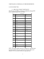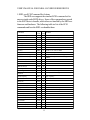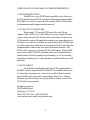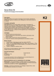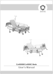
1
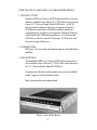
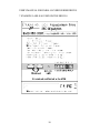
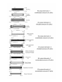
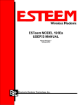
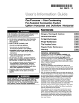
USER’S MANUAL
SRD Series
SCSI Replacement Drives
LIMITED WARRANTY
Paralan Corporation (Paralan) warrants this product (Product) to be free of defects in material and
workmanship for an initial period of two (2) years from date of delivery to the original purchaser
(Purchaser) from Paralan.
Repair or Replacement. Paralan’s obligation under this warranty is limited to replacing or
repairing, at its option and at its facilities, any of the Products (except expendable parts thereof) that
within the warranty period are returned to Paralan and that are found by Paralan to be defective in
proper usage. Repair parts and replacement Products will be either new or reconditioned, at Paralan’s
sole discretion and furnished on an exchange basis with any replaced parts or Products becoming the
property of Paralan. In the event that Paralan determines, in its sole discretion, that the returned
Product is not defective, Purchaser shall pay a testing and handling fee of seventy-five US Dollars
($75.00) per unit tested. Products returned must be delivered to Paralan’s facility, or to an authorized
Paralan service representative, with all included parts and accessories as originally shipped, along with
proof of purchase and a Return Merchandise Authorization (RMA) number. The RMA number is
obtained, in advance of shipment, from Paralan’s Customer Service Department and is valid for thirty
(30) days. Purchaser will be responsible and liable for any missing or damaged parts.
Non-Paralan Products or Parts.
Paralan is not liable for any defects in material or
workmanship of any products or parts which Paralan does not design or manufacture, including but not
limited to power supplies and cables. However, Paralan will honor the original manufacturer’s warranty
for these products or parts. In the event that Paralan determines that any defect is not related to a
Paralan manufactured Product, at Purchaser’s request Paralan shall repair or replace the defective parts
at Purchaser’s cost and deliver the defective parts to Purchaser.
Abuse or Misuse . This limited warranty shall not apply if the Product has been misused,
carelessly handled, defaced, modified or altered, or if unauthorized repairs have been attempted by
others. Any such damage shall not be considered a defect.
Costs of Shipping. In order to obtain warranty service, the Product must be delivered to
Paralan’s facility, or to an authorized Paralan service representative. The RMA number must be clearly
marked on the exterior of the original shipping container or equivalent. Purchaser agrees to pre-pay
shipping charges one way, and to either insure the Product or assume the liability for loss or damage
during transit. In the event that Paralan determines that a Paralan Product is defective, Paralan will
pre-pay transportation charges back to Purchaser.
Limitation of Implied Warranties . THE FOREGOING WARRANTIES ARE IN LIEU OF
ALL WARRANTIES, EITHER EXPRESSED OR IMPLIED, INCLUDING WITHOUT LIMITATION
ANY IMPLIED WARRANTY OF MERCHANTABILITY OR FITNESS FOR A PARTICULAR
PURPOSE, AND OF ANY OTHER OBLIGATION ON THE PART OF PARALAN.
LIMITATION OF LIABILITY. PARALAN SHALL NOT BE LIABLE TO PURCHASER, TO
ITS CUSTOMERS OR TO ANY OTHER PERSON FOR ANY INJURY OR DAMAGE TO PERSONS
OR PROPERTY, OR FOR ANY LOSS OF OR INJURY TO BUSINESS, EARNINGS, PROFITS OR
GOODWILL SUFFERED BY ANY PERSON, INCLUDING PURCHASER AND ITS CUSTOMERS,
CAUSED DIRECTLY OR INDIRECTLY BY THE PRODUCTS SOLD PURSUANT TO THIS
AGREEMENT; AND IN NO EVENT SHALL PARALAN BE LIABLE FOR ANY INDIRECT,
INCIDENTAL OR CONSEQUENTIAL DAMAGES SUFFERED BY PURCHASER, ITS CUSTOMERS
OR ANY OTHER PARTY, WHETHER SUCH LIABILITY ARISES FROM A CLAIM BASED ON
CONTRACT, WARRANTY, TORT OR OTHERWISE, EVEN IF PARALAN SHALL HAVE BEEN
ADVISED OF THE POSSIBILITY OF THE SAME. ANY PROVISION HEREIN TO THE CONTRARY NOTWITHSTANDING, IN NO EVENT SHALL PARALAN’S LIABILITY EXCEED THE
ACTUAL AMOUNT PAID BY PURCHASER TO PARALAN FOR SUCH PRODUCTS.
Ship to: Paralan Corp. 4655 Ruffner Street San Diego, CA 92111
USER’S MANUAL FOR PARALAN’S SRD SERIES DRIVES
NOTE: This equipment has been tested and found to comply with
the limits for a Class A digital device, pursuant to Part 15 of the
FCC Rules. These limits are designed to provide reasonable protection against harmful interference when the equipment is operated in a commercial environment. This equipment generates, uses,
and can radiate radio frequency energy and, if not installed and
used in accordance with the instruction manual, may cause harmful
interference to radio communications. Operation of this equipment
in a residential area is likely to cause harmful interference in which
case the user will be required to correct the interference at his own
expense.
For continued compliance, SRD-xxx customers are responsiblefor
ensuringcompliancewith their enclosure.
1
USER’S MANUAL FOR PARALAN’S SRD SERIES DRIVES
PARALAN CORPORATION
4655 Ruffner Street
San Diego, CA. 92111
TEL: (858)560-7266
FAX: (858)560-8929
E-MAIL: [email protected]
Copyright 2010 Paralan Corporation
All Rights Reserved
PRINTED IN THE UNITED STATES OF AMERICA
NOTICE:
PARALAN CORPORATION MAKES NO WARRANTY
OF ANY KIND WITH REGARD TO THIS MATERIAL, INCLUDING, BUT NOT LIMITED TO, THE IMPLIED WARRANTIES OF MERCHANTABILITYAND FITNESS FOR A
PARTICULARPURPOSE. Paralan Corporation shall not be liable
for errors contained herein or for incidental or consequential damages in
connectionwith the furnishing,performanceor use of this material.
This document contains proprietary information which is
protected by copyright. All rights are reserved. No part of this
document may be photocopied, reproduced or translated to another
language without the prior written consent of Paralan Corporation.
The informationin this documentis subjectto change without
notice.
2
USER’S MANUAL FOR PARALAN’S SRD SERIES DRIVES
TABLE OF CONTENTS
1. INTRODUCTION .................................................................. 4
1.1 Definitions .................................................................. 4
1.2 Description ................................................................. 4
2. HANDLING AND STATIC DISCHARGE PRECAUTIONS .. 5
3. SPECIFICATIONS ................................................................. 6
4. SCSI CONNECTOR .............................................................. 7
5. SRD-xxx SCSI COMMANDSET ACTIONS ........................ 8
6. Trouble Shooting ...................................................................... 9
6.1 LVD SCSI controllers ................................................ 9
6.2 SCSI cables ............................................................... 9
7. EXAMPLE LABELAS USED ON THE SRD-250 ............... 10
3
USER’S MANUAL FOR PARALAN’SSRD SERIES DRIVES
1. INTRODUCTION
Paralan’s SRD-xxx Narrow SCSI Replacement Drive uses an
industry standard state of the art 2.5” SATA drive and converts
it into a 3.5” Narrow Single Ended SCSI drive. As SCSI
drives become hard to get and grow in expense, Paralan’s
SCSI Replacement Drive will still be readily available at a
reasonable price. Replace your old and or failing SCSI drives
with Paralan’s SCSI ReplacementDrives. Use the best that
SATA has to offer for your SCSI storage. SCSI may be old,
but your storage will be new.
1.1 DEFINITIONS
SRD-xxx: The xxx is the unformated capacity of the hard drive
installed.
1.2 DESCRIPTION
Paralan Model SRD-xxx Narrow SCSI Replacementdrives
use an industry state of the art 2.5” SATA drive and converts it
to a 3.5” Narrow Single Ended SCSI Drive.
Complete specifications and a product overview are available
under “Support” on the Paralan website:
http://www.paralan.com/support.html
Rear view of the drive
4
USER’S MANUAL FOR PARALAN’S SRD SERIES DRIVES
2. HANDLINGAND STATIC-DISCHARGEPRECAUTIONS
After unpacking, and before installation, the drive may be
exposed to potential handling and electrostatic discharge (ESD) hazards. Observe the following standard handling and static-discharge
precautions:
Caution:
Keep the drive in the electrostaticdischarge bag (ESD) until
you are ready for installation to limit the drive’s exposure to ESD.
Before handling the drive, put on a grounded wrist strap, or
ground yourselffrequentlyby touching the metal chassis of a computer
that is plugged into a grounded outlet. Wear a grounded wrist strap
throughoutthe entire installation procedure.
Handle the drive only by its edges or frame.
The drive is fragile--handle it with care. Do not press down on
the drive top cover.
Always rest the drive on padded, antistatic surface until you
mount it in the computer.
Do not touch the connector pins or the printed circuit board.
Do not remove the factory installed labels from the drive or
cover them with additional labels. Removal voids the warranty. Some
factory installed labels contain information needed to service the drive.
Other lables are used to seal out dirt and contamination.
5
USER’S MANUAL FOR PARALAN’S SRD SERIES DRIVES
3. SPECIFICATIONS
INTERNAL DRIVE
Supports 2.5” SATA I and SATA II HDDs
ENVIRONMEN TAL:
Rel. Humidity
Oper. Temperature
Storage Temperature
0 - 95% non-cond.
0 - 50 degrees C
-25 - +75 degrees C
AGENCY APPROVALS:
UL, CSA, TUV/VDE, CE
EMI/RFI
MEETS FCC Class A, CE
SRD-xxx PHYSICAL DIMENSIONS:
Depth
5.7 in. (146 mm)
Width
4 in. (101 mm)
Height
1 in. (25 mm)
CONNECTIONS :
SRD-xxx
SCSI-2 50-pin non-shielded,
low-density, SCSI device
connector (A-Cable)
COMMUNICATION:
SRD-xxx Parallel Trans.
Limited by device transmissio n
rates and cable lengths. Can
transmit and accept 20
MBYTE/SEC SCSI signals.
Protocols
SHIPPING WEIGHT
ANSI X3T10 SCSI Standards
Committee SCSI-2 specifications.
3 lbs
UNIT WEIGHT
0.75lbs
6
USER’S MANUAL FOR PARALAN’S SRD SERIES DRIVES
4. SCSI CONNECTOR
4.1 SRD SCSI CONNECTOR PINOUTS
The following is the SRD-xxx50 pin non-shielded low-density SCSI
device connector from SCSI-2 (A-Cable):
SINGLE ENDED
Pin
Signal
Pin
Signal
1
GROUND
2
-DB0
3
GROUND
4
-DB1
5
GROUND
6
-DB2
7
GROUND
8
-DB3
9
GROUND
10
-DB4
11
GROUND
12
-DB5
13
GROUND
14
-DB6
15
GROUND
16
-DB7
17
GROUND
18
-PARITY
19
GROUND
20
GROUND
21
GROUND
22
GROUND
23
RESERVED
24
RESERVED
25
OPEN
26
TERMPWR
27
RESERVED
28
RESERVED
29
GROUND
30
GROUND
31
GROUND
32
-ATN
33
GROUND
34
GROUND
35
GROUND
36
-BSY
37
GROUND
38
-ACK
39
GROUND
40
-RST
41
GROUND
42
-MSG
43
GROUND
44
-SEL
45
GROUND
46
-C/D
47
GROUND
48
-REQ
49
GROUND
50
-I/O
NOTE: The single ended connector’s odd pins are ground except
for pin 25 which is left open, with pin 23 and pin 27 Reserved.
Many SCSI-2 devices have the Reserved pins grounded.
7
USER’S MANUAL FOR PARALAN’S SRD SERIES DRIVES
5. SRD-xxx SCSI Command SetActions
The SRD-xxx supports the standard SCSI command set for
narrowsingle ended SCSI drives. Some of the commandsare passed
to the SATA drive to handle, while others are handled by the SRD-xxx
firmware and hardware. The following table is a list of the SCSI
commands and how the SRD-xxxhandles them.
Comma nd
Te s t Unit Re a dy
Re ze ro
Re que s t S e ns e
Forma t Unit
Re a s s ign Blocks
Re a d(6)
Write (6)
S e e k(6)
Inquiry
Inquiry (EVP D=1,P a ge =83h)
Inquiry (EVP D=1,P a ge =80h)
Mode S e le ct(6)
Re s e rve
Re le a s e
Mode S e ns e (6)
Sta rt/Stop Unit
S e nd Dia gnos tic
P re ve nt/Allow Me dium
Re mova s
Op
S ATA
C ode Action Re ma rks
00 h
N Re turns che ck conditon a fte r re s e t
01 h
N Alwa ys re tuns s ta tus good
03 h
N
04 h
Y Write s 0x00 to firs t524,288 blocks
07 h
N
08 h
Y
0Ah
Y
0Bh
Y S e nds "s e e k 70h" to HDD
12h
Y S e nds "Ide ntify ECh" to HDDfor informa tion
12h
N Re s ponds withe the S RD bridge Info.
e nds "Ide ntify ECh" to the HDD, ge t s e ria l
12h
Y S
numbe r
15h
Y
16h
N
17h
N
1Ah
Y
1Bh
Y
1Dh
N Alwa ys re tuns s ta tus good
1E h
N
Alwa s y re turns s ta tus good
Re a d Ca pa city
25h
Y
S e nds "Ide ntify de vice ECh" to the HDD,
ge ts ca pa city
Re a d(10)
Write (10)
S e e k(10)
Write a nd Ve rify
Ve rify
S ynchronize Ca che
Re a d De fe ct Da ta
Write Buffe r
Write Buffe r (C DB1=0x11)
Write Buffe r (CDB1=0x17)
Re a d Buffe r
Re a d Buffe r (CDB1-0x17
Mode S e ns e (10)
Re port LUNs
28h
2Ah
2Bh
2E h
2Fh
35h
37h
3Bh
3Bh
3Bh
3C h
3C h
5Ah
A0h
Y
Y
Y
Y
Y
Y
N
N
N
N
N
N
Y
N
8
S e nds "s e e k 70h" to HDD
S e nds "Re a d a nd Ve rify" to HDD
S e nds "Flus h ca che Eyh/EAh" to HDD
USER’S MANUAL FOR PARALAN’S SRD SERIES DRIVES
6. TROUBLE SHOOTING
The SRD-xxx series SCSI ReplacementDrives are factory set
for ID0, with the internalSCSI terminatorON and powered internally.
If the SRD-xxx is to be connected to the middle of the SCSI bus then
the termination enable jumper must be removed.
6.1 LVD SCSI CONTROLLERS
When using LVD capable SCSI controller cards like the
AdaptecAHA-29320 series, if the SRD-xxx is not recognized by the
system, please check the SCSI controllercard settings. In most cases,
LVD controller cards will change their settings to accommodate narrow
SCSI devices on the bus, but there are some features that LVD has that
may affect operations which may need to be turned off. Turn off packet
communications,and in some cases turn off domain validation. Also
LVD is able to operate over longer SCSI cable lengths. When a SRDxxx is used with a LVD SCSI controller, make sure to limit the cable
lenth to under 20 feet if operatingAsynchronously, or 9 feet if running
faster thanAsynchronous. Contact Paralan Corporation if there are still
problems.
6.2 SCSI CABLES
Verify that the total length used on the SCSI segment that has
the SRD-xxx is no longer than 9 feet if the SCSI communicationsis set
for faster then Asynchronous. Some early models of Spark workstations should not have the cable segmentlonger than 5 feet. Contact
Paralan Corporation if there are any questions or if there is a need for
SCSI cables in your system.
Paralan Corporation
4655 Ruffner Street
San Diego, CA 92111
(858) 560-7266 Fax: (858) 560-8929
www.paralan.come-mail: [email protected]
9
USER’S MANUAL FOR PARALAN’SSRD SERIES DRIVES
7. EXAMPLE LABLE AS USED ON THE SRD-250
10
4655 Ruffner Street
San Diego, CA92111
(858) 560-7266 Fax: (858) 560-8929
www.paralan.com e-mail: [email protected]