1
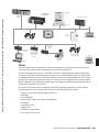
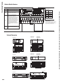
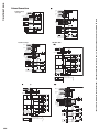
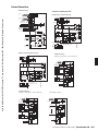
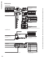
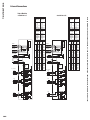
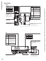
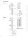
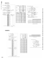
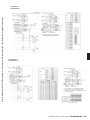
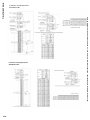
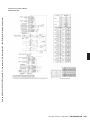
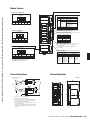
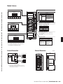
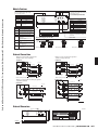
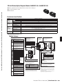
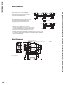
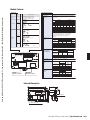
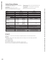
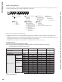
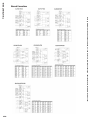
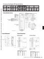
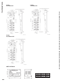
Here it is explained how to connect the AJ65BT-RPI10A/10B to the CC-Link system with the CC-Link dedicated
cables. Remove the terminal block protection cover of the
modules beforeperforming the wiring work.
Terminal
resistor
Master module
AJ65BT-RPI-10A/10B
Remote module
DA
DA
DA
DB
DB
DB
DG
SLD
FG
DG
DG
CC-Link dedicated
cable
Important
CC-Link dedicated cables with the same specifications should
be used within each segment. Normal data transmission
cannot be guaranteed if multiple specifications are used.
SLD
FG
Lens
surface
CC-Link dedicated
cable
SLD
FG
Wireless transmission
Terminal
resistor
Lens
surface
DA
DA
DB
DB
DG
DG
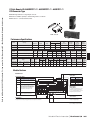
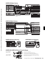
Point
SLD
CC-Link dedicated
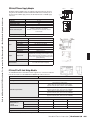
• Make sure to connect a terminal resistor to the modules
cable
FG
at both ends of a segment. Terminal resistors should also be connected
between DA and DB. (Terminal resistors are supplied with the module.)
AJ65BT-RPI-10A/10B
• The terminal resistors used vary according to the type of cable used.
For more information, see the user's manual for the master module to be used.
• The shielded wire of the CC-Link dedicated cable should be connected to "SLD" of each module, and
both sides should be treated with Class D grounding (Class 3 grounding) via "FG." Note that SDL and
FG areconnected within the module.
SLD
FG
Local module
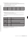
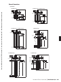
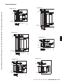
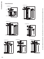
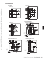
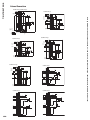
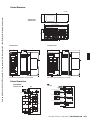
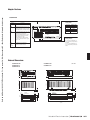
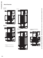
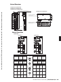
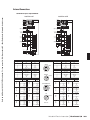
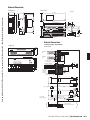
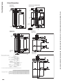
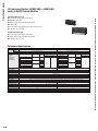
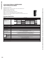
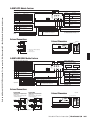
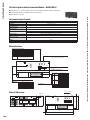
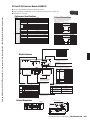
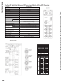
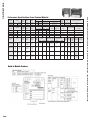
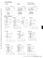
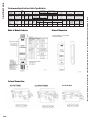
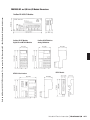
Module Dimensions
Ø mounting hole (for M6 mounting screw)
Three Ø 7mm x 16mm mounting holes (for M6 mounting screws)
B RATE
S
C
7 8
5
0
2 3
100.0
84.0
40.0
ST NO.X10
7 8
0
5
LRUN
2
LERR
3
2 3
ST NO.X1
7 8
ERR
R
C
1
SD1
RD1
SD2
0
5
PW
1
45.0
44.0
2
RD2
2 3
3
35.5
57.5
8.0
130.0
145.0
161.0
128.0
Ø 42
12.0
2.0
35.5
Optical axis adjustment angle
±4° for both left/right and up/down
394
Terminal
resistor
Unit: mm
Terminal
resistor
Sold by AA Electric 1-800-237-8274 Lakeland, FL • Lawrenceville, GA • Greensboro, NC • East Rutherford, NJ www.A-Aelectric.com
n DISTRIBUTED I/O
Module Connection