1
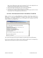
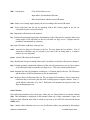
SINGLE – 04 “TFM” R.J. ANGEL Crystallography Laboratory, Dept. Geological Sciences, Virginia Tech, Blacksburg, VA24060, USA http://www.crystal.vt.edu/crystal/ INTRODUCTION SINGLE04 is a program written by RJ Angel (Virginia Tech Crystallography Lab) to carry out the calculations necessary for controlling a four-circle Eulerian-cradle diffractometer. It is developed from earlier versions of SINGLE written LW Finger (Geophysical Laboratory, CIW) and RJ Angel. Much of the code is derived from software written earlier by L.W. Finger and some of the interface code for the AMS motor controllers was provided by Bob Downs. The software is currently supplied on a non-commercial basis. The author would therefore appreciate acknowledgement of the use of the code being made in all publications that make use of data collected or processed using SINGLE. Relevant literature is: The SINGLE code itself and many of the algorithms used - Angel RJ, Downs RT, Finger LW (2001) High-Temperature-High-Pressure Diffractometry. In Hazen, R.M., Downs, R.T. (Eds.), High-pressure, high-temperature crystal chemistry. Reviews in Mineralogy and Geochemistry, 41, 559-596. The peak centering algorithms are described in Angel et al., J. Appl. Cryst., 30, 461-466 (1997). The method of diffracted beam centering (otherwise known as 8-position centering) used in the ZREF utility was originally developed by Hamilton. The practical implementation was first described by King and Finger ( J. Appl. Cryst., 12, 374-378; 1979) SINGLE04, USER MANUAL: 1 RJ ANGEL MARCH 2006 The method of constrained vector least-squares to obtain cell parameters in the CLSQ utility was developed by Ralph and Finger ( J. Appl. Cryst., 15, 537-539; 1982) While the authors are pleased to receive reports of bugs in the code and suggestions for changes and improvements, the authors take no responsibility for any incorrect operation of the code. The authors accept no liability for damage caused through use of this code to control equipment. GENERAL PRINCIPLES The program is written to be mainly diffractometer-independent. It can also be run without a diffractometer attached. This option can be selected by the user upon starting the program, and is indicated by the command line prompt of the program including the string "DMSINGLE". The circle conventions and parities, and axial systems of Busing and Levy (1967) are used for all calculations. When all circles are at their zero positions: • the 2θ arm lies in the position of the undiffracted direct beam (2θ = 0) • the plane of the χ circle is perpendicular to the direct beam (ω = 0) • the φ-axis is perpendicular to the diffraction plane (χ = 0) • the choice of φ = 0 is arbitrary. These conventions also define the "normal-beam equatorial geometry" of Arndt and Willis (1966) subsequently generalised by Dera and Katrusiak (1998). In these zero positions the Cartesian basis of the “φ-axis” coordinate system (Busing and Levy 1967) has its axes defined as follows: • the origin is at the centre of the diffractometer. • the positive y-axis extends from the crystal towards the detector (i.e. along the undiffracted direct beam), • the positive z-axis is parallel to the φ axis, perpendicular to the diffraction plane, and away from the φ-axis carrier, • the positive x-axis makes a right-handed set, and corresponds to an imaginary diffraction vector at 2θ = 0. The sense of positive rotations of the four diffractometer circles under the Busing and Levy (1967) convention are left-handed for all axes except for the χ-axis. To be explicit, when viewed from the +z direction (looking down on the diffractometer from above), positive movement of the 2θ, ω and φ axes away from their zero positions is clockwise. When viewed from the +y direction (looking towards the crystal from the detector arm) positive movement of the χ-axis is anti-clockwise. These senses of rotations are defined as having positive parities. SINGLE04, USER MANUAL: 2 RJ ANGEL MARCH 2006 FILES The SINGLE software uses several files. They are all Ascii files that can be read by any text editor such as Notepad or Wordpad. They can become corrupted if opened with a utility such as Word. The files are: 1. difprof.dat. Holds two types of information. First, diffractometer-dependent parameters such as motor drive information. Further details of these parameters are given in the installation guide. They should not normally be changed. The difprof.dat file also contains default parameters for centering scans and for data collections. These parameters are only used when a new mat file is created at startup of the Single software. Difprof.dat must reside in the same directory as the single executable. 2. single.log. The instrument log file. Resides in the same directory as the single executable. Created by Single. Holds any warning or error messages generated by the program. Do not edit as it provides a permanent record of instrument errors. 3. mat file. Contains all of the information related to the individual experiment on one crystal, including the experiment title, the UB matrix, wavelength and scan parameters, the indices, setting angles and intensities of reflections used in centering, data collection parameters. The file name extension must always be “.mat”. The file can reside anywhere, but best not with the single executable. Note: If an old matfile is opened (at start-up or later) all of the scan parameters etc are loaded from the file. If a new matfile is created when starting the Single program, the parameters are loaded immediately from the values in difprof.dat. If a new matfile is created with the set matfile command, then all of the current parameters are written to the new file, not the ones in difprof.dat. The matfile is immediately rewritten with the current parameters whenever the parameters or peak list information is changed (e.g. upon centering). 4. User log file. Created by Single, and given the same name as the mat file but with the extension .log. Resides in the same directory as the mat file. All of the information on the terminal screen (input and output) is copied to this file as a permanent record of the expeirment. Can be examined while the program is running, or afterwards, by a text editor such as Wordpad. 5. Centering scans file. Created by Single, and given the same name as the mat file with “_cntr.rfl” added. Resides in the same directory as the mat file. A standard-format reflection file containing the step-scan data of the final omega scans from centering with the zref command. Also other omega scans if log is activated. Can be used by WinIntegrStp to examine and refit the profiles after the experiment. 6. Data collection file. Created by user with the set datfile command. Can reside anywhere. A standard-format reflection file containing the step-scan data collected during a data collection. 7. Reflection list file. Created by user with a text editor. Can reside anywhere.Contains a list of reflection indices, one reflection per line, to be collected with the intl command. SINGLE04, USER MANUAL: 3 RJ ANGEL MARCH 2006 RUNNING THE PROGRAM WITH THE DIFFRACTOMETER 1. Double-click on the Single shortcut on the desk top: Single04.ico 2. Start the Single program from the shortcut on the desktop 3. A small dialogue box appears; answer “YES” to the question about running a “real” diffractometer. The main window will appear. In the scrolling region of the window, the following messages will appear in order: a. “OPENING COMMUNICATIONS ON COM1 ....please wait ”. b. “Opened COM1” (If this does not appear, you have a windows system problem) c. “Checking motor positions, please wait:” d. For each motor you should see either “OK” or a message to say that the stored position in the controller does not match the park position. 4. Then the diffractometer positions and shutter state will be updated on the display, and a file browser will appear. 5. Use the browser to select the data directory where you want to store your mat file. 6. Type in the name for the experiment (“mat”) file, or select an existing file. Do not use an extension. SINGLE04, USER MANUAL: 4 RJ ANGEL MARCH 2006 7. The program will now load some parameters and the window should look something like this: The program is now ready for your commands (see section below). If the previous user did not exit the Single software with the exit command, then the physical positions of the diffractometer will not be those of the park position, and an error message will have appeared. If this happens, check that the positions shown on the display match the physical positions of the diffractometer circles and slits. If not, correct with ldmt. The Single GUI - You can type commands in to the terminal window by clicking anywhere in the window with the left mouse button, and then typing commands. Output from the Single software also appears in this window, just like an “old-fashioned” terminal! There is no “type-ahead” buffer. You have to wait for the program to be ready to read your commands before typing them in. Be patient! When the diffractometer is busy, the terminal area will be grey, and no commands can be entered. On the upper part of the display there are two sections: On the right side is information about the current diffractometer activity (the current action, SINGLE04, USER MANUAL: 5 RJ ANGEL MARCH 2006 shutter status, diffractometer angles and slit positions). The hkl values displayed here are calculated from the displayed angles with the current UB matrix. On the bottom right are listed the names of the current mat and data files. The behaviour of the counter display depends on the installation. On the left side is a display of the last completed scan, with the angles and hkl at which it was performed. This is only updated at the end of the scan. RUNNING THE PROGRAM WITHOUT THE DIFFRACTOMETER Single can also be used to perform diffractometer calculations without being connected to a diffractometer. To start in this “DMSINGLE” or “dummy” mode, answer “NO” to the question about running a “real” diffractometer at the start of the program. After selecting the mat file the window should look something like this: This version of the program will accept all commands except those that drive the diffractometer. Even if you are using the code in dummy mode the single executable must be accompanied by a difprof.dat file for the machine for which you wish to do calculations. SINGLE04, USER MANUAL: 6 RJ ANGEL MARCH 2006 COMMANDS Diffractometer Control Commands that control the diffractometer are only accessible if the computer is connected to a diffractometer. In DMSINGLE they are disabled. cent - Perform 1-position centering of the reflection currently in the detector window. If centering is successful the user is asked whether the resulting setting angles should be added to the reflection list. clsh - close the shutter cntr - Perform 2-position centering (at +2theta and -2theta) of the reflection currently in the detector window. If centering is successful the user is asked whether the resulting setting angles should be added to the reflection list. coun- Perform a static count for 5 seconds at the current position. cpos - reports current positions of the goniometer circles. demo – drives the diffractometer around a preset list of positions. driv - drive the diffractometer to the last set of angles produced by CALC, if they were valid angles. dvls - drive the diffractometer to the setting angles of a reflection in the list, if they are valid angles. User input: number of a reflection in the list. filt - set the filter wheel, if present. goto – input four angles and drive to that position. halt - stops the diffractometer drives. See local instructions for exact action. half - set half-slits on detector arm, if present. ldmt - redefines the current physical position of a motor to the value input by the user.User input: motor number, angle value. WARNING: Take care not to enter an incorrect value as this may later cause physical collisions of the diffractometer. Take care redefining omega on diffractometers using absolute omega values - the safe method is to drive both 2theta and omega to values which you wish to define as zero. mot - direct drive of individual motors. User input: motor number, target angle. The motors are numbered as follows: 1 = 2theta, 2 = omega, 3 = chi, 4 = phi. If diffracted-beam motorised slits are installed, those defining the opening in the omega-2theta plane are motor 6, the SINGLE04, USER MANUAL: 7 RJ ANGEL MARCH 2006 perpendicular set are motor 5. opsh - open the shutter. Consult local instructions as to action when the shutter is prevented from opening, for example by safety circuits. park - drive the diffractometer circles to the park position. prof - performs step scan of any diffractometer circle about the current position and outputs measured profile to the screen. The user is prompted for the motor number, step size, number of steps and count time per step. ref - performs 2-position centering on reflections in the list whose use flags are set to 1. Updates the setting angles in the list for each successfully centred reflection. For failures the angles in the list are left unchanged, and the use flag set to 0. view - positions the diffractometer so that the sample can be viewed. See local instructions for exact action. zero - drives all of the diffractometer circles to zero. zref - performs 8-position centering on reflections in the list whose use flags are set to 1. Centering parameters can be reset with the SET CENT command. The slit settings on the detector are also defined by the parameters entered in SET CENT. The user specifies whether the starting position for the centering process for each reflection is taken as the angles from the list, or is calculated from the indices in the lost and the current UB matrix. For the purposes of instrument alignment it is possible to request zref to continue with a set of 8 equivalents after centering failures. This option should not be used for routine measurements. The true angles of each refelction are determined from the eight equivalents by the method of King and Finger ( J. Appl. Cryst., 12, 374-378; 1979) and are put in to the reflection list. The reflection list intensity is the mean value of the intensity at each of the eight positions. For failures the angles in the list are left unchanged, and the use flag set to 0. The crystal offsets reported by zref are defined on the Busing-Levy phi-axis system (see above). The value of these offsets is the displacement of the crystal from the centre of the goniometer. Thus, to correct for a reported negative offset along the y-axis, the crystal must be moved away from the X-ray source. The circle zero errors reported by zref are the apparent values of the angles when the motor controller has set the angle to zero. Therefore to correct a circle zero errors: • use mot to drive to the reported zero error. • use ldmt to redefine this position as zero. SINGLE04, USER MANUAL: 8 RJ ANGEL MARCH 2006 Reflection List Manipulation and Crystallographic Operations Crystallographic operations are performed upon the reflection list and upon the UB matrix (which also contains cell parameter information). The reflection list consists of up to 60 reflections. Each reflection entry consists of a list number, hkl, setting angles, the numbered of centred positions, a use flag, and the intensity. The list number is only the position of the reflection data in the list - some operations such as DEL or SORT lead to reallocation of list numbers to reflection data. The use flags are set with the USE command, and unset with the OMIT command. Data entry into the reflection list may be made either by some of the commands INH, INA, or IND, or as the result of centering reflections on the diffractometer (CENT or CNTR). Reflection indices may be input as command arguments as integers or reals. They are stored and manipulated by the program as reals, except when then are rounded to the nearest integer for calculations with COM, LSQ and CLSQ. angl - calculate from the setting angles the angles between all reflections in the list with their use flags set to 1. calc - calculates the setting angles of a reflection, hkl input by user. cell - input of cell parameters by the user. Blank angle fields are set to 90o. clsq - Perform symmetry-constrained refinement of the unit-cell parameters by the method of vectorleast-squares by using the indices and setting angles of all reflections in the list with their use flags set to 1. The method used is that of Ralph and Finger ( J. Appl. Cryst., 15, 537-539; 1982) com - calculate UB matrix from the unit cell parameters and two reflections in the list, selected by the user in terms of the list numbers. Before using this utility the user should have indexed the reflections with INDL. Note that COM rounds off the indices of reflections to the nearest integer. del - delete reflections from the list, as selected by list number. Sets of consecutive reflections may be selected by the end of the set being input as a negative number (see USE). List numbers of specific reflections left in the list are changed. ina - Input a set of setting angles into the list. Indices in the list are calculated from the current UB matrix. ind - Input a set of indices and setting angles into the list. indc - perform an automatic indexing with all reflections in the list with their use flags set to 1. An alternative algorithm to AUTO. SINGLE04, USER MANUAL: 9 RJ ANGEL MARCH 2006 indl - 3 sub-options: Clear all list indices to zero. Input indices for individual reflections. Index all reflections with the current UB matrix. indx - Index a set of setting angles input by the user according to the current UB matrix inh - Insert reflections into the list by inputting indices hkl. Setting angles in the list are calculated from the current UB matrix. list - Outputs the reflection list to the terminal. lsq - Perform unconstrained least-squares determination of the UB matrix by using the indices and setting angles of all reflections in the list with their use flags set to 1. Outputs unit-cell parameters unconstrained by symmetry. om - input UB matrix, with three values per line. omit - unset the use flags of reflections in the list. The user inputs the list numbers. Sets of consecutive reflections may be selected by the end of the set being input as a negative number (see use command). prom – lists the UB matrix on the terminal. sort - Reorders the list into ascending 2theta order. List numbers of specific reflections are changed. tlsq - Perform symmetry-constrained refinement of the unit-cell parameters to only the 2theta angles of all reflections in the list with their use flags set to 1. This code written by Bob Downs. tran - transform the unit-cell parameters according to a 3x3 matrix input by the user. The UB matrix and the indices of all list reflections may also be transformed. use - set the use flags of reflections in the list. The user inputs the list numbers. Sets of consecutive reflections may be selected by the end of the set being input as a negative number. Thus 4,-7 would indicate reflections 4,5,6, and 7. Reflections with numbers not input have their use flags unchanged upon exit. Data Collection Data collection parameters such as scan type, width, step size, 2theta limits etc are chosen with set data. This information is displayed on the terminal when any of these commands is input, and before the data collection starts. Data is stored as step scans in an ASCII file selected with the set datfile utility. inta - initiate a data collection scan over a set of reflections. Indices are generated by the program SINGLE04, USER MANUAL: 10 RJ ANGEL MARCH 2006 subject to the limits provided by the user in SETU ints - initiate a data collection scan over single reflections. The user is prompted for the hkl of each reflection in turn. intl- initiate a data collection scan over a list of reflections. The list may be either an ASCII file with one set of hkl per line, or the reflections in the reflection list whose use flags are set to 1. psi- perform a psi scan of a single reflection. General Utilities The utility commands include: - note to make notes into the log file - log to provide extra logging facilities, especially for debugging - set to set many parameters including centering, data scan parameters etc - show to display parameters SINGLE04, USER MANUAL: 11 RJ ANGEL MARCH 2006 COMMAND LIST SUMMARY In this list the “arguments” column details the arguments that can be entered on the same line as the command itself. If no argument is given the program will provide a prompt for the required input. Many commands will also issue questions for the user to answer. Command ANGL CALC CELL CENT CLSH CLSQ CNTR COM COUN CPOS DCOM DEL DEMO DRIV DVLS EXIT FILT GOTO HALF HALT HELP INA IND INDC Description calculate from the setting angles the angles between all reflections in the list with their use flags set to 1. calculates the setting angles of a reflection input of cell parameters by the user. Blank angle fields are set to 90o. Perform 1-position centering of the reflection currently in the detector window. close the shutter Perform symmetry-constrained refinement of the unit-cell parameters by the method of vector-least-squares by using the indices and setting angles of all reflections in the list with their use flags set to 1. Perform 2-position centering (at +2theta and -2theta) of the reflection currently in the detector window. calculate UB matrix from the unit cell parameters and two reflections in the list Perform a static count for 5 seconds at the current position. Reads motor positions from motor controller direct control of the interface. For experts only! delete reflections from the list, as selected by list number. Sets of consecutive reflections may be selected by the end of the set being input as a negative number. List numbers of specific reflections left in the list are changed. drives the diffractometer around a preset list of positions. drive the diffractometer to the last set of angles produced by CALC, if they were valid angles drive the diffractometer to the setting angles of a reflection in the list, if they are valid angles. parks the diffractometer and exits from the program set the filter wheel, if present. drive to requested angles set the half-slits if present stops the diffractometer drives Provides a list of commands Input a set of setting angles into the list. Indices in the list are calculated from the current UB matrix. Input a set of indices and setting angles into the list. perform an automatic indexing with all reflections in the list SINGLE04, USER MANUAL: 12 Arguments none h,k,l a,b,c,α,β,γ none none crystal-system number (1-6) none two list numbers none none none list numbers none none list number none filter number 2θ, ω, χ, φ T=top, B=bottom, L=left, R=right O=open none none none none none RJ ANGEL MARCH 2006 INDL INDX INH INTA INTL INTS LDMT LIST LOG LSQ MOT NOTE OM OMIT OPSH PARK PROF PROM PSI REF with their use flags set to 1. 3 sub-options: Clear all list indices to zero. Input indices for individual reflections. Index all reflections with the current UB matrix. none Index a set of setting angles input by the user according to the current UB matrix Insert reflections into the list by inputting indices hkl. Setting angles in the list are calculated from the current UB matrix. setting angles initiate a data collection scan over a set of reflections. Indices are generated by the program subject to the limits provided by the user in set data initiate a data collection scan over a list of reflections. The list may be either an ASCII file with one set of hkl per line, or the reflections in the reflection list whose use flags are set to 1. initiate a data collection scan over single reflections. The user is prompted for the hkl of each reflection in turn redefines the current physical position of a motor to the value input by the user. Outputs the reflection list to the terminal. initiate logging of profile and centering information either to the terminal or to a file. none Perform unconstrained least-squares determination of the UB matrix by using the indices and setting angles of all reflections in the list with their use flags set to 1. Outputs unit-cell parameters unconstrained by symmetry. direct drive of individual motors. Allows text to be typed on the terminal to be echoed to the user logfile, without being interpreted as commands. Exit from the utility by typing EXIT on a line on its own. input UB matrix, with three values per line. Unset the use flags of reflections in the list. The user inputs the list numbers. Sets of consecutive reflections may be selected by the end of the set being input as a negative number. Thus 4,-7 would indicate reflections 4,5,6, and 7. Reflections with numbers not input have their use flags unchanged upon exit open the shutter drive the diffractometer to the preset park positions performs step scan of any diffractometer circle about the current position and outputs measured profile to the screen prints the current UB perform a psi scan of up to 30 reflections. performs 2-position centering on reflections in the list whose use flags are set to 1. Updates the setting angles in the list for each successfully centred reflection. For failures the angles in the list are left unchanged, and the use flag set to SINGLE04, USER MANUAL: 13 none none none motor number, angle none none none motor number, angle none none list numbers none none none none none none RJ ANGEL MARCH 2006 SET CENTER SET DATA SET DATFILE SET DEVICE SET LOG SET MATFILE SET TITLE SET WAVE SHOW CENTER SHOW DATA SHOW DATFILE SHOW DEVICE SHOW DEVTYPES SHOW LOG SHOW MATFILE SHOW TITLE SHOW UB SORT 0. Input parameters for centering reflections Input data collection parameters Open a file for storing scans from data collection Select diffraction geometry and restrictions due to devices (eg DAC) Set logging options Select mat file Input a title Input wavelengths List parameters for centering reflections none none none none none none none none List data collection parameters Print name of the file for storing scans from data collection none none Show the selected diffraction geometry and restrictions none List all available device types none Show logging options Print the name of the mat file none none Print the title Print the UB matrix Reorders the list into ascending 2theta order. List numbers of specific reflections are changed. Perform symmetry-constrained refinement of the unit-cell parameters to only the 2theta angles of all reflections in the list with their use flags set to 1. none none none TRAN transform the unit-cell parameters according to a 3x3 matrix input by the user. The UB matrix and the indices of all list reflections may also be transformed. none USE set the use flags of reflections in the list. The user inputs the list numbers. Sets of consecutive reflections may be selected by the end of the set being input as a negative number. Thus 4,-7 would indicate reflections 4,5,6, and 7. Reflections with numbers not input have their use flags unchanged upon exit drives diffractometer so that the sample can be viewed with the telescope Drives the diffractometer circles to zero Performs 8-position centering on reflections in the list whose use flags are set to 1. Updates the setting angles in the list for each successfully centred reflection. For failures the angles in the list are left unchanged, and the use flag set to 0. list numbers TLSQ VIEW ZERO ZREF crystal-system number (1-6) none none none The following commands available in earlier versions have been discontinued: SINGLE04, USER MANUAL: 14 RJ ANGEL MARCH 2006 Command Description AUTO Perform an automatic indexing with all reflections in the list with their use flags set to 1. The resulting unit-cell is normally reduced. The reflections are indexed. BRAV CALP Cell reduction routine calculates the 2theta and chi angles of a reflection from the coordinates of spots on a rotation photograph Perform a cone search Orientation of crystal faces with respect to the telescope performs static intensity measurements at points of a grid defined in reciprocal space Perform rotation photo scan, starting from preset photo position Turn printer on and off. Perform a linear scan in reciprocal space Search for reflections CONE FACE GRID PHOT PRNT SCAN SRCH ERRORS Errors in the program or the diffractometer are of two levels: WARNING: Non-fatal error which the software will either ignore or attempt recovery. Examples are: - individual failures in communications - failure to open shutter - failure to open files - software failures (unusual results, failure of least-squares) - failure of user to specify necessary information - problems reading the mat file. The program will log the warning to the user log, the terminal, and the instrument log. If communication or instrument problems continue, a fatal error will be logged. If they are cleared, then the program will issue a message noting the recovery, that again will be logged to the user log, the terminal, and the instrument log FATAL ERROR: Examples are: - failures in reading the difprof.dat file - diffractometer limit switches active - shutter failure after 5 attempts - persistent error in communications. These force the program to stop, request acknowledgement from the operator, and return the program to the main prompt to allow appropriate action to be taken by the operator. Fatal errors are logged to the user log, the terminal, and the instrument log. Persistent fatal errors should be investigated before they lead to damage to the diffractometer! SINGLE04, USER MANUAL: 15 RJ ANGEL MARCH 2006 SPECIAL BAYREUTH HUBER OPERATION NOTES 1. Motors are 1=2theta, 2=omega, 3=chi, 4=phi, 5=vertical aperture, 6=horizontal aperture. 2. Motor drives are in degrees, slits in mm. For centering the usual slit sizes are motor5=1mm, motor6=9mm 3. The program works with omega values as the deviation from bisecting. The omega values displayed by the SMC-9000 are absolute omega: om(abs)=om(bi)+theta. 4. WARNING: Take care redefining omega with ldmt. The safe method is to drive both 2theta and omega to physical zero, and then use ldmt to set 1,0 and 2,0 in this order. 5. To stop the Single program during a measurement: Open the radiation enclosure. Wait. The next time the program issues a command to open the shutter, it will display an error message. When you select “OK” the program will return to the Single prompt. Then you should enter the cpos command to ensure that the program has the correct angles loaded from the interface. 6. If a motor limit switch is activated by the diffractometer, the single program will detect the limit switch and halt with an error message. When you select “OK” the program will return to the Single prompt. It is critical that you now complete the following instructions: a. Clear the error flag from the SMC-9000 controller by pushing the “RESET” button. If the “limit switch” message reappears on the SMC-9000 then the limit switch is still active and you will have to move the diffractometer manually to clear the switch, and then RESET again. b. Read the physical positions of the diffractometer circles and the slits from the odometers. c. The RESET clears the motor positions from the SMC-9000 controller. Use the ldmt command to reload the correct physical positions of the circles and slits into the SMC-9000. Remember to allow for the fact that the SMC-9000 displays omega as absolute, whereas Single uses omega relative to bisecting. d. When you have loaded all six motor positions with ldmt drive each circle to zero with the mot command. Watch the diffractometer carefully because if you made an error in step b or c you will have a collision. Check the odometer. If the motor is not at physical zero, reset the position with ldmtr. Continue until the motor is at physical zero, and the position displayed by both the SMC-9000 and Single is zero. Do the axes in this order: phi, then chi, then 2theta, then omega. e. When all circles are zeroed, check the motion of the slits by driving them to other non-zero values. Do not drive the slits to zero! f. If all appears ok, try calc and driv to a known reflection position. 7. The “counts” display on the GUI normally shows the maximum from the last scan that was performed unless the coun command is used, in which case the measured count rate is displayed. SINGLE04, USER MANUAL: 16 RJ ANGEL MARCH 2006 SPECIAL VTX HUBER OPERATION NOTES 1. Motors are 1=2theta, 2=omega, 3=chi, 4=phi, 5=vertical aperture, 6=horizontal aperture. 2. Motor drives are in degrees, slits in mm. For centering the usual slit sizes are motor5=1mm, motor6=9mm 3. The program works with omega values as the deviation from bisecting. The motor controller uses absolute omega: om(abs)=om(bi)+theta. 4. WARNING: Take care redefining omega with ldmt. The safe method is to drive both 2theta and omega to physical zero, and then use ldmt to set 1,0 and 2,0 in this order. 5. If a motor limit switch is activated by the diffractometer, the single program will detect the limit switch and halt with an error message. When you select “OK” the program will return to the Single prompt. Then: a. Read the physical positions of the diffractometer circles and the slits from the odometers and compare them to the values displayed on the Single GUI. b. If necessary, reinitialise the motor controllers with ldmt. c. Drive the motors to zero and recheck the odometer values. d. When all circles are zeroed, check the motion of the slits by driving them to other non-zero values. Do not drive the slits to zero! e. If all appears ok, try calc and driv to a known reflection position. SINGLE04, USER MANUAL: 17 RJ ANGEL MARCH 2006