1
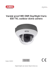
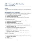
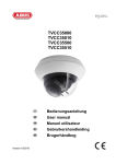
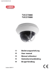
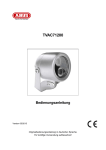
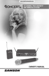
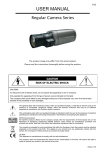
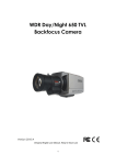
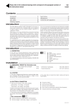
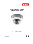
For this camera type the camera module can be
removed, and it is fixed by two fixing screws. Base part
of the camera and camera module are connected by a
15 pin D-Sub joint. Unscrew the fixing screws, and
carefully remove the camera module.
Place the base part to the desired installation
position, mark the holes for fixing on the
surface, and drill the fixing holes. Use the
supplied screws and pegs to fix the base part on
the surface. The cable rounting can be done to
the side or throught the base.
Flush mounting
For flush mount of this analog indoor dome
camera an optional flush mount bracket is
available (TVAC31010).
2
First remove the base cover ring by using a thin
flat screw driver. Carefully move the screw
driver into the small openings at the outside of
the dome bottom part, and push the screw
driver to the center of the dome (image, marking
1/2/3). The 3 fixing elements will be loose now,
and the base cover ring can be removed
carfully.
1
3
Now drill a hole of 124 mm into the ceiling panel
(max. 130 mm). Plase the flush mount bracket
onto the ceiling panel, and move the camera
bottom part into the hole. Please use the
supplied screws to fix the camera bottom part
with the ceiling mount bracket (see image).
The cable routing will be performed through the
ceiling.
25