1
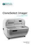
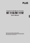
Wireless Interactive Panel
UPIC-56M/UPIC-64M/UPIC-W72M
System Operating Instructions
(detailed version)
We greatly appreciate your purchase of this PLUS Wireless Interactive Panel.
To be sure to make the most of this product’s functions, read this “System
Operating Instructions (detailed version)” carefully before using the panel. After
reading, store the manual in a safe place for future reference.
These System Operating Instructions are for use with the UPIC-56M, UPIC-64M, UPICW72M magnet type wireless interactive panels. The system consists of a digital pen, panel
and software.
• The panel sizes differ for models 56, 64 and W72. The descriptions in this manual are
for the UPIC-56M.
The software applications for this product are UPIC Utility and UPIC Touch&Draw, compatible with Windows Vista SP1 (32-bit) and Windows XP SP3 and later (32-bit). The software
will not operate on other operating systems.
Trademarks
• Microsoft and Windows are registered trademarks or trademarks in the United States and other
countries of the Microsoft Corporation of the United States.
• Adobe and Adobe Acrobat Reader are trademarks of Adobe Systems Incorporated.
• Anoto® is a registered trademark of the Anoto Group AB.
• Bluetooth and the Bluetooth logo are registered trademarks of Bluetooth SIG, Inc.
Note that PLUS fully respects trademarks of corporations and products, even when not specially
mentioned.
Other product and company names in this manual are registered trademarks or trademarks of the
respective corporations.
(1) Reproduction of the contents of this manual, in full or in part, is prohibited.
(2) The contents of this manual are subject to future change without notice.
(3) The contents of this manual have been prepared with utmost care. If, however, you should notice
any dubious points, errors or omissions or you should have any comments, please contact PLUS.
(4) Please note that PLUS will accept no responsibility whatsoever for any damages, loss of earnings
or other claims resulting from the use of this product, regardless of item (3) above.
Contents
Important Safety Information............................................................................................ 5
Description of the wireless interactive panel..................................................................... 8
Package contents.............................................................................................................. 9
Part Names and Functions.............................................................................................. 10
Panel..........................................................................................................................................10
Digital pen...................................................................................................................................11
Operation of the digital pen and indicator............................................................................11
Loading the battery into the digital pen.......................................................................................12
Replacing the stylus....................................................................................................................12
Flow of preparations prior to using the wireless interactive panel and when quitting.... 13
Installing the wireless interactive panel........................................................................... 14
Mounting the panel.....................................................................................................................14
Putting the panel away................................................................................................................15
Installing the Software..................................................................................................... 16
Before installing...........................................................................................................................16
Operating environment........................................................................................................16
UPIC Touch&Draw operation...............................................................................................16
Updating UPIC Touch&Draw...............................................................................................16
Copyright and License................................................................................................................17
Installing UPIC Utility and UPIC Touch&Draw...............................................................................18
Check before installing........................................................................................................18
Installing UPIC Utility and UPIC Touch&Draw.......................................................................18
Uninstalling UPIC Utility and UPIC Touch&Draw..........................................................................19
Pairing the digital pen and computer.............................................................................. 20
Registering on Windows XP........................................................................................................20
Registering on Windows Vista.....................................................................................................22
Connecting the computer and projector......................................................................... 24
Starting up UPIC Utility................................................................................................... 25
Calibrating the projector..............................................................................................................25
Changing the calibration setting..................................................................................................26
Starting up and quitting UPIC Touch&Draw.................................................................... 27
Starting up UPIC Touch&Draw....................................................................................................27
Quitting UPIC Touch&Draw.........................................................................................................28
Continued on next page
UPIC Touch&Draw Part Names and Functions............................................................... 29
Projected image (computer screen).............................................................................................29
Toolbar........................................................................................................................................30
Drawing Shapes.........................................................................................................................33
Moving, enlarging/reducing and rotating objects.........................................................................34
Outline of UPIC Touch&Draw Operations....................................................................... 35
Basic Operations of UPIC Touch&Draw.......................................................................... 37
List of error messages..................................................................................................... 40
Table of digital pen indicator operations......................................................................... 40
Troubleshooting............................................................................................................... 41
Technical support................................................................................................................41
Specifications.................................................................................................................. 42
Important Safety Information
Before using
Symbols Explained
Various symbols are used in this manual included with this product and on the product itself to ensure
safe use of the product and to prevent injury to the user and others as well as damage to property.
These symbols and their meanings are described below. Be sure to understand them fully before proceeding with your reading of the manual.
• Also read the cautions on safety in the operating instructions for the projector, computer and
Bluetooth USB adapter connected to the computer, and be sure to use these products properly as
well.
Meaning of symbol
Examples of symbol
This symbol notifies of instructions urging caution (includCaution – risk of electric
ing both danger and warnings). A more concrete indicator
shock
of the type of caution is shown inside the symbol.
This symbol notifies of prohibited actions. A more concrete indicator of the type of prohibited action is shown
Disassembly prohibited
inside the symbol.
This symbol notifies of actions that are restricted or
Unplug the power cord
instructions. A more concrete indicator of the instruction
from the power outlet.
is shown inside the symbol.
CAUTIONS
[Panel]
Keep magnetic recording media away from the panel.
The magnetic panel (models UPIC-56M, -64M and -W72M) has a magnetic sheet attached
to it and magnets under the surface in the four corners. Do not allow magnetic recording
media such as credit cards, transport passes, floppy disks, video tapes or cassette tapes
near the panel surface or holding bars. Allowing such objects come within 10 cm could
result in damage to the recorded data.
About projectors
This system uses a projector to project images. Your eyes may be exposed to the light from
the projector during presentations, etc.
Be careful, as looking directly into the light from the projector could damage your eyes.
Check that the screen remains in place immediately after mounting it.
Immediately after mounting the screen, check that it does not peel off the surface of installation when you release the holding bars.
Do not touch the edges of the main unit panel.
When installing or storing the panel, be careful not to cut your hands on the edges of the
panel.
Continued on next page
Do not use the included CD-ROM in a CD player for audio discs.
Never use the included CD-ROM in a CD player for audio discs. Doing so will produce loud
sounds which could injure your ears or damage your speakers.
Additional Cautions
[Panel]
About the place of installation
Do not install in the places described below. Doing so may warp the panel and decrease its
functionality.
• Hot places exposed to direct sunlight
• Places exposed to the direct wind from air-conditioners
• Near heating appliances, heaters, etc.
• Places exposed to soot or humidity (near kitchen counters, humidifiers, etc.)
Do not scratch the panel.
Do not hit or poke the panel with sharp or hard objects. Also, do not bend the panel or roll it up
with wrinkles in it. Doing so could make it impossible for the digital pen to be read and result in
malfunctioning.
Do not clean the panel with chemicals.
Do not clean the panel using thinner, benzene, alcohol or other such chemicals. Doing so may cause
discoloration or damage the panel, making it impossible for the digital pen to be read and resulting in
malfunctioning.
When using markers (ink)
Be sure to use only the included exclusive markers and exclusive eraser. Using other markers or erasers or rubbing the panel directly with your hand could result in ink stains that cannot be removed.
Always store the markers horizontally. If markers are not stored horizontally, it may be difficult to erase
the ink.
Do not leave any markings made on the panel using the exclusive markers for a long period of
time.
Doing so may make it difficult to erase the ink.
Do not apply adhesive tape, etc., to the panel.
Doing so could make it impossible for the digital pen to be read and result in malfunctioning.
[Others]
Do not use a Bluetooth USB adapter on a USB hub.
Operation is not guaranteed when a USB hub is used on the computer.
Handling the CD-ROM
Do not touch the surface with no label printed on it (the surface on which data is recorded). If the surface on which the data is recorded is dirty, the data cannot be read off the disc properly. Also, do not
paste any paper, stickers, etc., onto the CD-ROM.
Do not leave in places exposed to direct sunlight or near heating appliances for extended periods of
time, and do not drop or bend. Doing so could warp the CD-ROM, making it impossible to read its
data.
LED RADIATION
DO NOT VIEV DIRECTLY
WITH OPTICAL INSTRUMENTS
CLASS I LED PRODUCT
Disposal of Waste Equipment by Users in Private Household in the European Union
( Applicable in the European Union and other European countries with collection systems )
This symbol on the product or on its packing indicates that this product should
not be treated as household waste. Instead it should be delivered to the applicable
collection point for the recycling of electrical and electronic equipment. By ensuring this product is disposed of correctly, you will help prevent potential negative
consequences for the environment and human health, which could otherwise be
caused by inappropriate waste handling of this product. The recycling of materials
will help to conserve natural resources. For more detailed information about recycling of this product, please contact your local city office, your household waste
disposal service or the shop where you purchased the product.
Note: This symbol mark is for EU countries only.
This symbol mark is according to the directive 2006/66/EC Article 20
Information for end-users and Annex II.
This symbol means that batteries and accumulators, at their end-of-life, should be
disposed of separately from your household waste.
Cleaning
Dots for detecting the coordinates are printed on the panel. If the panel surface is dirty, it
may not be possible for the digital pen to be read and malfunction could occur.
Perform the cleaning operations below periodically.
Cleaning of the panel
Clean the surface of the panel with the panel mounted on the board (wall) surface. Attempting to clean
the surface of the panel with the panel placed on the floor could cause dirt or dust from the floor to get
stuck on the magnetic layer on the panel’s back surface, decreasing the adhesive strength against the
surface of installation and causing the panel to fall off.
If the panel is dirty, wipe it off with a damp, thoroughly wrung out cloth. For tough dirt, apply a little
clean water to the sponge of a new exclusive eraser, wipe clean, then before the panel dries wipe
again with a soft, dry cloth. After cleaning, wait until the panel has dried completely before using.
Do not use heavily soiled erasers, moist wipes, office cleaners, neutral detergents, etc.
When cleaning the back surface of magnet type panels, remove the dirt or dust gradually, rolling the
panel up on the holding bar as you go. When rolling up the panel, be careful not to wrinkle or crimp it.
About the eraser
If the eraser’s erasing surface is dirty, purchase a new eraser.
Using a dirty eraser could result in getting dirt on the panel that is hard to get off.
Description of the wireless interactive panel
A computer and projector are required to use the wireless interactive panel.
A wireless interactive panel is a system using a computer, projector and the ADP-301 digital pen*1 as the writing tool, allowing users to write and draw on a panel electronically just
as if they were actually writing and drawing on the panel. The wireless interactive panel can
be used for effective presentations during conferences, speeches and educational events.
*1 “ADP-301 digital pen” hereafter referred to simply as “digital pen”.
[Wireless interactive panel]
National Sales Figures
[Digital pen]
Transmitted to computer
Projection
National Sales Figures
[Computer]
[Projector]
Input/output, image processing, storing and printing are performed on the computer. The words
and figures drawn on the panel are transferred to the computer in real time using Bluetooth wireless
technology built into the digital pen, then re-projected onto the panel from a projector serving as the
display device.
Thus, it appears that the user is actually writing directly on the panel.
• It is possible to save the image from the computer projected onto the panel (the background) combined with the words and figures drawn on the panel as well as pasted images, or, by switching
to the white screen mode, the image can be saved without the background. This makes it easy to
reuse and distributed the saved data.
• The panel can be used as a regular whiteboard using the included markers (ink).*2
*2 Words and figures drawn with the markers (ink) cannot be saved on the computer or projected.
Erase them using the included eraser.
Package contents
• Panel: 1 unit
A sheet-type panel with coordinates printed on it.
Magnet type panels (M) can be rolled up for storage or
carrying.
• Digital pen (model DP-301): 1 set
(Including 1 spare stylus and 1 AAA alkaline battery)
This pen is used to write words and figures on the
panel and to operate the computer wirelessly using
UPIC Touch&Draw*.
* In this manual, the wireless interactive panel’s
software application is referred to as either “UPIC
Touch&Draw” or “the software”.
• Exclusive markers (black and red: 1 each)
The exclusive markers (ink) can be used to draw
directly on the panel, when using the system as a
whiteboard.
• Exclusive Eraser: 1
This is used to erase words and figures drawn directly
on the whiteboard using the exclusive markers (ink).
• Exclusive carrying case: 1
This case can be used for storing and carrying the
main unit panel and accessories.
* Always store the main unit panel in its paper tube
(sleeve).
• Documents
• System Operating Instructions (simple version):
1
This manual includes information on points to be heeded to ensure safe use as well as basic descriptions of
the system’s main operations.
It also includes instructions for installing the system
and for installing the “UPIC Utility” driver for the digital
pen as well as the UPIC Touch&Draw software stored
on the included CD-ROM.
• Digital pen operating instructions: 1
This includes instructions to be heeded to ensure safe
use.
• CD-ROM: 1
This includes UPIC Utility, UPIC Touch&Draw and the
System Operating Instructions (detailed version) (in
PDF format).
Part Names and Functions
Panel
A panel on which coordinates are printed in dot pattern. It is written on using the digital
pen. The panel is also used as the screen on which images are projected.
Panel (front)
Holding bars
Panel (back)
The entire back surface has a magnetic sheet structure, allowing the panel to be mounted
on commercially available whiteboards (in steel) and steel panels with smooth, flat
surfaces.
* A “flat panel” refers to a panel with a flat, smooth surface.
10
Digital pen
This is the writing tool for drawing on the panel. When drawing on the panel, the position
and pen pressure information is transmitted wirelessly to the computer in real time.
Pen cap
This protects the digital pen and turns its power on and off.
The power turns on when the cap is taken off the tip of the
pen and turns off when the cap is put on.
Indicator
The indicator lights or flashes to indicate the digital pen’s
connection, standby status, etc.
Battery cover
Remove this to change the battery.
Power on/off notch
When the cap is put on, the notch is pressed in, turning the
power off.
NOTE Be careful not to press the notch by mistake
when using the pen. Doing so will turn the power
off.
Infrared reading sensor
This reads the coordinates printed on the panel.
Stylus
This is linked to the pen pressure sensor.
• Operation of the digital pen and indicator
When using for the first time, you must pair the computer and digital pen.
* Pairing refers to establishing the wireless connection between the computer and digital pen.
See “Pairing the digital pen and computer” on page 20.
1.When the cap is removed, the digital pen’s power turns on (the indicator flashes) and connection to
the computer begins.
2.Once the connection is completed, the indicator turns off and the pen input standby mode is set.
In this mode, the digital pen can be used to draw and click.
3.When the cap is put on, the power turns off.
NOTICE
Check that the digital pen is properly registered on the computer, that the digital pen is not too far
from the computer (within 10 meters), and that the digital pen’s battery is not worn out (the pen’s
indicator flashes slowly). If the battery is worn out, the software’s icon in the computer’s task tray
changes. Check the battery power on the display that appears when the icon is clicked.
Cautions on Use
• Do not place the digital pen at an excessively strong angle when drawing, or it will not be able to
properly read the coordinates.
• Do not leave the digital pen’s cap off. Doing so will wear down the battery.
• Do not try to use the digital pen with the stylus removed. The pen will not operate unless the
stylus is mounted.
11
Loading the battery into the digital pen
1. Slide the cover lock downwards to unlock the cover.
Open the battery cover.
2. Remove the old battery, then insert the new battery in the
proper direction, lining up the + side with the indication in
the “battery case”.
3. Insert the hook on the cover in the groove in the “battery
case”, close the battery cover, then slide the cover lock
upwards to lock the cover.
NOTICE
When replacing the battery, use a commercially available
AAA alkaline battery.
NOTE
Rechargeable batteries cannot be used.
Replacing the stylus
If the stylus should wear down or get bent, replace it with the included spare stylus.
1. Grasp the stylus (the round pen tip) and pull it straight off.
2. Insert the new included spare stylus straight onto the pen
tip until it stops.
12
Flow of preparations prior to using the wireless interactive panel and when quitting
NOTICE
When using a computer on which steps 1 and 2 have been completed, start the preparations
from step 3.
1
Install on the computer UPIC Utility and UPIC Touch&Draw from the
included CD-ROM. (See page 18.)
2
Make the computer recognize the digital pen (pairing). (See page
20.)
* A commercially available Bluetooth USB adapter is required if the computer is not
equipped with the Bluetooth function.
3
Install the wireless interactive panel. (See page 14.)
4
Connect the computer and projector. (See page 24.)
5
6
Calibrate the positions of the computer and projector. (See page 25.)
The wireless interactive panel can now be used.
Start up the software. (See page 27.)
On the computer, select [Start] → [All Programs] → [UPIC] → [UPIC Touch&Draw] to start up
the software.
• Once you are finished using the wireless interactive panel
1. Close the software. (See page 28.)
2. Put the cap on the digital pen.
The digital pen’s power turns off.
3. Shut down the computer.
4. Turn off the projector’s power.
• Moving and storing
1. Disconnect the computer and projector.
2. Put away the wireless interactive panel. (See page 15.)
13
Installing the wireless interactive panel
The back surface of the wireless interactive panel (referred to simply as “the panel” below)
is a magnetic layer. Mount it on a metal surface that will not yield when force is applied.
Below are some examples for your reference.
• Whiteboard (in steel)
• Steel wall or steel panel
Mounting the panel
This description is for mounting the panel on a whiteboard (in steel).
For proper mounting, this procedure should be performed by two people.
1 Clean the surface of installation.
Before mounting, wipe clean the surface on which the panel is to be mounted. Any dirt, pieces
of cellophane tape, etc., will cause the panel surface to be uneven. If you wipe the surface with a
damp cloth, wait until it dries.
2 Attach the panel flatly against the surface of installation.
With the panel still rolled up, line it up carefully.
Now, unwind the holding bar to the left or right, attaching the panel flatly to the mounting surface
(making sure no air remains between it and the surface of installation) as you go. If after mounting
any air is still trapped, eliminate it by wiping the panel gently with a piece of cloth, etc.
NOTE
• Check that the panel is securely mounted and does not come off.
• To reattach it, first wind it up onto the holding bar, then start over.
14
Putting the panel away
Carefully clean the panel’s surface before putting the panel away. If this is not done, dust or
dirt could get on the panel’s back surface when the panel is rolled up, reducing magnetic
effect.
1 Roll up the panel.
Roll the holding bar onto the paper tube used in the package, then roll up carefully, pressing the
holding bar against the board surface and being careful that there is no looseness in the roll and
that the roll does not get crooked.
Paper tube
Holding bar
NOTE
• When rolling up the panel, apply enough pressure to keep the panel from falling away from the
surface on which it is mounted. If you release the panel in the middle of the rolling up process,
the panel will fall.
• Do not roll too tightly. Doing so could cause creases in
the panel surface or cause the panel to curl.
[Correct]
[Incorrect]
• Attempting to correct for crookedness by force while the panel is partially rolled up on the holding bar could damage the panel. If there is any skewing, unroll the panel completely then start
over.
• Do not remove the panel from the surface upon which it is mounted with the panel unrolled.
Doing so will cause the panel to crease, making it impossible for the digital pen to be read and
resulting in malfunction.
• Be careful not to cut your hands when touching the edges of the panel.
15
Installing the Software
Before installing
• Operating environment
Item
Operating system
Description
Windows Vista (SP1 or later, 32-bit version)
Windows XP Home/Professional (SP3 or later, 32-bit version)
Ver. 5.0 or later
Pre-installed computer on which one of the above operating systems
is running
Pentium 4 processor or later
Conforming to Bluetooth 2.0 Class 2
512 MB or greater
200 MB or greater
1024 × 768 High Color or greater
Bluetooth adapter
CD-ROM drive, standard USB port
Microsoft® Bluetooth® stack
Broadcom’s Widcomm® Bluetooth® software stack
Toshiba Bluetooth® stack
BlueSoleil Bluetooth® stack
Internet Explorer
Computer
CPU
Interface
Memory
Hard disk
Display
Peripherals
Compatible Bluetooth
stacks
NOTE
• Providing the above operating environment does not guarantee that all operations will work.
• Not compatible with Macintosh.
• When using a computer with no built-in Bluetooth function, a free port for connecting a
Bluetooth USB adapter is required.
• UPIC Touch&Draw operation
UPIC Touch&Draw and UPIC Utility are independent. Because of this, operation differs as
follows depending on which applications are started up.
UPIC Utility
UPIC Touch&Draw
○
○
○
×
×
×
○
×
Pen connection
status
Connected
Not connected
Connected
Not connected
—
—
• Updating UPIC Touch&Draw
See the PLUS website at: www.plus-vision.com/en/
16
Operation
UPIC Touch&Draw can be started up
UPIC Touch&Draw cannot be started up
Digital pen usable as mouse
—
UPIC Touch&Draw cannot be started up
Not possible
Copyright and License
• Copyright
PLUS Vision Corp. (hereafter called We) holds the copyright of this software and related works which
are protected by Japan’s Copyright Law and international treaties.
Copyright © Since 2008 PLUS Vision Corp. All rights reserved.
• Disclaimer
We shall not be responsible in any way for direct or indirect damages that may arise from this software
or products derived from related software. We shall not be responsible in any way for damages as a
result of the machine or medium. Furthermore, We shall not be responsible in any way that may relate
to the effects of the results of using this software.
• Terms of Use and Terms of Distribution
• We shall not be responsible in any way for any kind of damages arising from the use or inoperability
of this software.
• We shall not be liable in any way for support of this software, any kind of warranty, correction of
trouble or continuation of version upgrades, etc.
• Provided that you consent to the aforementioned matters, you shall be permitted to use the software for non-profit purposes for personal use and use within a company.
• When “this software” is mentioned, it refers not only to the executable file, but to all of the component files including Help and appended text.
• Support
We call support the provision of all kinds of information including answers to questions, requests,
trouble reports, and other matters, and the scope of our support shall be limited to the functions and
operation of this software.
Problems that arise in using this software may be attributed to one of many causes, including the
personal computer, the OS, other application software, and other peripheral devices. Accordingly, we
only support problems that are attributable to this software. Also, this software is subject to version
upgrades without prior notice due to the technical advancement of hardware and software. The customer can receive and use upgraded versions of this software through a method determined by us.
Note that version upgrades will be limited to customers who consent to the aforementioned conditions
of use.
* Upon downloading this software from the PLUS Vision Web site, or installing it from the CD-ROM,
the customer is deemed to have consented to each of the terms.
17
Installing UPIC Utility and UPIC Touch&Draw
“UPIC Utility” and “UPIC Touch&Draw” are installed when “Install software” is selected from
the included CD-ROM’s menu.
• Check before installing
1.Check that the computer being used satisfies the required operating conditions.
2.When installing, do so with the authority (account) of the computer’s administrator.
3.Close any other running applications.
• Installing UPIC Utility and UPIC Touch&Draw
1
Insert the included CD-ROM into the computer’s CD-ROM drive.
A menu screen appears automatically.
If the screen does not appear automatically, open the CD-ROM folder and double-click “autorun.exe”.
2
The installer is launched.
3
Follow the installer’s instructions to
install the software.
Click “Installation of Software”.
“UPIC Utility” and “UPIC Touch&Draw” are installed
simultaneously.
• A “Customer Information” dialogue box is displayed. Check the displayed contents, then click
[Next (N)] to continue installing.
NOTICE
* For Windows Vista, a user account control
dialogue box appears. Select “Accept (A)”
to continue installing.
Continued on next page
18
4
Click [Finish].
The “Installer Information” dialogue box appears.
Click [Yes (Y)] to restart the computer.
This completes installation.
Now proceed to the operation for pairing the digital
pen and computer. (See page 20)
Uninstalling UPIC Utility and UPIC Touch&Draw
1
2
3
4
5
6
Click [Start] → [Control Panel] to display the control panel window.
• Check that the digital pen’s cap is attached and that its power is turned off.
• Check that UPIC Touch&Draw is closed.
Click “Uninstall Program”.
* For Windows XP, the “Add/Remove Program” icon appears.
The “Uninstall/Change Program” window appears.
* For Windows XP, the “Add/Remove Program” icon appears.
From the list, click “PLUS UPIC”.
For Windows Vista, click [Remove]*.
For Windows XP, click [Remove].
Follow the instructions on the screen to proceed.
NOTICE
* For Windows Vista, the user account control dialogue box appears each time the uninstaller is
launched. Choose “Accept (A)” to continue uninstalling.
19
Pairing the digital pen and computer
The digital pen is a Bluetooth device. Signal transfer between it and the computer is not
possible unless the computer has recognized the digital pen.
This section describes pairing* using the Bluetooth stack included with Windows.
* Pairing refers to the operation of connecting the digital pen and computer by wireless communication. In this manual pairing is also referred to as “connecting”.
NOTE
• Operation may be unstable when using multiple Bluetooth devices.
• When using a computer with a built-in Bluetooth function, do not use a commercially available
Bluetooth adapter. If you wish to use a Bluetooth adapter, turn off the built-in Bluetooth function. For instructions on how to do so, contact the manufacturer of your computer.
• Multiple digital pens can be connected simultaneously, but depending on the usage environment (the computer, the signal conditions, etc.), simultaneous operation may not be possible.
If the computer does not include a built-in Bluetooth device, use a commercially available Bluetooth
USB adapter. Refer to the operating instructions of your Bluetooth USB adapter for instructions on
pairing. Input “0000” as the digital pen’s path key.
NOTICE
For a description of the Bluetooth USB adapters that can be used to connect to the digital pen,
see the PLUS website. (www.plus-vision.com/en/)
Use a Bluetooth USB adapter supporting the HID (Human Interface Device) profile.
Registering on Windows XP
Preparations:
1.Turn on the Bluetooth function (the computer’s built-in function or a commercially available USB
adapter).
2.Take the digital pen’s cap off. The power turns on and the indicator lights.
1
Click [Start] → [Control Panel] to open
the control panel, then click [Printers
and Other Hardware].
The “Printers and Other Hardware” window
appears.
2
Click [Bluetooth Devices].
The “Bluetooth Devices” window appears.
Continued on next page
20
3
4
Click [Add…].
The “Add Bluetooth Device Wizard” window
appears.
Check (click) the “My device is set
up and ready to be found” checkbox,
then click the [Next (N)] button.
The next window in the add wizard appears.
5
Click “ADP-301B”, then click the
[Next (N)] button.
The next window in the add wizard appears.
6
Choose (click) the “Use the passkey
found in the documentation (U)” radio
button, input “0000” as the path key,
then click the [Next (N)] button.
The next window in the add wizard appears.
7
Click the [Finish] button.
Continued on next page
21
8
Put the cap on the digital pen.
The digital pen’s power turns off.
To register multiple digital pens, repeat the above procedure. When doing so, input “0000” as
the path key.
Now when the digital pen’s cap is removed, the digital pen automatically connects to the
computer and the pen input standby mode is set.
Registering on Windows Vista
Preparations:
1.Turn on the Bluetooth function (the computer’s built-in function or a commercially available USB
adapter).
2.Take the digital pen’s cap off. The power turns on and the indicator lights.
1
Click [Start] → [Control Panel] to
open the control panel, then click
[Hardware and Sound].
The “Hardware and Sound” window appears.
2
3
Click [Bluetooth Devices].
The “Bluetooth Devices” window appears.
Click [Add…].
The “Add Bluetooth Device Wizard” window
appears.
Continued on next page
22
4
Check (click) the “My device is set
up and ready to be found” checkbox,
then click the [Next (N)] button.
The next window in the add wizard appears.
5
Click “ADP-301B”, then click the
[Next (N)] button.
The next window in the add wizard appears.
6
Choose (click) the “Use the passkey
found in the documentation (U)” radio
button, input “0000” as the path key,
then click the [Next (N)] button.
The next window in the add wizard appears.
7
8
Click the [Finish] button.
Put the cap on the digital pen.
The digital pen’s power turns off.
To register multiple digital pens, repeat the above procedure. When doing so, input “0000” as
the path key.
Now when the digital pen’s cap is removed, the digital pen automatically connects to the
computer and the pen input standby mode is set.
23
Connecting the computer and projector
In order to use this system, a computer and projector must be connected.
1. Install the projector in the target position.
For cautions related to installing the projector, see the projector’s operating instructions.
Check that the projector’s power is turned off.
2. Use a computer signal cable to connect the computer’s monitor terminal to the
projector’s computer input terminal.
Check that the computer’s power is turned off.
3. Turn on the projector’s power and start up the computer.
After a certain amount of time (about 30 seconds, though this depends on the projector), the
computer’s screen is projected from the projector.
• Check that the projector’s input selection is set to the connected computer.
• If the screen of a notebook computer is not projected from the projector or if the notebook
computer’s screen is off, change the computer’s external output setting.
In Windows, this is normally done by pressing one of keys [F1] to [F12] while pressing in the
function key ([Fn]). Which of keys [F1] to [F12] is pressed depends on the brand of computer.
For details, see your computer’s help file.
4. Adjust the position and size and for any distortion of the picture projected from
the projector.
Position the projector so that the picture fits on the wireless interactive panel. If the picture is distorted, use the projector’s trapezoidal (keystone) correction function (vertical/horizontal correction)
to adjust for a normal picture.
• UPIC Touch&Draw includes a function for calibrating the positions of the panel and the projected
image. If the projected image is distorted, calibration may not be performed properly.
[Wireless interactive panel]
Example of misaligned and distorted
projected image
Properly adjusted projected image
Monitor output
Computer input
Monitor
[Projector]
[Computer]
Computer signal cable
24
Starting up UPIC Utility
Calibrating the projector
Before starting up UPIC Touch&Draw, calibrate the positions of the computer and projector
(UPIC Utility). Calibration patterns are displayed automatically when the computer detects
the connection with the digital pen.
To change the connection detection method, see “Changing the calibration setting” on
page 26.
Check:
Check that the projector and computer are connected and that the computer’s screen is
being projected on the screen. (See page 24.)
NOTE
• Calibrate the position of the picture projected from the projector so that it fits on the wireless
interactive panel.
• Select the connected computer as the projector’s input.
• The digital pen’s power turns off automatically if the pen is not used for about
7 minutes with the cap off. To use it after this has happened, first put the cap
onto the digital pen, then take it back off.
1
Take off the digital pen’s cap.
The digital pen’s indicator flashes. If the indicator
remains lit without flashing, the pen is not paired
(connected) with the computer. (See page 20.)
When the computer detects the connection to the
digital pen, calibration patterns are displayed on
the wireless interactive panel and the pattern at the
upper left flashes.
NOTE
Note that this operation is canceled if the digital pen’s cap is put on.
2
Calibrate the positions of the computer and projector.
Using the digital pen, touch the center of the “+”
mark on the pattern that is flashing, pattern one at
a time. The patterns turn off once the patterns in all
four corners have been touched.
Continued on next page
25
• The pattern that is flashing switches in the following order as the patterns are touched:
Top left → Bottom left → Bottom right → Top
right
Once a pattern has been touched, it turns gray.
This completes the calibration procedure.
Next, start up UPIC Touch&Draw. (See page 27.)
Changing the calibration setting
Change the connection detection method when the projector has been moved or the size
of the projected image is changed.
1
2
With the mouse, right-click on the
UPIC Utility icon in the computer’s
task tray. A pop-up menu appears.
Select the desired item from the menu
to change the setting and calibrate.
Calibration
Calibration at Startup
Select Monitor
Help
Exit
The calibration patterns appear if the position has not been calibrated. For instructions on calibrating, see page 25. (Default)
When connection of the digital pen is detected, the calibration
patterns appear.
The operation changes by switching the calibration operation
setting check button on and off.
On (default): Calibration is performed each time at startup.
The window for selecting the number of the monitor connected
to the projector is displayed.
Select the number of the monitor connected to the projector.
By default, searching is performed with the monitor number set
to “Display 1”.
Display the UPIC Utility’s help file.
Quit UPIC Utility.
26
Starting up and quitting UPIC Touch&Draw
Starting up UPIC Touch&Draw
1
Start up UPIC Touch&Draw.
There are three ways to start up this software.
• The software can be started up by clicking
[Start] → [All Programs] → [UPIC] → [UPIC
Touch&Draw] on the computer.
• UPIC Touch&Draw can be started up by doubleclicking the software’s
icon on the Windows
desktop.
• UPIC Touch&Draw can be started up by double-clicking the file saved using the software’s
“Save” command (extension .tad).
NOTICE
• If connection to the digital pen is not possible,
the message “The digital pen is not connected. Connect the digital pen before starting up
UPIC Touch&Draw.” appears.
Click [OK] to close the message.
Once the digital pen is connected, start UPIC
Touch&Draw back up. See “Pairing the digital
pen and computer” on page 20.
27
Quitting UPIC Touch&Draw
1
Click
“Close” on the UPIC
Touch&Draw window’s toolbar.
When operating using the image projected on the
panel, click
“Close” on the toolbar.
2
UPIC Touch&Draw is closed, and
the “Confirm closing” message is
displayed.
The message differs, depending on whether or not
there is unsaved data.
If there is no unsaved data:
[Yes]
Click this to quit UPIC Touch&Draw.
[No]
Click this to cancel quitting.
If there is data that has not yet been stored:
[Yes]
When this is clicked, the Windows “Save
as” window appears. UPIC Touch&Draw
is closed after data storage is completed.
[No]
When this is clicked, UPIC Touch&Draw
is closed without storing the data.
[Cancel] Click this to cancel quitting.
3
Put the cap on the digital pen.
28
UPIC Touch&Draw Part Names and Functions
Projected image (computer screen)
Drawing area
Drawings and figures made with the digital pen as well as
read-in images are displayed here.
Toolbar
Use this to select and set the various
functions in UPIC Touch&Draw. For
details, see page 30.
The items that can be selected
depend on the mode. Items that cannot be selected are displayed in gray.
Menu layout
Move menu
Mouse
Pen
Marker
Eraser
Figure
Select Object
Task tray
Style
UPIC Utility icon
When right-clicked, a pop-up menu appears.
Calibration, Calibration at Startup, Select Monitor, Exit
(see page 26)
(When
is displayed):
When the icon is left-clicked, a pop-up menu indicating
that the digital pen’s battery power is low is displayed.
Color
Undo
Redo
Delete
Screen Mode
Insert Picture
Open
Save
Print
Close
Minimize
Help
29
Toolbar
Menu direction
Move menu
The direction of the menu bar switches between horizontal and vertical
each time this is clicked.
Drag here to move the menu to the desired position.
* Only one of the “Mouse”, “Pen”, “Marker”, “Eraser”, “Figure” and “Select
Object” icons can be selected at once. It is not possible to select multiple icons. These six functions are called input modes.
Mouse
Switches the input mode to the mouse mode.
In this mode, the computer screen projected on the panel can be
operated.
• Certain buttons on the toolbar cannot be selected when in the mouse
mode.
• Windows operations can only be performed when in the mouse mode.
• Mouse operations using the digital pen
Dragging: Move with the pen tip pressed in.
Clicking: Press the pen tip once.
* This performs the Windows left-click operation. (It is not possible to perform the rightclick operation with the digital pen.)
Double-clicking: Press the pen tip twice.
Pen
Switches the input mode to the pen mode.
Set the pen thickness at “Style”, the pen color at “Color”.
Marker
Switches the input mode to the marker mode.
Set the marker thickness at “Style”, the marker color at “Color”.
Eraser
Switches the input mode to the eraser mode.
• Use this to erase part of what you have written. Drag the eraser over
words and lines you have drawn with the digital pen to erase that section. To erase entire objects, it is faster to use the “Delete” icon.
• Set the eraser thickness at “Style”.
• Figures and images cannot be erased.
Figure
Displays the “Figure Menu” window. (See page 33.)
Click the desired figure icon and drag the digital pen to draw the figure.
• Set the figure color at “Color”, the thickness of the lines at “Style”.
• To close the “Figure Menu” window, either click the “Figure” icon on the
toolbar.
Select Object
Switches the input mode to the object selection mode. (See page 34.)
Click the object to select and move it, etc.
Style
Displays the “Style Menu” window. Use this to select the thickness of the
tool for the currently selected input mode (pen, marker, eraser or figure).
This cannot be selected when the input mode is set to the mouse or object
selection mode.
[When pen, marker or figure is
selected]
30
[When eraser is selected]
Color
Displays the “Color Menu” window. Use this to select the color for the currently selected input mode (pen, marker or figure).
This cannot be selected when the input mode is set to the eraser, mouse
or object selection mode.
Undo
Up to the last 100 drawing or editing operations can be undone in order,
starting from the most recently performed operation.
Redo
Restores the operations undone with the undo command, in order.
Delete
Displays the “Delete Menu” window. The screen turns off after the object is
deleted.
* To cancel, click somewhere outside the menu. The “Delete Menu” window turns off.
Notation: Clears letters or lines drawn with the digital pen.
Selected Object: Clears the selected object.
All: Clears everything, including images inserted with the “Insert Picture” command.
Screen Mode
The mode switches between “White Screen” and “Overlay Screen” each
time the screen mode icon is clicked.
When in the “Overlay Screen” mode : The computer’s screen is displayed on the
background. Other applications can be displayed and written on with the digital pen.
When in the “White Screen” mode : The background is a white screen with ruled
lines.
The
mouse icon cannot be selected when the white screen is
displayed.
Insert Picture
Displays the Windows “Open File” window. Images in the following formats
can be inserted: JPEG, BMP, PNG, TIFF, GIF. (See page 38.)
• Pictures can be moved, enlarged/reduced and rotated (images only).
* If the image is larger than the drawing area, it is automatically reduced,
keeping the same aspect ratio.
Open
Displays the Windows “Open File” window. Use this to open files you have
created and saved with UPIC Touch&Draw (.tad files).
* Image files saved in formats other than TAD (.tad) cannot be opened
with this command.
31
Save
Displays the Windows “Save As” window. Use this to save the drawing
area data. (See page 39.)
The format for saving the data can be selected from one of the following:
“.jpg” (JPEG format), “.bmp” (BMP format), “.png” (PNG format), “.tif” (TIFF
format) or “.tad” (TAD format)
The file name is input automatically as follows: “[product name] + [date] +
[serial number].xxx” (“xxx” being the extension for the selected file format).
* “.tad” files (in TAD format) can be opened with the “Open” command
and edited with UPIC Touch&Draw. (TAD is a file format unique to UPIC
Touch&Draw.)
This icon can only be selected when the screen mode is set to “White
Screen”.
* Files saved with the extensions “.jpg”, “.bmp”, “.png” and “.tif” can be
imported into other applications as image data.
Print
Opens the Windows “Print” window.
Select the necessary items on the print window. See your Windows
instructions.
When the screen mode is set to “Overlay Screen”, an image combining the
Windows screen background with the drawing area data is printed.
When in the white screen mode, an image combining the UPIC
Touch&Draw’s screen background with the drawing area data is printed.
Help
Displays the help menu.
Minimize
The UPIC Touch&Draw window is closed and the minimize icon is placed
on the task tray. Click this to display the UPIC Touch&Draw window as it
was before it was minimized.
Close
UPIC Touch&Draw is closed, and the “Confirm closing” message is displayed. (See page 28.)
32
Drawing Shapes
Example: Drawing a rectangular frame
1
Click
1
2
3
[Figure].
The “Figure Menu” window appears.
2
3
4
5
6
7
8
9
10
1 Sets the figure to horizontal and vertical lines (default)
2 Sets the figure to straight lines
3 Sets the figure to a rectangle
4 Sets the figure to a rectangle (filled)
5 Sets the figure to a circle
6 Sets the figure to a circle (filled)
7 Sets the figure to a horizontal/vertical
arrow
8 Sets the figure to an arrow
9 Sets the figure to a horizontal/vertical
2-way arrow
10 Sets the figure to a 2-way arrow
Click the Rectangle icon.
• To change the color, select the desired color at
the “Color Selection Menu” window.
• To change the thickness of the lines, select the
desired thickness at the “Style Menu” window.
Drag the pen from the starting point
to the end point.
When the pen is dragged, the figure is drawn from
the starting point as a dotted line, following the
movement of the pen. The figure is only entered
when the pen is lifted, so you do not have to worry
about going off course while dragging.
• Another figure can be selected while the “Figure
Menu” window is displayed.
• The “Figure Menu” window is closed when the
“Figure Menu” window or the [Figure] icon on
the toolbar is clicked.
To write letters, click the [Pen] or [Marker] icon,
then write.
33
Drag
Moving, enlarging/reducing and rotating objects
Letters and lines drawn with the digital pen, lines and figures created with the Figure tool and inserted
pictures are called “objects”.
1
2
Click the
[Select Object] icon.
• The mode for selecting objects is set.
Select the desired object.
Click
When the object is clicked, a frame is displayed.
Click anywhere outside the object to turn the frame
off.
Horizontal
point
Vertical point
The object is enlarged/reduced in
the horizontal direction.
The object is enlarged/reduced in
the vertical direction.
Equal ratio
The object is enlarged/reduced at
point
an equal ratio.
Rotation point The object is rotated (only images
can be rotated).
Rotation point
Horizontal
point
To select multiple objects, drag the pen over the
area containing the desired objects. Objects can
only be enlarged at an equal ratio.
Equal ratio
point
Vertical point
Drag
3
4
Moving objects
With the frame displayed, drag at any position
within the frame (other than a point) to move the
object.
The object can be moved anywhere as long as at
least one side of the object can still be selected (it
cannot be moved so far that it is completely disappears from the drawing area).
Enlarging/reducing and rotating
objects
With the frame displayed, drag the desired point.
The shape of the cursor changes when the cursor
is set on a point.
Drag
Drag
34
Outline of UPIC Touch&Draw Operations
1
Preparing documents
• When the screen mode is switched to the white screen mode, a white screen is
displayed.
The digital pen can be used to write in and insert diagrams into this drawing area to conduct presentations. Prepare the diagrams to be used for the presentations in advanced
on your computer.
* The formats of image files that can be inserted into the drawing area using UPIC
Touch&Draw are JPEG, BMP, PNG, TIFF and GIF.
• The Windows desktop can be projected as the background by switching the screen
mode to the overlay screen mode. You can also switch back to the white screen mode.
By using the overlay screen mode, you can write words or insert pictures in the drawing
area while projecting documents from other applications.
However, because UPIC Touch&Draw uses an image of the Windows desktop as
the background, the applications on the desktop cannot be operated using the UPIC
Touch&Draw toolbar.
To operate the application on the background
a)Select the mouse icon from the UPIC Touch&Draw’s toolbar. The mouse icon cannot be
selected while in the white screen mode.
b)Click in the window of the application displayed on the Windows desktop to bring it to the
forefront (making it operable), then operate it as desired.
* Avoid inserting images in such a way that they cover the entire drawing area. If an image
covers the entire drawing area, that image will be selected when you click in the drawing area. If this does happen, first display a different application, then return to the UPIC
Touch&Draw and switch the screen mode to the overlay screen mode.
2
Take off the digital pen’s cap and calibrate the positions of the computer and projector. (See page 25.)
3
Start up UPIC Touch&Draw. (See page 27.)
4
Select the “White Screen” or “Overlay Screen” icon from the toolbar.
5
6
Display the presentation documents using the “Insert Picture” mode.
To display a TAD file you have prepared for the presentation in advance using UPIC
Touch&Draw, click “Open” and open the desired TAD file.
Make any additional annotations using the digital pen.
* Select the desired pen or marker thickness and color to write words, etc.
* Straight lines, circles, etc., can be drawn by selecting the “Figure” icon and dragging.
Continued on next page
35
7
8
Saving
* When “Save” is selected, the format for saving the data can be selected from one of the
following: “.jpg” (JPEG format), “.bmp” (BMP format), “.png” (PNG format), “.tif” (TIFF format) or “.tad” (TAD format)
* TAD (“.tad”) is a file format unique to UPIC Touch&Draw. Files in TAD format can be
opened using the UPIC Touch&Draw’s “Open” command and edited (moving/enlarging
objects, etc.).
“.tad” (the TAD format) can only be selected when the screen mode is set to the white
screen mode.
* Files saved with the extensions “.jpg”, “.bmp”, “.png” and “.tif” can be imported into other
applications as image data.
To conduct another presentation from this point, click the “Delete”
icon, and on the “Delete Menu” window click “All” to delete all the
data, then return to step 6.
NOTE Be sure to save any important data before deleting it.
9
Quit the software. (See page 28.)
36
Basic Operations of UPIC Touch&Draw
This section describes the basic operations in UPIC Touch&Draw. For details, see the
explanations of the individual items.
These basic operations are performed after calibration is completed and UPIC Touch&Draw
has been started up. If UPIC Touch&Draw is not started up, see “Starting up and quitting
UPIC Touch&Draw” on page 27.
• The digital pen’s power turns off automatically if the pen is not used for about
7 minutes with the cap off. To use it after this has happened, first put the cap
onto the digital pen, then take it back off.
Example: Conducting a presentation in the overlay screen mode.
The operations are performed on the picture projected on the wireless interactive panel.
1
Select the [Screen Mode] icon from
the toolbar.
The screen mode set when UPIC Touch&Draw is
started up is the
[Overlay Screen] mode.
To use the white screen mode, click the [Screen
Mode] icon and switch to the
[White Screen]
mode.
2
Operate Windows to display the presentation documents over the entire
screen.
Click the
[Mouse] icon on the toolbar and open
the desired presentation file.
National Sales Figures
7000
6000
5000
4000
Amount
3000
Sales
2000
1000
0
Office A
3
Use the digital pen to write words and
figures.
Click the
[Marker] icon on the toolbar and write
with the digital pen.
To change the marker color, click the
[Color]
icon and select the desired color. To change the
thickness of the lines, click the
[Style] icon and
select the desired setting.
Continued on next page
37
Office C
Office E
Office G
National Sales Figures
7000
6000
5000
4000
Amount
3000
Sales
2000
1000
0
Office A
Office C
Office E
Office G
4
Inserting an image.
Prepare the image beforehand.
1)Click the
[Insert Picture] icon on the toolbar
to display the “Open File” window.
2)Select the desired file then click [Open]. The
“Open File” window closes and the image is
positioned at the center of the drawing area.
3)When the image is clicked after clicking the
[Select Object] icon on the toolbar, a frame is
displayed. Drag at any position within the frame
to move the object to the desired position. For
details, see page 33.
National Sales Figures
7000
6000
5000
4000
Amount
3000
Sales
2000
1000
0
Office A
5
Drawing lines
1)Click the
[Shapes] icon on the toolbar , then
on the “Shapes Menu” window click the
[Line] icon.
2)Now drag. A straight line is drawn with the position at which you started as the starting point.
• To change the thickness of the line, select the
desired thickness (in pixels) at
[Style].
3)To write freehand and draw letters, click the
[Marker] icon on the toolbar and write with the
digital pen.
To project a different Windows application
while using in the white screen mode
1)When the toolbar’s
[Minimize] icon is clicked
with the digital pen, the window is closed
temporarily.
• When minimized, Windows operations can
be performed with the digital pen.
2)Operate Windows using the digital pen to display the desired presentation document.
3)Switch back to the white screen mode.
Click the UPIC Touch&Draw icon in the
Windows taskbar to restore the window.
Continue with the presentation.
Continued on next page
38
Office C
Office E
Office G
National Sales Figures
7000
6000
5000
4000
Amount
3000
Sales
2000
1000
0
Office A
Office C
Office E
Office G
Office G
6
7
Saving the screen
1)Click the
[Save] icon on the toolbar to display
the “Save as” window.
2)Select “Save to”, and select the file type.
• The TAD format (“.tad”) can only be selected
when in the white screen mode. Files in this
format can be opened with the “Open” command and edited with UPIC Touch&Draw.
(TAD is a file format unique to UPIC
Touch&Draw.)
• When “.jpg”, “.bmp”, “.png” or “.tif” is selected, the image saved is a combination of the
image in the drawing area and the Windows
screen. Files in these formats can be loaded
into other applications as image data.
• The file name is input automatically as follows:
“[product name] + [date] + [serial number].
xxx” (“xxx” being the extension for the selected file format).
We recommend changing the file names on
the computer after quitting UPIC Touch&Draw
to names that are more easily recognizable.
3)Click “Save”.
To conduct a new presentation at this
point, first clear the drawing area.
Click the
[Delete] icon on the toolbar, then from
the “Delete Menu” window click “All” to delete all
the data.
* To cancel without deleting, click anywhere outside the “Delete Menu” window before clicking
“All”.
National Sales Figures
7000
6000
5000
4000
Amount
3000
To continue, repeat operations 1 to 6.
Sales
2000
1000
0
Office A
8
Ending the presentation
See “Quitting UPIC Touch&Draw” on page 28.
39
Office C
Office E
Office G
List of error messages
The error messages below are displayed after UPIC Touch&Draw is closed.
Item
Description
Memory error
There is not enough computer memory for UPIC Touch&Draw.
Digital pen detection The digital pen could not be detected.
error
Item
Calibration error
Low digital pen battery warning
See page ...
16
12, 20
Description
See page ...
• Adjust the projector’s position, then perform calibration again.
25, 26
• Calibration has not been properly input.
The remaining power in the digital pen’s battery is low.
12, 29
Table of digital pen indicator operations
Digital pen
Indicator operation
Description
Operation when cap First lights, then turns off Preparations for using the digital pen are completed.
Flashing (lit for 0.5 secCurrently pairing, pairing is ongoing.
is removed
onds, off for 1 second)
Off
Digital pen is not working.
• Try putting the cap back on then taking if off
again.
• Battery is low and digital pen can no longer be
used.
Flashing slowly (lit for
Battery is low.
0.5 seconds, off for 5
• Replace the battery.
seconds)
Flashing quickly (lit for
An error has occurred.
0.2 seconds, off for 0.2 • Put the cap back on, then try again.
seconds)
Operation during
Off
Digital pen is operable.
Flashing slowly (lit for
Battery is low.
use
0.5 seconds, off for 5
• Replace the battery.
seconds)
Flashing quickly (lit for
An error has occurred.
0.2 seconds, off for 0.2 • Put the cap back on, then try again.
seconds)
NOTICE
The digital pen’s power turns off automatically if the pen is not used for about 7 minutes with the
cap off. To use it after this has happened, first put the cap onto the digital pen, then take it back
off.
40
Troubleshooting
Digital pen problems
Condition
Digital pen’s indicator does not
light/flash
Check
• Is a battery inserted in the digital pen?
• Is the battery worn out?
• Is the battery inserted in the wrong direction (+ and – polarities)?
• Are you using a rechargeable battery?
• Connection to device or pairing with the digital pen has not yet
been completed. Pair the digital pen and computer.
Digital pen’s indicator flashes
(lit for 0.5 seconds, off for 1
second)
Digital pen has been recognized • Is the digital pen being used at an angle of more than 45
but pen does not write
degrees with respect to the panel surface?
• Is there adhesive tape, etc., on the panel’s surface?
Interactive panel problems
Condition
Check
It is hard to erase what you have • Has the ink been left on the panel for an extended period of
drawn with the marker.
time?
• Have you used a marker other than the exclusive markers?
• Are you wiping the panel with thinner or benzene?
Interactive panel’s adhesive
• For magnet type panels, use a dampened cloth to wipe any dirt
strength is weak.
or dust off the magnets on the backs of the holding bars and off
the panel’s back surface (the magnetic layer).
• Technical support
If the problem with the product or software cannot be solved, contact your nearest PLUS
Vision office, dealer or store.
Internet: http://www.plus-vision.com/en/support/index.html
* PLUS only accepts inquiries made using the special Inquiry Form.
41
Specifications
Model name
Type of installation
External dimensions
Weight (Not including pen or
accessories)
Panel
Size
Reading system
Digital pen*2 *3
Model name*4
Power supply
Interface
Main unit weight
Operating time
Usage conditions
Temperature
Humidity
Functions
Interactive modes
UPIC-56M
Magnetic sheet type
W1160 × D11.3 × H865 mm
(W45.7 × D0.4 × H34.1 inches) *1
Approx. 1.6 kg (3.5 lb)
UPIC-64M
UPIC-W72M
W1330 × D11.3 × H995 mm
W1630 × D11.3 × H1070 mm
(W52.4 × D0.4 × H39.2 inches) *1 (W64.2 × D0.4 × H42.1 inches) *1
Approx. 2.1 kg (4.6 lb)
Approx. 2.8 kg (6.2 lb)
W1130 × H845 mm
W1300 × H975 mm
(W44.5 × H33.3 inches)
(W51.2 × H38.4 inches)
Anoto pattern reading using Anoto pen*2 *3
W1600 × H1050 mm
(W63 × H41.3 inches)
ADP-301 (Type name: DP-301)
AAA alkali battery × 1 (1.5V)
Conforming to Bluetooth 2.0 class 2*5
Approx. 40 g (0.1 lb) (including battery)
During continuous drawing – Approx. 5 hours; In standby - Approx. 150 hours (with cap removed)
0°C to 40°C
30 to 85% (with no condensation)
White screen mode, overlay screen mode, mouse mode
Functions (pen colors (8 colors)/marker colors (8 colors)/eraser/pen, marker and eraser size selection/ insertion of pictures/deleting of page contents/screen mode selection/printing/file input/output)
Whiteboard
Marker writing
Included software operating environment
Compatible operating
XP (Home Edition /Professional Edition Service Pack 3 or later/Vista 32-bit version*6
systems
Compatible computer types Preinstalled models operating on one of the operating systems above
CPU
Pentium 4 processor or later
Memory
512MB or greater
Hard disk
200MB or greater
Display resolution
1024 × 768 pixels or greater, High Color or greater
Devices
Bluetooth adapter*7, standard computer USB port, CD-ROM drive
Compatible Bluetooth
Microsoft® Bluetooth® stack
stacks
Broadcom’s Widcomm® Bluetooth® software stack
Toshiba Bluetooth® stack
BlueSoleil Bluetooth® stack
*1: Including maximum protruding parts.
*2: A computer and projector are required to draw with the digital pen.
*3: For details on operating principles, etc., see http://www.anoto.com/
*4: Model subject to change without notice.
*5: A separate Bluetooth adapter is required to connect to a computer not equipped with a built-in Bluetooth
function.
*6: Providing the above operating environment does not guarantee that all operations will work.
*7: No Bluetooth USB adapter is included. For a list of recommended commercially available Bluetooth USB adapters, see the Products page on our website.
www.plus-vision.com/en/
• Digital pens may be purchased separately as individual articles. For details, see our website.
www.plus-vision.com/en/
However, it is not possible to use multiple digital pens simultaneously.
42
© 2009, PLUS Vision Corp.
24-4512-09A