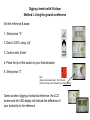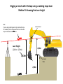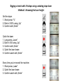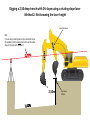
1
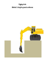
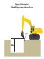
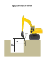
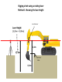
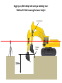
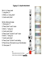
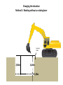
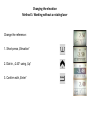
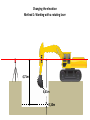
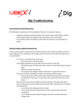
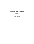
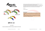
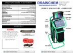
User
Manual
Applications
Manual Version: 1.00
Software Version: 1.00
Language: English
See www.ubexi.com for
more detailed information.
Safety Information: Magnets
Use caution with the powerful magnets in iDig mounting plates
The mounting plates used to secure the sensors to the excavator use extremely strong rare earth
magnets. They must be handled with care to avoid personal injury and damage to the magnets. Fingers
and other body parts can get severely pinched between two attracting magnets or other metal surface.
Use caution when removing the magnetic mounting plates from the carrying case. When handling them,
be aware of their strong attraction to any nearby steel surface (such as the other mounting plates or
metal back plates of the sensors).
Other warnings about rare earth magnets
Never allow rare earth magnets near a person with a pacemaker or similar medical aid. The strong
magnetic fields of the magnet can affect the operation of such devices.
The strong magnetic fields of rare earth magnets can also damage magnetic media such as credit cards,
magnetic I.D. cards, cassette tapes, floppy disks, video tapes or other such items. They can also
damage computer hard drives, televisions, VCRs, computer monitors and other CRT displays. Never
place rare earth magnets near electronic appliances.
Children should not be allowed to handle rare earth magnets as they can be dangerous. Small magnets
pose a choking hazard and should never be swallowed or inserted into any part of the body.
Rare earth magnets are brittle, and can peel, crack or shatter if allowed to slam together. Do not modify
or machine them. Eye protection should be worn when handling these magnets, because shattering
magnets can launch pieces at great speeds. They will lose their magnetic properties if heated above
80°C (175°F). Rare earth magnets should never be burned, as burning them will create toxic fumes.
Safety Information: Laser
SAFETY LABELS
The One-Dot Laser used for first-time setup is a Class 2 laser, manufactured to comply with
the international rules of safety IEC 60825-1, 2001. Although the power of the emission of the
beam is less than 5mW in Class 2, the following cautions are recommended:
• Do not stare directly at the beam
• Do not set up the laser at eye level
Introduction
Use the system to dig with an excavator to a desired depth and create a
leveled plane or to set a slope and create a tilted surface. Also use it to
determine reach, such as for the width of a trench.
All the digging information is referenced to the center of the bucket blade
(or teeth) and the depth value shown is the distance from the actual
teeth position to the target depth.
Sensors measure the angle of the boom, stick, and bucket. The
information is transmitted instantly to the cab display. LEDs tell you how
far to dig.
A simple one-time procedure allows the iDig system to “learn” the
dimensions of your machine. That is how it constantly calculates, in real
time, where the bucket tip is in relation to the target depth.
Excavator rotation and movement
With iDig, the operator has to dig “straight ahead” (only moving the
booms/bucket in and out).
After the target depth has been set, the chassis has to stay stable. Any
rotation of it may produce an error depending on the inclination.
Rotation of the chassis can be compensated by using a fourth sensor
as a “pitch” sensor on the chassis. This will automatically correct
forward and backward tilting movements of your machine as well as
rotation, providing accurate depth information.
Every time that the excavator tracks are moved, it’s necessary to zero
again the reference (target) depth on a previous point or, depending on
the setup, take the laser height again.
Safety Information: Radio
PRECAUTIONS
The product must not be disposed with household waste.
Dispose of the product appropriately in accordance with the national regulations in force in your country.
FCC Labels on sensors & LED Display
ELECTROMAGNETIC COMPATIBILITY (EMC)
Description
The term Electromagnetic Compatibility is taken to mean the capability of the product to function smoothly in an environment where electromagnetic radiation
and electrostatic discharges are present, and without causing electromagnetic disturbances to other equipment.
WARNING
Electromagnetic radiation can cause disturbances in other equipment. Although the product meets the strict regulations and standards which are in force in
this respect, the manufacturer cannot completely exclude the possibility that other equipment may be disturbed.
CAUTION
There is a risk that disturbances may be caused in other equipment if the product is used in conjunction with accessories from other manufacturers, for
example field computers, personal computers, two-way radios, nonstandard cables or external batteries.
Precautions:
Use only the equipment and accessories recommended by the manufacturer. When combined with the product,
they meet the strict requirements stipulated by the guidelines and standards. When using computers and two-way
radios, pay attention to the information about electromagnetic compatibility provided by the manufacturer.
CAUTION
Disturbances caused by electromagnetic radiation can result in erroneous measurements. Although the product meets the strict regulations and standards
within this respect, the manufacturer cannot completely exclude the possibility product may be disturbed by very intense electromagnetic radiation, near radio
transmitters, two-way radios or diesel generators.
Precautions:
Check the plausibility of results obtained under these conditions.
WARNING
If the product is operated with connecting cables attached at one of their two ends, for example, external supply cables, interface cables, the permitted level of
electromagnetic radiation may be exceeded and the correct functioning of other products may be impaired.
Precautions:
While the product is in use, connecting cables, for example product to external battery, product to computer, must be connected at both ends.
Safety Information: Radio
FCC STATEMENT, APPLICABLE IN U.S.
WARNING
This equipment has been tested and found to comply with the limits for a Class B digital device, pursuant to part 15 of the FCC rules. These limits are designed to provide
reasonable protection against harmful interference in a residential installation. This equipment generates, uses and can radiate frequency energy and, if not installed and
used in accordance with the instructions, may cause harmful interference to radio communication. However, there is no guarantee that interference will not occur in a
particular installation. If this equipment does cause harmful interference to radio or television reception, which can be determined by turning the equipment off and on, the
user is encouraged to try to correct the interference by one or more of the following measures:
• Reorient or relocate the receiving antenna.
• Increase the separation between the equipment and the receiver.
• Connect the equipment into an outlet on a circuit different from that to which the receiver is connected.
• Consult the dealer or an experienced radio/TV technician for help.
Notice for Canada
This Class B digital device meets all requirements of Canadian Radio Standards Specification RSS-210.
Cet appareil numérique de la Class B respecte toutes les exigences du Règlement sur le matériel brouilleur du Canada.
WARNING
Changes or modifications not expressly approved by the manufacturer for compliance could void the user's authority to operate the equipment.
RESPONSIBILITIES
Manufacturer of the product: The manufacturer is responsible for supplying the product, including the user manual and original accessories, in a completely safe condition.
Person in charge of the product: The person in charge of the product has the following duties:
• To understand the safety instructions on the product and the instructions in the user manual.
• To be familiar with local regulations relating to safety and accident prevention.
• To inform the manufacturer immediately if the product and the application becomes unsafe.
WARNING
The person responsible for the product must ensure that it is used in accordance with the instructions. This person is also accountable for the training and the deployment of
personnel who use the product and for the safety of the equipment in use.
HAZARDS OF USE
WARNING
The absence of instruction, or the inadequate imparting of instruction, can lead to incorrect or adverse use, and can give rise to accidents with far-reaching human, material,
financial and environmental consequences.
Precautions:
All users must follow the safety directions given by the manufacturer and the directions of the person responsible
for the product.
Keypad
Press once:
Press once:
To confirm any setting in progress.
For laser acquisition (reference the depth value to the laser plane).
Press & hold:
Press & hold:
To enter the USER MENU.
To set a depth value relating to the laser plane height.
In the working screen:
Press once:
To scroll through the various operator screens.
To zero the depth or reach value
In text menu:
Press & hold:
To move the cursor down.
To exit any menu.
In the working screen:
To scroll through the various operator screens.
In text menu:
To move the cursor up.
Press once to cycle through the horn settings: Off, On, Loud.
When horn is ON, alarm will sound to warn of overdigging if bucket is too
low (accelerating beeps).
Depth value setting: To set a new distance to the target depth.
Calibration mode: To make the digits jump for faster settings.
Press & hold to choose the dead band settings.
Fine: 1cm (0.5“), Medium: 5cm (1“), Coarse: 10cm (2“)
Bucket change/calibration page
Short-press:
To set a slope: % or ratio (eg: 1:2)
Press & hold:
To change from % to ratio.
Digging a hole
Method 1: Using the ground as reference
Digging a hole
Method 1: Using the ground as reference
Set the reference:
1. Place the tip of the bucket on your final elevation (ground)
2. Short-press “0”
The LCD screen and the LED display will indicate
the difference of your bucket tip to the reference
Digging a 2,50m deep hole
Method 2: Using surveyor stake as reference
Surveyor
Stake
2,50m
Digging a 2,50m deep hole
Method 2: Using surveyor stake as reference
Set the reference:
1. Place the tip of the bucket on the surveyor stake
2. Short-press “0”
Set the depth:
1. Short-press „Elevation“
2. Dial-in -2.50 using „Down“
3. Confirm with „Enter“
The LCD screen and the LED display will indicate
the difference of your bucket tip to the reference
Digging a 2,50m deep by 5m wide hole
Surveyor
Stake
5m
2,50m
Digging a 2,50m deep by 5m wide hole
Set the reference:
1. Place the tip of the bucket on the surveyor stake
2. Short-press “0”
Set the depth:
1. Short-press „Elevation“
2. Dial-in -2.50 using „Down“
3. Confirm with „Enter“
Zero the reach:
1. In the 2nd operating screen long-press „0“
2. When the reach indication shows „5.00“, you are at
the 5m width for your hole
5
Digging a hole using a rotating laser
Method 1: Knowing the laser height
Laser Receiver
Laser Height
(2,21m + 2,50m)
2,21m
4,71m
Surveyor
Stake
2,50m
Digging a 2,50m deep hole using a rotating laser
Method 1: Knowing the laser height
Catch the laser:
1. Long-press „Laser“
2. Dial-in 4,71 using „Up“
3. Confirm with „Enter“
4. Catch the laser beam
5. Confirm catch with „Enter“
Every time you‘ve moved the machine:
1. Short-press „Laser“
2. Catch the laser beam
3. Confirm catch with „Enter“
Digging a 2,50m deep hole using a rotating laser
Method 2: Not knowing the laser height
Laser Receiver
Surveyor
Stake
2,50m
Digging a 2,50m deep hole using a rotating laser
Method 2: Not knowing the laser height
Set the reference:
1. Place the tip of the bucket on the surveyor stake
2. Short-press “0”
Set the depth:
1. Short-press „Elevation“
2. Dial-in -2.50 using „Down“
3. Confirm with „Enter“
Catch the laser:
1. Short-press „Laser“
2. Catch the laser beam
3. Confirm catch with „Enter“
Every time you‘ve moved the machine:
1. Short-press „Laser“
2. Catch the laser beam
3. Confirm catch with „Enter“
Digging a trench with 2% slope
Method 1: Using the ground as reference
Digging a trench with 2% slope
Method 1: Using the ground as reference
Set the reference & slope:
1. Short-press “%”
2. Dial-in 2.00% using „Up“
3. Confirm with „Enter“
4. Place the tip of the bucket on your final elevation
5. Short-press “0”
Note:
-Slope is positive when lower in front of the cab
-Direction of slope is also indicated by the triangle symbol
Same as when digging a horizontal reference, the LCD
screen and the LED display will indicate the difference of
your bucket tip to the reference
Digging a 2,50m deep trench with 2% slope
Method 2: Using surveyor stake as reference
Surveyor
Stake
2,50m
Digging a 2,50m deep trench with 2% slope
Method 2: Using surveyor stake as reference
Set the slope:
1. Short-press “%”
2. Dial-in 2.00% using „Up“
3. Confirm with „Enter“
Set the reference:
1. Place the tip of the bucket on the surveyor stake
2. Short-press “0”
Set the depth:
1. Short-press „Elevation“
2. Dial-in -2.50 using „Down“
3. Confirm with „Enter“
Same as when digging a horizontal reference, the LCD
screen and the LED display will indicate the difference of
your bucket tip to the reference
Digging a trench with 2% slope using a rotating slope laser
Method 1: Knowing the laser height
Note:
If you‘re using a rotating laser to dig a trench with slope,
it‘s mandatory that it‘s a slope laser and to set the same
slope on the laser as in the trench!
Laser Receiver
Laser Height
(2,42m + 2,50m)
2,42m
4,92m
Surveyor
Stake
2,50m
Digging a trench with 2% slope using a rotating slope laser
Method 1: Knowing the laser height
Set the slope:
1. Short-press “%”
2. Dial-in 2.00% using „Up“
3. Confirm with „Enter“
Catch the laser:
1. Long-press „Laser“
2. Dial-in 4.92 using „Up“
3. Confirm with „Enter“
4. Catch the laser beam
5. Confirm catch with „Enter“
Every time you‘ve moved the machine:
1. Short-press „Laser“
2. Catch the laser beam
3. Confirm catch with „Enter“
Digging a 2,50 deep trench with 2% slope using a rotating slope laser
Method 2: Not knowing the laser height
Laser Receiver
Note:
If you‘re using a rotating laser to dig a trench with slope,
it‘s mandatory that it‘s a slope laser and to set the same
slope on the laser as in the trench!
2,50m
Surveyor
Stake
Digging a 2,50 deep trench with 2% slope using a rotating slope laser
Method 2: Not knowing the laser height
Set the slope:
1. Short-press “%”
2. Dial-in 2.00% using „Up“
3. Confirm with „Enter“
Set the reference:
1. Place the tip of the bucket on the surveyor stake
2. Short-press “0”
Set the depth:
1. Short-press „Elevation“
2. Dial-in -2.50 using „Down“
3. Confirm with „Enter“
Catch the laser:
1. Short-press „Laser“
2. Catch the laser beam
3. Confirm catch with „Enter“
Every time you‘ve moved the machine:
1. Short-press „Laser“
2. Catch the laser beam
3. Confirm catch with „Enter“
Digging a 1:1 sloped embankment
Digging a 1:1 sloped embankment
Set to “x:y” slope mode
1. Long-press „%“
2. Select „x:y“ using „down“
3. Confirm with „Enter“
Set the reference & slope:
1. Short-press “%”
2. Press „Enter“ to set X value
3. Dial-in „1“ using „Up“
4. Confirm with „Enter“
5. Press „Down“ & „Enter“ to set Y value
6. Dial-in „1“ using „Up“
7. Confirm with „Enter“
8. Press „Down“ & „Enter“ to exit setting
9. Place the tip of the bucket on your final elevation
10. Short-press “0”
Note:
-Slope is positive when lower in front of the cab
-Direction of slope is also indicated by the triangle symbol
Changing the elevation
Method 1: Working without a rotating laser
Surveyor
Stake
2,50m
2,40m
0,10m
Changing the elevation
Method 1: Working without a rotating laser
Change the reference:
1. Short-press „Elevation“
2. Dial-in „-2.40“ using „Up“
3. Confirm with „Enter“
Changing the elevation
Method 1: Working with a rotating laser
4,71m
4,61m
0,10m
Changing the elevation
Method 1: Working with a rotating laser
Change the reference:
1. Long-press „Laser“
2. Dial-in 4.61 using „Down“
3. Confirm with „Enter“
4. Catch the laser beam
5. Confirm catch with „Enter“