1
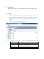
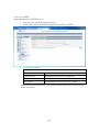
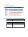
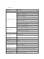
SWE-0216G3 User’s Manual Version : SWE-0216G3_Manual_V1 FCC Warning This device has been tested and found to comply with limits for a Class-A digital device, pursuant to Part 2 and 15 of FCC Rules. These limits are designed to provide reasonable protection against harmful interference when the equipment is operated in a commercial environment. This equipment generates and radiates radio frequency energy and, if not installed and used in accordance with the user’s manual, it may cause interference in which case users will be required to correct interference at their own expenses. CE Warning This is a Class-A product. In a domestic environment, this product may cause radio interference in which case the user may be required to take adequate measures. ii Contents 0. 1. 2. Introduction.................................................................................................................... 1 0.1. Package Contents ................................................................................................... 1 0.2. Features .................................................................................................................. 1 Installation ..................................................................................................................... 3 1.1. Setup to switch ....................................................................................................... 3 1.2. User Log in .............................................................................................................. 3 1.3. System Info ............................................................................................................. 5 Web Management .......................................................................................................... 6 2.1. System ..................................................................................................................... 6 2.1.1. System Management ...................................................................................... 6 2.1.2. IPv4 Setup ....................................................................................................... 7 2.1.3. IPv6 System settings ...................................................................................... 8 2.1.4. IPv6 Neighbor Setting .................................................................................... 9 2.1.5. IP Access List ................................................................................................. 10 2.1.6. Administration ............................................................................................... 11 2.1.7. User Interface ................................................................................................ 13 2.1.8. System Time .................................................................................................. 14 2.1.9. SSL Settings .................................................................................................. 16 2.1.10. DHCP Auto Configuration ........................................................................ 17 2.1.11. System Log Setting ................................................................................... 18 2.2. Physical Interface ................................................................................................. 19 2.3. Bridge .................................................................................................................... 21 2.3.1. Spanning Tree ............................................................................................... 21 2.3.2. Trunk Config.................................................................................................. 28 2.3.3. Mirroring........................................................................................................ 31 2.3.4. Loopback Detection ....................................................................................... 32 2.3.5. Static Unicast ................................................................................................ 33 2.3.6. Static Multicast ............................................................................................. 34 2.3.7. IGMP Snooping ............................................................................................. 35 2.3.8. Bandwidth Control ........................................................................................ 38 2.3.9. VLAN ............................................................................................................. 41 2.3.10. GVRP .......................................................................................................... 47 2.3.11. QoS ............................................................................................................. 50 2.4. SNMP .................................................................................................................... 55 iii 2.4.1. Engine ID ....................................................................................................... 55 2.4.2. View Table...................................................................................................... 56 2.4.3. Group Access Table ....................................................................................... 57 2.4.4. SNMP User/Group ........................................................................................ 58 2.4.5. Community Table .......................................................................................... 59 2.4.6. Trap Management ......................................................................................... 60 2.5. Access Control Config........................................................................................... 61 2.5.1. Policy Settings ............................................................................................... 61 2.5.2. Rate Control Settings.................................................................................... 65 2.5.3. Policy Database ............................................................................................. 66 2.6. RMON.................................................................................................................... 67 2.6.1. Global Settings .............................................................................................. 67 2.6.2. Statistics ........................................................................................................ 68 2.6.3. History ........................................................................................................... 69 2.6.4. Alarms ............................................................................................................ 70 2.6.5. Event .............................................................................................................. 71 2.7. Voice VLAN ........................................................................................................... 72 2.7.1. Voice VLAN Settings ..................................................................................... 72 2.7.2. Voice VLAN OUI Settings ............................................................................ 74 2.8. Security ................................................................................................................. 75 2.8.1. Port Access Control ....................................................................................... 75 2.8.2. Dial-in User ................................................................................................... 76 2.8.3. RADIUS ......................................................................................................... 77 2.8.4. TACACS+ ....................................................................................................... 78 2.8.5. Destination MAC Filter ................................................................................ 79 2.8.6. Denial of Service............................................................................................ 80 2.9. 2.10. Power Over Ethernet ........................................................................................... 81 DHCP Snooping ................................................................................................ 83 2.10.1. General Settings ........................................................................................ 83 2.10.2. VLAN Settings ........................................................................................... 84 2.10.3. Trusted Interfaces ..................................................................................... 85 2.10.4. Binding Database ...................................................................................... 86 2.11. LLDP.................................................................................................................. 87 2.11.1. LLDP Global Settings ............................................................................... 87 2.11.2. LLDP Neighbors information ................................................................... 89 2.12. Statistic Chart................................................................................................... 90 iv 2.12.1. Traffic Comparison .................................................................................... 90 2.12.2. Error Group................................................................................................ 91 2.13. Tool ..................................................................................................................... 92 2.13.1. Firmware Upgrade .................................................................................... 92 2.13.2. Config File Upload/Download ................................................................... 94 2.13.3. Cable Diagnostics ...................................................................................... 96 2.13.4. IEEE802.3az EEE ..................................................................................... 97 2.13.5. Reboot ......................................................................................................... 98 2.13.6. Ping ............................................................................................................. 99 2.14. Save Settings to Flash .................................................................................... 100 3. Specification ............................................................................................................... 101 4. Troubleshooting.......................................................................................................... 103 Cannot connect http://192.168.0.1 ........................................................................ 103 PoE PD is not working well. .................................................................................. 103 v 0. Introduction In this User Manual, it will not only tell you how to install and connect your network system but configure and monitor the SWE-0216G3 through the web by (RJ-45) serial interface and Ethernet ports step-by-step. Many explanations in detail of hardware and software functions are shown as well as the examples of the operation for web-based interface. 0.1. Package Contents Before you start to install this switch, please verify your package that contains the following items: Giga Ethernet Switch Power cord Safety Warranty Rack-mount Kit If any of these items is found missing or damaged, please contact your local supplier for replacement 0.2. Features All RJ-45 port support Power over Ethernet(up to 30.8W/port) Web Smart features provide better manageability, security, QoS, and performance 802.3az Energy Efficient Ethernet standard Dual speed SFPs for FE or Giga bit fiber uplink s-Flow supports Easy-Port-Configuration for ease of setup in the IP Phone, IP Camera or Wireless environment 1 Front Panel Reset Button click Reboot and Restore default configuration Power green off The switch is receiving AC input power and is operating normally. The switch is not receiving AC power PoE MAX red Over the maximum PoE power, the switch can deliver. off Not reach maximum PoE power total. RJ-45Port Link/Act green GbE connection is available, Flashing mean busy. amber FE or 10Mbps connection is available, Flashing mean busy. off No connection is available. PoE green PoE power is being supplied to the PD normally. amber Over the maximum PoE power, the switch can deliver. off No PoE power is supplied. SFP Port Link/Act green Gb connection is available, Flashing mean busy. amber 10/100 connection is available, Flashing mean busy. off No connection is available. Maximum PoE power, it can deliver is limited under 180W.It cat connect up to 5 IEEE802.3at Cat.4 PD devices or 12 IEEE802.3af Cat.0 PD devices. 2 1. Installation This chapter instructs you how to configure and manage the SWE-0216G3 through the web user interface. With this facility, you can easily access and monitor through any one port of the switch all the status of the switch, including MIBs status, each port activity, Spanning tree status, port aggregation status, multicast traffic, VLAN and priority status, even illegal access record and so on. 1.1. Setup to switch The switch performance is greatly affected where to install. When you install the switch, please consider the following points: Fairly cool and dry place. Free from noise(e.g. electromagnetic field generators, vibration, dust, heat, wet, or direct sunlight expositing) Make about 10cm space with rear side and top for heat spreading When you install switch to rack, free from another racking weight. When you install switch on a level surface, attach rubber feet to bottom of the switch. So rubber feet avoid case were scratched. When you connect switch, please connect the switch to outlet first. Seconds connect PC with LAN cable. 1.2. User Log in The default values of the SWE-0216G3is listed in the table below: IP Address 192.168.0.1 Subnet Mask 255.255.255.0 Default Gateway 192.168.0.254 Username admin Password admin After the SWE-0216G3 has been finished physical install, you can browse it. For instance, type http://192.168.0.1 in the address row in a browser, it will show the following screen and ask you inputting username and password in order to login and access authentication. The default username is “admin”, and password is “admin”. For the first time to use, please enter the default username and password, and then click the <Login> button. The login process now is completed. In this login menu, you 3 have to input the complete username and password respectively, the SWE-0216G3 will not give you a shortcut to username automatically. This looks inconvenient, but safer. NOTE: When you login the Switch WEB to manager. You must first type the Username of the admin. Password was blank, so when you type after the end Username, please press enter. Management page to enter WEB. When you login SWE-0216G3 series switch Web UI management, you can use both ipv4 login to manage To optimize the display effect, we recommend you use Microsoft IE 6.0 above, Netscape V7.1 above or FireFox V1.00 above and have the resolution 1024x768. The switch supported neutral web browser interface. NOTE: AS SWE-0216G3 the function enable DHCP, so If you do not have DHCP server to provide IP addresses to the switch, the Switch default IP 192.168.0.1 4 1.3. System Info After you login, the switch shows you the system information. This page is default and tells you the basic information of the system; you will know the software version used, MAC address, IPv4/v6 info and so on. This is helpful while malfunctioning. 5 2. Web Management In the first all settings were not saved before click “Save Setting to Flash” in the left side menu. If you setup any configuration before click “Save setting to Flash”, all configuration were destroy when reset the switch or power lost. 2.1. System 2.1.1. System Management This section explains how to assign a name, location, and contact information for the switch. This information helps in identifying each specific switch among other switches in the same local area network. Entering this information is optional. 1. Log into your switch management page. 2. Click System, and click on System management. 3. 5 setting is shown. System description [Fixed]Model name System Object ID [Fixed]SNMP MIB ID System Name [Variable]Switch name(0-16 letter) System location [Variable]Switch location(0-32letters) System Contact [Variable]Switch contact(0-32letters) Review the settings. When you have completed making changes, click Apply to save the settings. 6 2.1.2. IPv4 Setup This section explains how to setup switch IPv4 address. Mostly, IP address is change to your existing network to access management page from your network 1. Log into your switch management page. 2. Click System, and click on IPv4 Setup. 3. 5 setting is shown. System MAC Address [Fixed]switch MAC address System IP Address [Variable]Input IP each octet.( 4 octets) System Subnet mask [Variable]Input same subnet (4 octets) System Default Gateway [Variable]Gateway IP Address (4 octets) System IP Mode [Selection]DHCP/Static selection. Review the settings. When you have completed making changes, click Apply to save the settings NOTE: “DHCP” is selected in “System IP Mode”, Your switch IP is decided by DHCP server in same network. If no DHCP server is available, the switch IP address fixed “192.168.0.1” and IP Mode setting turn into “Static” . 7 2.1.3. IPv6 System settings This section explains how to setup IPv6 address. This IPv6 address is used for in-band connectivity only, not effect port address learning, switching, routing. 1. Log into your switch management page. 2. Click System, and click on IPv6 System Settings. 3. 8 setting is shown. IPv6 System Settings IPv6 State [Selection]Enabled / Disabled selection DHCPv6 Client [Selection] Enabled / Disabled selection IPv6 Unicast Address / [Variable]Input unicast IPv6 address and subnet Prefix Length mask with length after “/” IPv6 Static Gateway [Variable]Input gateway IPv6 address IPv6 Dynamic Gateway [Fixed].When IPv6 DHCP enable, Gateway address is shown from DHCPv6 configuration. NS Retransmit Time Settings NS Retransmit Time [Variable]Input cycle time of Neighbor Solicitation packet of ICMPv6 Link Local Address Settings Automatic Link Local [Selection]Enabled / Disabled selection Address 8 Link Local Address / Prefix [Variable]Input link local IPv6 address and subnet length mask with length after “/” Review the settings. When you have completed making changes, click Apply to save the settings 2.1.4. IPv6 Neighbor Setting This section explains how to setup IPv6 Neighbor setting. You could modify IPv6 supported neighboring devices. 1. Log into your switch management page. 2. Click System, and click on IPv6 Neighbor Settings 3. 2 setting is shown. IPv6 Neighbor Address Neighbor IPv6 Address [Variable]Input Neighbor IPv6 address. Link Layer MAC Address [Variable]Input MAC address, paired Neighbor IPv6 address Review the settings. When you have completed making changes, click Add to save the settings 4. IPv6 Neighbor Setting List is shown. You can search with IPv6 address, MAC address, or State. And you can delete IPv6 Neighbor entry directory. After search, each entry shows Delete button, and delete entry one by one. 9 2.1.5. IP Access List This section explains how to limit management page with IP address in white list way. 1. Log into your switch management page. 2. Click System, and click on IP Access List 3. 1 setting is shown. IP Access List IP Restriction Status [Selection]Enabled / Disabled selection Review the settings. When you have completed making changes, click Apply to save the settings 4. 1setting is shown IP address settings IP Address [Variable]Input accessible IP address.(max 10 entry) Review the settings. When you have completed making changes, click Apply to save the settings 5. Management page accessible IP List is shown. You can delete with entry with push Delete button, and delete all entries with pushing Delete all button. 10 2.1.6. Administration This section explains how to change the administrator password and create other administrative user accounts for access to the switch management page. NOTE: Index1 default admin user cannot be change user name and delete. 1. Log into your switch management page. 2. Click System, and click on Administration 3. 3 setting is shown. Administration Settings User Name [Variable]Input user name of additional account.(1-12 alphanumeric letter) Password [Variable]Input password of additional account.(1-12 alphanumeric letter) Confirm Password Input password again. Review the settings. When you have completed making changes, click Add to save the settings 11 4. Administration table is shown. You can delete additional user. And change another password. Review the settings. When you have completed making changes, click Apply to save the settings 12 2.1.7. User Interface This section explains how to enable SNMP on the switch and modify the switch management page idle timeout settings 1. Log into your switch management page. 2. Click System, and click on User Interface 3. 2 settings are shown. Status Settings SNMP Agent [Selection]Enabled / Disabled selection. Web Server Status [Fixed]Display current web management status Review the settings. When you have completed making changes, click Apply to save the settings 4. 2 settings are shown Timeout Settings Web Idle Timeout [Variable]Input auto logout time(3-60min) Group Interval [Variable]Input SNMP search interval(0:disable 120-1225sec) Review the settings. When you have completed making changes, click Apply to save the settings 13 2.1.8. System Time This section explains how to setup switch clock. It used for system logging. 1. Log into your switch management page. 2. Click System, and click on System Time 3. 14 settings are shown. Current Time Settings Clock Mode [Fixed]Current Clock mode is shown which of “Local Time” or “SNTP”. Current Time [Fixed]Date and Time are shown(Default 2009-01-01 00:00:00 + uptime shown) Time Zone [Fixed]If this switch is SNTP mode, Time zone that used for SNTP is shown. Date/Time Settings Clock Mode [Selection]Local Time / SNTP selection Local Time Settings (availed in Clock Mode: Local Time) Date settings [Variable]Input now date(year, month, day for each form) Time Settings [Variable]Input now time (hour, minute, seconds for each form) 14 Simple Network Time protocol(SNTP)Settings (availed in Clock Mode: SNTP) SNTP Primary Server [Variable]Input first source SNTP server IP address. SNTP Secondary Server [Variable]Input second source SNTP server IP address. SNTP Poll interval [Variable]Input interval time to synchronize time Time Zone [Selection] choose time zone where this switch is located. Additional Time parameters Daylight Saving Time [Selection]Enabled / Disabled selection Status From [Selection]Select date of starting DST To [Selection]Select date of ending DST DST Offset [Selection]30min / 1hr selection offset length Review the settings. When you have completed making changes, click Apply to save the settings 15 2.1.9. SSL Settings This section explains how to setup access management page on SSL connection. You could access switch secure 1. Log into your switch management page. 2. Click System, and click on IPv6 Neighbor Settings 3. 1 setting is shown. SSL Settings SSL Status [Selection]Enabled / Disabled selection Review the settings. When you have completed making changes, click Apply to save the settings NOTE: When turn on SSL Status, You cannot access ttp://192.168.0.1 (switch IP), but you can access https://192.168.0.1 instead of previous address . 16 2.1.10. DHCP Auto Configuration This section explains how to configuration function via DHCP. You can update Config file via DHCP 1. Log into your switch management page. 2. Click System, and click on DHCP Auto Configuration 3. 1 setting is shown. DHCP Auto Configuration Auto Configuration Mode [Selection]Enabled / Disabled selection Review the settings. When you have completed making changes, click Apply to save the settings NOTE: You can make configuration file at TOOL>Config File Upload/Download>via HTTP or via TFTP. And put Config file as BOOT file in TFTP server. 17 2.1.11. System Log Setting This section explains how to configuration function via DHCP. You can update Config file via DHCP 1. Log into your switch management page. 2. Click System, and click on System Log Setting 3. 6 settings are shown. System Log Setting Time Stamp [Selection]Enabled / Disabled selection Message Bufferd Size [Variable]Input how many line logs saved in switch. (1-50) Syslog Status [Selection]Enabled / Disabled selection Syslog Server IP [Variable]Input syslog server IP address. Facility [Selection]Select syslog server facility # . (You can help logging separate another device). Logging Level [Selection]Alert/Critical/Warning/Info selection. (message increase Alert<Critical<Warning<Info) Review the settings. When you have completed making changes, click Apply to save the settings 18 2.2. Physical Interface This section explains how to configure interface settings. 1. Log into your switch management page. 2. Click Physical Interface. 3. Each port 10 settings are shown. Physical Interface table Port [Fixed]Port Number in combo port: (1) copper cable (2)100Mbps SFP module (3)1Gbps SFP module Trunk [Fixed]Trunk ID Number Type [Fixed]Supported Connection Type Link Status [Fixed]Link Online / Offline Status. Admin.Status [Selection]Enabled / Disabled selection for block forwarding. Mode [Selection]Auto / 1000/Full / 100/Full / 10/Full / 100/Half / 10/Half selection. in combo port: (2)100/Full only (3)Auto / 1000/Full Jumbo [Selection]Enabled / Disabled selection for Jumbo packet communication. 19 Flow Ctrl [Selection] Enabled / Disabled selection for switch using pause packet for flow control EAP [Selection] Enabled / Disabled selection for switch allow EAP packet pass-through BPDU [Selection] Enabled / Disabled selection for switch allow BPDU packet pass-through Review the settings. When you have completed making changes, click Apply to save the settings 20 2.3. Bridge This section explains how to make network 2.3.1. Spanning Tree This section explains how to setup spanning tree. Spanning tree protocol technology help you make network, less loop, more flexible. 2.3.1.1. Protocol Settings This section explains how to setup protocol parameter. 1. Log into your switch management page. 2. Click Bridge, clicks Spanning Tree, and Click on Protocol Setting. 3. 13 settings are shown. Spanning Tree Protocol Settings Global STP Status [Selection]Enabled / Disabled selection Protocol Version [Selection]STP / RSTP / MSTP selection STP:IEEE802.1d RSTP:IEEE802.1w MSTP:IEEE802.1s Bridge Priority [Selection]Select 0-61440 priority 0 : root bridge 32768;default Maximum Age [Variable]Input waiting time for non-BPDU packet coming(6-40) 21 Hello Time [Variable]Input cycle time for submitting BPDU packet when the switch is root bridge.(1-10) Forward Delay [Variable]Input wait time for learning and listening MAC address.(4-30) Transmit Hold Count [Variable]Input how many BPDU packet send from switch per second(1-10) Max Hop Count [Variable]Input how many hop BPDU packet from root bridge(6-40) Root Information Root Bridge [Fixed]root bridge ID shown Root Cost [Fixed]cost for root bridge path shown Root Maximum Age [Fixed]root bridge settings shown Root Forward Delay [Fixed]root bridge settings shown Root Port [Fixed]port to root bridge shown Review the settings. When you have completed making changes, click Apply to save the settings 22 2.3.1.2. Port Setting This section explains how to setup STP Port parameter. 1. Log into your switch management page. 2. Click Bridge, clicks Spanning Tree, and Click on Port Setting. 3. 10 settings are shown. Port Settings Port [Fixed]port number shown STP Status [Selection] Enabled / Disabled selection Enable : effect from BPDU packet Disable : passthrough BPDU packet Priority [Selection]Select priority in the case of same cost path are exists.(0-240, upper port selecting) Admin Cost [Variable]Input path cost if you need setting path cost expressly(0-200000000) External Cost [Fixed]Path Cost shown 100Mbps : 200000 1Gbps : 20000 State [Fixed]STP tree state shown Blocking / Listening / Forwarding /Disable Edge [Selection]Select Force True / Force False / Auto Force True: non-bridge node connected Force False: bridge node connected 23 P2P [Selection] Select Force True / Force False / Auto Force True: full-duplex rapidly entering forwarding state. Force False: half-duplex operation or non-edge port use Restricted Role [Selection]Select True / False True : non connected root network False: maybe connected root network Restricted TCN [Selection]Select True / False True: DON’T affect Topology Change Notification. False : affect Topology Change Notification If you want change port accept RSTP or STP BPDU configuration, Click Migrate Review the settings. When you have completed making changes, click Apply to save the settings 24 2.3.1.3. MST Setting This section explains how to setup MSTP parameter. 1. Log into your switch management page. 2. Click Bridge, clicks Spanning Tree, and Click on MST Settings. 3. 2 settings are shown. MST Configuration Identification Setting Configuration Name [Variable]Input unique name for Multiple Spanning Tree Instance. Default value setup MAC address Revision Level [Variable]Input same MSTP region value. Review the settings. When you have completed making changes, click Apply to save the settings 4. 3 settings are shown MST Instance Settings MSTI ID [Variable]Input MSTI ID associated with VID List. VID List [Variable]Input VID List Priority [Selection]Select bridge priority low number is hi priority Review the settings. When you have completed making changes, click Add to save the settings 5. MST Table is shown If change any parameter, click Apply. Delete entry, click Delete. 25 2.3.1.4. Instance Information This section explains how to check MSTI. 1. Log into your switch management page. 2. Click Bridge, clicks Spanning Tree, and Click on Instance Information. 3. Current MSTI information table is shown. 26 2.3.1.5. MST Port Setting This section explains how to check MSTI. 1. Log into your switch management page. 2. Click Bridge, clicks Spanning Tree, and Click on MST Port Settings 3. Current MSTI information table is shown. 27 2.3.2. Trunk Config Trunking technology give you make redundancy and high speed network. 2.3.2.1. Trunking This section explains how to setup Trunking group. You can make up to 8 group trunk path make in this switch 1. Log into your switch management page. 2. Click Bridge, clicks Trunking Setting, and Click on Trunking. 3. 3 settings are shown Trunking Settings Trunk ID [Fixed] List up 1-8 trunk group id. Port List1-16 [Check Box]Check same trunk group port State [Selection]Select Active / Passive / Manual / Disable. Review the settings. When you have completed making changes, click Add to save the settings 28 2.3.2.2. LACP Group Status This section explains how to check Trunking group 1. Log into your switch management page. 2. Click Bridge, clicks Trunking Setting, and Click on LACP Group Status. Review current status. 29 2.3.2.3. Port Priority This section explains how to setup Trunking group. You can make up to 8 group trunk path make in this switch 1. Log into your switch management page. 2. Click Bridge, clicks Trunking Setting, and Click on Port Priority In same Trunk Group and same priority, lower port is used. 3. Review the settings. When you have completed making changes, click Add to save the settings 30 2.3.3. Mirroring This section explains how to setup Mirroring. It’s used for duplicate or capture packet. 1. Log into your switch management page. 2. Click Bridge, and clicks mirroring. 3. 4 settings are shown Mirroring Settings Status [Selection]Enabled / Disabled selection Mirror Target Port [Selection]Select output duplicated packet port Mirroring Port Settings Ingress Port [Check Box]Check duplicates Rx packet Port. Egress Port [Check Box]Check duplicates Tx packet Port. Review the settings. When you have completed making changes, click Apply to save the settings 31 2.3.4. Loopback Detection This section explains how to setup Loopback discover and block function. It makes avoid confuse network. 1. Log into your switch management page. 2. Click Bridge, and click Loopback Detection. 3. 6 settings are shown Loopback Detection Settings Status [Selection]Enabled / Disabled selection Loopback Detection Global Settings Interval [Variable]Input cycle time for sending detection packet Recover Time [Variable]Input cycle time for recover blocking port Loopback Detection Table Port [Fixed]All/1-16 ports are listed up. Loopback Detection State [Selection]Enabled / Disabled selection Loop Status [Check Box]Check duplicates Tx packet Port. Review the settings. When you have completed making changes, click Apply to save the settings 32 2.3.5. Static Unicast This section explains how to setup Static Unicast. You can make specific MAC address packet to forward specific port. 1. Log into your switch management page. 2. Click Bridge, and click Static Unicast. 3. 3 settings are shown Static Unicast Address Settings 802.1Q VLAN [Variable]Input VLAN ID of source MAC address packet coming. Default, all port belongs with VLAN ID 0. MAC Address [Variable]Input source MAC address Port Member Settings [Selection]Select destination Port. Review the settings. When you have completed making changes, click Apply to save the settings 4. 802.1Q VLAN Table is shown If change destination port, click Modify. If delete entry, click Delete. 33 2.3.6. Static Multicast This section explains how to setup Static Multicast. You can make specific MAC address packet to forward specific multi ports. 1. Log into your switch management page. 2. Click Bridge, and click Static Multicast. 3. 3 settings are shown Static Multicast Address Settings 802.1Q VLAN [Variable]Input VLAN ID of source MAC address packet coming. Default, all port belongs with VLAN ID 0. MAC Address [Variable]Input source MAC address Port Member Settings [Check Box]Check destination Port. All : Check all ports Review the settings. When you have completed making changes, click Apply to save the settings 4. 802.1Q VLAN Table is shown If change destination port, click Modify. If delete entry, click Delete. 34 2.3.7. IGMP Snooping IGMP function helps efficiently IPv4 Multicast Network. 2.3.7.1. IGMP Snooping Settings This section explains how to setup IGMP Snooping. You can make IGMP snoop and IGMP Query setting. 1. Log into your switch management page. 2. Click Bridge, clicks IGMP Snooping, and click IGMP Snooping Settings. 3. 8 settings are shown IGMP Snooping Settings Status [Selection]Enabled / Disabled selection. Age-Out Timer [Variable]Input waiting time after no dynamic MAC address exists.(130-153025) Querier Status [Selection] Enabled / Disabled selection. Query Interval [Variable]Input cycle time of sending IGMP query(60-600) Max Response Time [Variable]Input waiting time after member don’t response query Robustness Variable [Variable]Input avoidance how ignore packet loss. Last Member Query [Variable]Input time to high-speed secession Interval Router Timeout [Variable]Input time to leave after multicast router has no multicast group 35 Review the settings. When you have completed making changes, click Apply to save the settings 4. 802.1Q VLAN Table is shown You can check Multicast group by VLAN ID. 36 2.3.7.2. IGMP Snooping Router Port This section explains how to check multicast router port and modify static router port. 1. Log into your switch management page. 2. Click Bridge, clicks IGMP Snooping, and click IGMP Snooping Router Port. 3. 802.1Q VLAN Table is shown If you want to change static multicast router port, click Modify. 37 2.3.8. Bandwidth Control Bandwidth control helps you limit pps base packet control for DLS, Broadcast, and Multicast. The other way, limit kbps base stream control for Tx & Rx. 2.3.8.1. Storm Control This section explains how to setup Storm Control. This function helps you from network down by packet non- involuntarily stream 1. Log into your switch management page. 2. Click Bridge, clicks Bandwidth Control, and click Storm Control. 3. 5 settings are shown Storm Control Settings Port [Fixed]Port number is listed up. DLF [Selection] Enabled / Disabled filtering selection. (Destination Lookup Failure) Broadcast [Selection] Enabled / Disabled filtering selection. Multicast [Selection] Enabled / Disabled filtering selection. Threshold [Variable]Input limit late with multiple 64pps(packet per second) Review the settings. When you have completed making changes, click Apply to save the settings 38 2.3.8.2. Ingress Rate Limiting This section explains how to setup Ingress rate Limiting. You can setup port Incoming flow control each port. 1. Log into your switch management page. 2. Click Bridge, clicks Bandwidth Control, and click Ingress Rate Limiting. 3. 3 settings are shown Storm Control Settings Port [Fixed]Port number is listed up. Bandwidth [Variable]Input limit late with multiple 64kbps. Status [Selection] Enabled / Disabled selection. Review the settings. When you have completed making changes, click Apply to save the settings 39 2.3.8.3. Egress Rate Limiting This section explains how to Ingress rate Limiting. You can setup port Outgoing flow control each port 1. Log into your switch management page. 2. Click Bridge, clicks Bandwidth Control, and click Egress Rate Limiting. 3. 3 settings are shown Storm Control Settings Port [Fixed]Port number is listed up. Bandwidth [Variable]Input limit late with multiple 64kbps. Status [Selection] Enabled / Disabled selection. Review the settings. When you have completed making changes, click Apply to save the settings 40 2.3.9. VLAN VLAN is used to make separated network in one switch. 2.3.9.1. Tagged VLAN This section explains how to setup VLAN by tagging 1. Log into your switch management page. 2. Click Bridge, clicks VLAN, and click Tagged VLAN. 3. 6 settings are shown Tagged VLAN Settings VLAN ID [Variable]Input VLAN ID.(2-4094) VLAN Name [Variable]Input VLAN nickname.(0-32letter) Management VLAN [Selection] Enabled / Disabled selection. If you select Enable, you can access management page from this VLAN. Static Tagged [Selection]Select port for add-tag when outgoing. Static Untagged [Selection]Select port for no add-tag when outgoing. Not Member [Selection]Select port for not VLAN member. Review the settings. When you have completed making changes, click Apply to save the settings 4. Current VLAN table is shown. 41 2.3.9.2. Port Settings This section explains how to setup Port Setting of acceptable incoming frame type. 1. Log into your switch management page. 2. Click Bridge, clicks VLAN, and click Port Setting. 3. 4 settings are shown Port Settings Port [Fixed]Port number is listed up. PVID [Variable]Input Port VLAN ID. Acceptable Frame Types [Selection] All / Tagged / Untagged and Priority Tagged selection. Ingress Filtering [Selection]Enabled / Disabled selection Review the settings. When you have completed making changes, click Apply to save the settings 42 2.3.9.3. Forwarding Table Mode This section explains how to change MAC address learning mode. 1. Log into your switch management page. 2. Click Bridge, clicks VLAN, and click Forwarding Table Mode. 3. 1 setting is shown Forwarding Table Mode Learning Mode [Selection]IVL / SVL selection. IVL : Independent VLAN Learning MAC address table exist each VLAN. It is selected edge device connected. SVL : Sheared VLAN Learning MAC address table exist whole switch. It is selected cross over multi VLAN network. Review the settings. When you have completed making changes, click Apply to save the settings 43 2.3.9.4. Dynamic Forwarding Table This section explains how to check current VLAN table. 1. Log into your switch management page. 2. Click Bridge, clicks VLAN, and click Dynamic Forwarding table. 3. 7 settings are shown Dynamic Forwarding Table Setting Port [Selection] All / 1-16 selection. When you select one, Current Forwarding table is filtered. Dynamic Forwarding Table ID [Fixed]Entry ID is shown VID [Fixed]VLAN ID is shown Port [Fixed]Port number is shown MAC Address [Fixed]Shows MAC address. Type [Fixed]Dynamic / Static is shown. VLAN Mode [Fixed]Shows VLAN type. Review the settings. 44 2.3.9.5. Private VLAN This section explains how to Private VLAN. It is used as known as Port-based VLAN. 1. Log into your switch management page. 2. Click Bridge, clicks VLAN, and click Private VLAN. 3. 3 setting are shown Private VLAN Settings State [Selection]Enabled / Disabled selection Port Select Source Port [Selection]Packet incoming port. Forwarding Ports [Check Box]Packet outgoing port Review the settings. When you have completed making changes, click Apply to save the settings 45 2.3.9.6. VLAN Current Database This section explains how to check VLAN Current Database. 1. Log into your switch management page. 2. Click Bridge, clicks VLAN, and click VLAN Current Database. 3. 3 setting are shown 802.1Q Tagged VLAN VLAN ID [Fixed]Shows VLAN ID VLAN Name [Fixed]Shows VLAN nickname VLAN FDB ID [Fixed]Shows VLAN Forwarding Database ID Member Ports [Fixed]Shows VLAN member port Untagged Ports [Fixed]Shows VLAN untagged port. Status [Fixed]Shows status. Review the settings 46 2.3.10. GVRP GVRP technology is share VLAN information and configure automatically. 2.3.10.1. GVRP Global Settings This section explains how to setup GVRP. 1. Log into your switch management page. 2. Click Bridge, clicks GVRP, and click GVRP Global Settings. 3. 1 setting is shown GVRP Global Settings GVRP Status [Selection]Enabled / Disabled selection Review the settings. When you have completed making changes, click Apply to save the settings 47 2.3.10.2. Port Settings This section explains how to setup GVRP port Settings. 1. Log into your switch management page. 2. Click Bridge, clicks GVRP, and click Port Settings. 3. 1 setting is shown GVRP Port Settings Port [Fixed]All / 1-16 selection Dynamic Vlan Status [Selection]Enabled / Disabled GVRP selection Restricted VLAN [Selection]Enabled / Disabled following GVRP Registration configuration selection Review the settings. When you have completed making changes, click Apply to save the settings 2.3.10.3. Time Settings This section explains how to setup cycle Join/Leave. 1. Log into your switch management page. 2. Click Bridge, clicks GVRP, and click Time Settings. 48 3. 1 setting is shown Time Settings Port [Fixed]All / 1-16 selection Join Time [Variable]Input cycle time to PDU packet. Leave Time [Variable]Input waiting time for restore non GARP state. Leave All Time [Variable]Input cycle time for checking all port in VLAN Review the settings. When you have completed making changes, click Apply to save the settings 49 2.3.11. QoS QoS technology help you shape traffic or reorder connection timing. 2.3.11.1. CoS This section explains how to Class of Service. 1. Log into your switch management page. 2. Click Bridge, clicks QoS, and click CoS. 3. 2 settings are shown CoS QoS Status [Selection]Enabled / Disabled selection Traffic Class [Fixed]Current look up Traffic Class. QoS Table CoS Value [Fixed]0~7 CoS category is listed up Priority Value [Selection]Low / Medium / High / Highest Review the settings. When you have completed making changes, click Apply to save the settings 50 2.3.11.2. Port Priority This section explains how to setup port base priority. 1. Log into your switch management page. 2. Click Bridge, clicks QoS, and click Port Priority. 3. 2 settings are shown Port Priority Port [Fixed]All /1-16 port are listed up User Priority [Selection]0-7 priority selection. Review the settings. When you have completed making changes, click Apply to save the settings 51 2.3.11.3. DSCP This section explains how to setup Differentiated Services Code Point-base traffic settings. 1. Log into your switch management page. 2. Click Bridge, clicks QoS, and click Port DSCP. 3. 2 settings are shown DSCP Class Mapping Settings DSCP in [Fixed]0-63 all DSCP pattern are listed up. Queue [Selection] Low / Medium / High / Highest Review the settings. When you have completed making changes, click Apply to save the settings 52 2.3.11.4. Scheduling Algorithm This section explains how to setup packet Scheduling Algorithm. 1. Log into your switch management page. 2. Click Bridge, clicks QoS, and click Scheduling Algorithm. 3. 1 setting is shown Schedule Algorithm Settings Scheduling Algorithm [Selection]Strict Priority/Weighted Round Robin selection. Strict Priority : Until upper priority packet send all out, No lower priority packet going out. Weight Round Robin : each packet has chance of sending each term. In one term,The number of times to send packet is setup following ratio based on a priority Review the settings. When you have completed making changes, click Apply to save the settings 53 2.3.11.5. IPv6 Traffic Class Priority This section explains how to setup Traffic Class Priority of IPv6. 1. Log into your switch management page. 2. Click Bridge, clicks QoS, and click IPv6 Traffic Class Priority. 3. 3 settings are shown IPv6 Traffic Class Priority Settings State [Selection]Enabled / Disabled selection. IPv6 Traffic Class Settings IPv6 Traffic Class [Variable]Input IPv6 traffic class(0-255) Class ID [Selection] Low / Medium / High / Highest Review the settings. When you have completed making changes, click Apply to save the settings 4. IPv6 Traffic Class Table is shown. Review the settings. You can delete with entry with push Delete button. 54 2.4. SNMP SNMP technology is help you sense an obstacle 2.4.1. Engine ID This section explain how to change engine ID 1. Log into your switch management page. 2. Click SNMP, and click Engine ID. 3. 1 setting is shown Engine ID Setting Engine ID [Variable]Switch Unique Name divide another switch. Review the settings. When you have completed making changes, click Apply to save the settings 55 2.4.2. View Table This section explains how to specific MIB access optimizes and limitation. 1. Log into your switch management page. 2. Click SNMP, and click Engine ID. 3. 4 settings are shown SNMP View Table View Name [Variable]Switch Unique Name divide another switch. Subtree OID [Variable]Input OID of you want to add OID Mask [Variable]Input OID Mask of limitation of public View Type [Selection] included/excluded selection. Review the settings. When you have completed making changes, click Apply to save the settings 4. SNMP View table is shown Review the settings. You can delete with entry with push Delete button. 56 2.4.3. Group Access Table This section explains how to specific MIB access policy. 1. Log into your switch management page. 2. Click SNMP, and click Group Access table. 3. 6 settings are shown SNMP Group Access Settings Group Name [Variable]Input Group of MIB access. Read View [Variable]Input object name of view acceptable Write View [Variable] Input object name of write acceptable Notify View [Variable] Input object name of trap acceptable Security Model [Selection]v1/v2c/v3 selection, Security Level(v3 only) [Selection]NoAuthNoPriv/AuthNoPriv/AuthPriv selection NoAuth : no password access NoPriv: no encrypted access Review the settings. When you have completed making changes, click Apply to save the settings 4. SNMP Group Access Table is shown. Review the settings. You can delete with entry with push Delete button 57 2.4.4. SNMP User/Group This section explains how to specific MIB access users and groups. 1. Log into your switch management page. 2. Click SNMP, and click SNMP User/Group. 3. 5 settings are shown SNMP User / Group Settings User Name [Variable]Input add username. Group Name [Variable]Input group of add or belong user SNMP Version [Selection]v1 / v2c / v3 selection Encryption(v3) [Check Box]enable encrypt and auth method Auth Protocol(encrypted) [Variable] MD5/SHA1 selection Password [Variable] Input password for authentication Priv Protocol(encrypted) [SelectionInput password for encrypt Password(DES) [Variable] Input password Review the settings. When you have completed making changes, click Apply to save the settings 4. SNMP User /Group Table is shown. Review the settings. You can delete with entry with push Delete button 58 2.4.5. Community Table This section explains how to specific MIB access Community Table. 1. Log into your switch management page. 2. Click SNMP, and click Community Table. 3. 2 settings are shown SNMP Community Settings Community Name [Variable]Input new Community Name User Name(View Policy) [Variable]Input username in use as View Policy Review the settings. When you have completed making changes, click Apply to save the settings 4. SNMP View Table is shown. Review the settings. You can delete with entry with push Delete button 59 2.4.6. Trap Management This section explains how to specific trap host setting. 1. Log into your switch management page. 2. Click SNMP, and click Community Table. 3. 1 setting is shown SNMP Community Settings State [Selection]Enabled/Disabled selection Review the settings. When you have completed making changes, click Apply to save the settings 4. 3 settings are shown Add Host Table Host IP Address [Selection]Enabled/Disabled selection SNMP Version [Selection]v1 / v2c / v3-NoAuthNoPriv / v3-NoAuthPriv / v3-AuthPriv selection. Community Name / Input Community name or User name for trap user User Name belongs. Review the settings. When you have completed making changes, click Apply to save the settings 5. Trap Management Table is shown. Review the settings. You can delete with entry with push Delete button 60 2.5. Access Control Config Access Control is help you different way traffic filtering or shaping 2.5.1. Policy Settings This section explains you how to add filtering entry. 1. Log into your switch management page. 2. Click Access Control Config, and click Policy Settings. 3. Add new policy 1. Push AddL2+IPv4 61 23 settings are shown Add L2+IPv4 Policy Index [Variable]Input index number. Source MAC Address [Variable]Input Source MAC address. Mask Length [Variable]Input Source MAC mask address Destination MAC Address [Variable]Input Destination MAC address. Mask Length [Variable]Input Destination MAC mask address VLAN ID [Variable]Input source VLAN ID 802.1p Priority [Variable]Input 0-7 number. Ether Type [Variable]Input Ether Type in hex digit Protocol [Variable]Input protocol(e.g. IP is 5) IPv4 Source IP Address [Variable]Input source IP address Mask Length [Variable]Input source mask address IPv4 Destination IP [Variable]Input destination IP address Address Mask Length [Variable]Input destination mask address DSCP [Variable]Input DSCP number. Source L4 Port [Variable]Input source port number. Destination L4 Port [Variable]Input destination port number. Policy Sequence [Variable]Input process order Policy Action [Selection]Permit/Deny selection Replaced-CoS [Variable]Input CoS Value Replaced-DSCP [Variable]Input DSCP Value Rate Control [Variable]Input number of Rate Control entry Port List [Variable]Input port number which filter applied Review the settings. When you have completed making changes, click Add to save the settings 62 2. Push IPv6 16 settings are shown Add IPv6 Policy Index [Variable]Input index number. VLAN ID [Variable]Input source VLAN ID 802.1p Priority [Variable]Input 0-7 number. Protocol [Variable]Input protocol(e.g. IP is 5) IPv6 Source IP Address [Variable]Input source IP address Mask Length [Variable]Input source mask address IPv6 Destination IP [Variable]Input destination IP address Address Mask Length [Variable]Input destination mask address IPv6 Traffic Class [Variable]Input IPv6 traffic class number. Source L4 Port [Variable]Input source port number. Destination L4 Port [Variable]Input destination port number. Policy Sequence [Variable]Input process order Policy Action [Selection]Permit/Deny selection Replaced-CoS [Variable]Input CoS Value Rate Control [Variable]Input number of Rate Control entry Port List [Variable]Input port number which filter applied Review the settings. When you have completed making changes, click Add to save the settings 63 4. Policy Table is shown Review the settings. If you want to delete or modify entry, push Delete or Modify button. 64 2.5.2. Rate Control Settings This section explains how to add rate limit policy. This policy is used in Policy Settings. 1. Log into your switch management page. 2. Click Access Control Config, and click Rate Control settings. 3. 2 setting are shown Rate Control Settings Index [Variable]Input index number Committed Rate [Variable]Input committed speed rate with multiple 64kbps. Review the settings. When you have completed making changes, click Add to save the settings 4. Rate Control List is shown Review the settings. If you want to delete or change entry, push Delete or Apply button. 65 2.5.3. Policy Database This section explains how to check filter policy for each port 1. Log into your switch management page. 2. Click Access Control Config, and click Policy Database. 3. 2 settings are shown Policy Database Select Port [Selection]Any / 1-16 port selection Sort By [Selection]List up Index / Sequence order selection 4. Policy Table is shown If you want to check more detail, push Detail button. 66 2.6. RMON RMON technology help you Remote Network Monitoring about link path. 2.6.1. Global Settings This section explains how to enable RMON. 1. Log into your switch management page. 2. Click RMON, and click Global Settings. 3. 1 setting is shown Policy Database Select RMON Status [Selection]Enabled / Disabled selection Review the settings. When you have completed making changes, click Apply to save the settings 67 2.6.2. Statistics This section explains how to add track point for each port 1. Log into your switch management page. 2. Click RMON, and click Statistics. 3. 3 settings are shown Ethernet Statistics Settings Index [Variable]Input track entry number Port [Variable] Input one port number.(1-16) Owner [Variable]Input entry nickname. Review the settings. When you have completed making changes, click Add to save the settings 4. Ethernet Statistics Table is shown. If you want to delete entry, push Delete button on each entry. 68 2.6.3. History This section explains how to configure logging parameter. 1. Log into your switch management page. 2. Click RMON, and click History. 3. 5 settings are shown History Control Table Index [Variable]Input entry number Port [Variable]Input one port number.(1-16) Buckets Requested [Variable]Input number of revision history. Interval [Variable]Input cycle time for logging Owner [Variable]Input entry nickname. Review the settings. When you have completed making changes, click Add to save the settings 4. History Control Table is shown. If you want to delete entry, push Delete button on each entry. 69 2.6.4. Alarms This section explains how to configure Alarm threshold 1. Log into your switch management page. 2. Click RMON, and click Alarms. 3. 9 settings are shown RMON Alarm Table Index [Variable]Input entry number Interval [Variable]Input cycle time for logging Variable [Variable]Input variable of RMON MIB object Sample type [Selection]Absolute / Delta Value Absolute : check current value. Delta : check between amount of change from last interval sampling Rising threshold [Variable]Input value as upper level. Falling threshold [Variable]Input value as lower level. Rising Event Index [Variable]Input index number of Event(2.6.5) Falling Event Index [Variable]Input index number of Event(2.6.5) Owner [Variable]Input entry nickname. Review the settings. When you have completed making changes, click Add to save the settings 4. History Control Table is shown. If you want to delete entry, push Delete button on each entry. 70 2.6.5. Event This section explains how to configure fire event. 1. Log into your switch management page. 2. Click RMON, and click Alarms. 3. 5 settings are shown RMON Event Table Index [Variable]Input check entry number Description [Variable]Input timer nickname Type [Selection]None / Log /SNMP Trap / Log and Trap selection. Community [Variable]Input community for describe trap Owner [Variable]Input entry nickname. Review the settings. When you have completed making changes, click Add to save the settings 4. History Control Table is shown. If you want to delete entry, push Delete button on each entry. 71 2.7. Voice VLAN Voice VLAN functions help you optimize IP Phone network. It works by using IP phone MAC address, and make Voice VLAN network, change CoS, and add VLAN dynamically. 2.7.1. Voice VLAN Settings This section explains how to configure Voice VLAN Setting 1. Log into your switch management page. 2. Click Voice VLAN, and click Voice VLAN Setting. 3. 4 settings are shown Voice VLAN Status Voice VLAN [Selection]Enabled / Disabled selection Voice VLAN Global Settings VLAN ID [Selection]Select Voice VLAN ID Aging Time [Variable]Input cycle time for IP Phone MAC table rebuild. CoS [Selection]Select 0-7 CoS value. Review the settings. When you have completed making changes, click Apply to save the settings 4. Voice VLAN Table is shown. Voice VLAN table Port [Fixed]All / 1-16 port are listed up 72 Auto Detection [Selection]Select Enabled / Disabled Status [Fixed]Static / None / Dynamic shown. If you want to modify entry, push Apply button on each entry. 73 2.7.2. Voice VLAN OUI Settings This section explains how to add MAC list 1. Log into your switch management page. 2. Click Voice VLAN, and click Voice VLAN OUI Setting. 3. 2 settings are shown Voice VLAN OUI Settings Description [Variable]Input entry Nickname. Telephony OUI [Variable]Input whole of MAC address. But you use same manufacture IP Phone, It is not necessary to input MAC address after the second unit. Review the settings. When you have completed making changes, click Add to save the settings 4. Voice VLAN Table is shown. If you want to delete entry, push Delete button on each entry. 74 2.8. Security This section explains you how to Port-base security 2.8.1. Port Access Control This section explains how to configure IEEE802.1X 1. Log into your switch management page. 2. Click Security, and click Port Access Control. 3. 3 settings are shown Port Access Control Settings NAS ID [Variable]Input name used for 802.1x identifier. Port Access Control [Selection]Enabled / Disabled selection Authentication Method [Selection]Local(Dial-in) / RADIUS / TACACS+ selection. Review the settings. When you have completed making changes, click Apply to save the settings 75 2.8.2. Dial-in User This section explains how to setup ID/PASSWORD authentication. It helps you authenticate system without external server. 1. Log into your switch management page. 2. Click Security, and click Dial-in User. 3. 3 settings are shown Dial-in User Settings User Name [Variable]Input user name Password [Variable]Input user password Dynamic VLAN [Variable]Input VLAN ID after login Review the settings. When you have completed making changes, click Apply to save the settings 4. Dial-in User Table is shown. If change password or VLAN, click Modify. If delete entry, click Delete. 76 2.8.3. RADIUS This section explains how to setup RADIUS authentication. You need external authenticate server. 1. Log into your switch management page. 2. Click Security, and click RADIUS. 3. 5 settings are shown RADIUS Settings Server Priority [Selection]1-5 priority selection Server IP Address [Variable]Input server IP address Server Port [Variable]Input port number of RADIUS server Accounting Port [Variable]Input port number of Accounting Shared Secret [Variable]Input secret key Review the settings. When you have completed making changes, click Apply to save the settings 4. RADIUS Table is shown. If you change IP address and so on, click Modify. If delete entry, click Delete. 77 2.8.4. TACACS+ This section explains how to setup TACACS+ authentication. You need external authenticate server. 1. Log into your switch management page. 2. Click Security, and click TACACS+. 3. 5 settings are shown TACACS+ Settings Server Priority [Selection]1-5 priority selection Server IP Address [Variable]Input server IP address Server Port [Variable]Input port number of RADIUS server Timeout [Variable]Input wait time for timeout Shared Secret [Variable]Input secret key Review the settings. When you have completed making changes, click Apply to save the settings 4. TACACS+ Table is shown. If you change IP address and so on, click Modify. If delete entry, click Delete. 78 2.8.5. Destination MAC Filter This section explains how to setup prohibition connection MAC address. You can make drop in-house server connection via GUEST user switch. 1. Log into your switch management page. 2. Click Security, and click Destination MAC Filter. 3. 1 setting is shown Add Destination MAC Filter MAC Address [Variable]Input prohibited connection MAC address. Review the settings. When you have completed making changes, click Add to save the settings 4. Destination MAC Table is shown. Review the settings. If you want to delete entry, click Delete. 79 2.8.6. Denial of Service This section explains you how to avoid Denial of Service attack. You can block doubtful communication at edge. 1. Log into your switch management page. 2. Click Security, and click Denial of Service. 3. 8 settings are shown DoS Setting TCP SYN packet with data [Selection]Allow / Deny selection. TCP Null Scan TCP flag bits [Selection]Allow / Deny selection. are zero TCP over [Selection]Allow / Deny selection. with [Selection]Allow / Deny selection. Multicast/Broadcast TCP Flags FIN-URG-PSH TCP Flags with SYN-RST [Selection]Allow / Deny selection. TCP/UDP port is zero [Selection]Allow / Deny selection. Fragmented ICMP v4 [Selection]Allow / Deny selection. ARP MAC SA Mismatch [Selection]Allow / Deny selection. (Src-MAC and Sender MAC of ARP Payload) Review the settings. When you have completed making changes, click Apply to save the settings 80 2.9. Power Over Ethernet This section explains you how to check PoE Current Status. 1. Log into your switch management page. 2. Click power Over Ethernet. 3. 10 settings are shown Power Over Ethernet Settings Power Budget [Fixed]Maximum Power supply Power Consumption [Fixed]Current Power supply Power Over Ethernet table Port [Fixed]All / 1-16 ports are listed up Admin [Selection]Enabled / Disabled selection Status [Fixed]PD device status shown. Class [Fixed]PD device class is shown. Priority [Selection]Select Power Supply Priority Critical : guarantee power supply before another priority setting ports High : Power supply is starting after all critical priority setting port receiving power Low : Power supply is starting after another priority setting port receiving power IF same priority, minimum port get priority 81 Power(mW) [Fixed]Current supply Watt level Voltage(V) [Fixed]Current supply Voltage Current(mA) [Fixed]Current supply electric current Review the settings. When you have completed making changes, click Apply to save the settings 82 2.10. DHCP Snooping DHCP Snooping technology help you support smart routing, avoid unauthorized device. 2.10.1. General Settings This section explains you how to setup DHCP Snooping. 1. Log into your switch management page. 2. Click DHCP Snooping, and click General Settings. 3. 6 settings are shown DHCP Global Settings DHCP Snooping [Selection]Enabled / Disabled selection. General Settings Pass Through Option 82 [Selection]Enabled / Disabled selection. Verify MAC Address [Selection]Enabled / Disabled selection. Enabled : Following DHCP binding table, ARP packet is forwarded from valid source. Disabled : Altanate. Backup Database [Selection]Enabled / Disabled selection. Database Update Interval [Variable]Input cycle time for backup DHCP database to flash DHCP Option 82 Insertion [Selection]Enabled / Disabled selection. Review the settings. When you have completed making changes, click Apply to save the settings 83 2.10.2. VLAN Settings This section explains you how to setup VLAN Settings. 1. Log into your switch management page. 2. Click DHCP Snooping, and click VLAN Settings. 3. 1 setting is shown VLAN Settings VLAN ID [Variable]Input VLAN ID. Review the settings. When you have completed making changes, click Add to save the settings 4. VLAN ID Table is shown. Review the settings. If you want to delete entry, click Delete. 84 2.10.3. Trusted Interfaces This section explains you how to setup Trusted Interfaces, You can limit DHCP server port. And reject another un-trust DHCP server and PC non-enroll in DHCP server. 1. Log into your switch management page. 2. Click DHCP Snooping, and click Trusted Interfaces. 3. 8 settings are shown Trusted Interfaces Settings Port [Fixed]All /1-16 ports are listed up. Trust [Selection]Enabled / Disabled selection Trust port : Server(DHCP, Gateway, Web etc.) Untrust port : User PC, Non-user port Review the settings. When you have completed making changes, click Apply to save the settings 85 2.10.4. Binding Database This section explains you how to setup Binding Database. 1. Log into your switch management page. 2. Click DHCP Snooping, and click Binding Database. 3. 6 settings are shown Binding Database Settings MAC Address [Variable]Input MAC address. IP Address [Variable]Input IP address match MAC address VLAN [Variable]Input VLANA ID Port [Selection]1-16port Type [Selection]Static /Dynamic selection Lease Time (Dynamic) [Variable]Input DHCP lease time. Review the settings. When you have completed making changes, click Add to save the settings 4. Binding Database Table is shown. Review the settings. If you want to delete entry, click Delete. 86 2.11. LLDP LLDP technology help you notice port-base device link.path and switch topology 2.11.1. LLDP Global Settings This section explains you how to setup Binding Database. 1. Log into your switch management page. 2. Click LLDP, and click LLDP Global Settings. 3. 9 settings are shown LLDP Global Settings LLDP [Selection]Enabled/Disabled selection LLDP Settings Message TX Hold Multiplier [Variable]Input multiplier for TTL. Message TX Interval [Variable]Input cycle time for advertise. LLDP Reinit Delay [Variable]Input timeout for reinitialize LLDP TX Delay [Variable]Input delay time for change state. LLDP System Informations Chassis ID Subtype [Fixed]Always,”macAdress” is shown Chassis ID [Fixed]Always, MAC address is shown System Name [Fixed]System name is shown System Description [Fixed]Always, model name is shown Review the settings. When you have completed making changes, click Apply to 87 save the settings 4. LLDP Port State Table is shown. Review the settings. If you want to delete entry, click Delete. 88 2.11.2. LLDP Neighbors information This section explains you how to check neighbor devices via LLDP. 1. Log into your switch management page. 2. Click LLDP, and click LLDP Neighbors information 3. LLDP Neighbor Information is shown. Review current status. 89 2.12. Statistic Chart Statistic Chart shows number of times, how packet ingress to each port and how err packet occur. 2.12.1. Traffic Comparison This section explains you how to check number of incoming and outgoing packet. 1. Log into your switch management page. 2. Click Statistic, and click Traffic Comparison 3. Traffic Information is shown. Traffic Information Port ID [Fixed]All /1-16ports listed up InOctets [Fixed]Incoming Byte per second InUcastPkts [Fixed]Incoming Unicast packet per second InNUcastPkts [Fixed]Incoming Non-unicast packets per second InDiscards [Fixed]Incoming Discards packet per second OutOctets [Fixed]Outgoing Byte per second OutUcastPkts [Fixed] Outgoing Unicast packet per second OutNUcastPkts [Fixed] Outgoing Non-unicast packets per second OutDiscards [Fixed] Outgoing Discards packet per second Review current status. If you want counter reset, push Apply on each entry 90 2.12.2. Error Group This section explains you how to check number of error packets. 1. Log into your switch management page. 2. Click Statistic, and click Error Group 3. Error Group is shown. Error Information Port ID [Fixed]All /1-16ports listed up InErrors [Fixed]Incoming error packet per second OutErrors [Fixed]Outgoing error packets from startup DropEvevts [Fixed]Dropping packets from startup CRCAlignErrors [Fixed]CRC,Align Error occur number UndersizePkts [Fixed]Number of under 64bit length packet OversizePkts [Fixed]Number of over 2000bit length packet Fragments [Fixed]Number of >64bit length fragment packet Collisions [Fixed]Number of collision received. Under Jumbo packet are communicated, this parameter raise up until get collect Frame size. Review current status. If you want counter reset, push Apply on each entry. 91 2.13. Tool Tool is system maintenance function group. 2.13.1. Firmware Upgrade This section explains you how to upgrade switch firmware. NOTE: DO NOT turn off device or press reset button UNDER firmware upgrade. ANY interruption during firmware upgrade process may PERMANENTLY damage your switch 2.13.1.1. Via HTTP Upgrade firmware via web management page. 1. Log into your switch management page. 2. Click Tools, and click Firmware Upgrade, and click “via HTTP“ 3. Push “Browse…” button, choose Firmware file, and click Apply. If Prompt is shown, click YES or OK. 92 2.13.1.2. Via TFTP Upgrade firmware via TFTP server. 1. Log into your switch management page. 2. Click Tools, and click Firmware Upgrade, and click “via TFTP“ 3. 4 settings are shown TFTP Upgrade Image Version [Fixed]Current firmware version is shown TFTP Server IP [Variable]Input TFTP server IP address. Image File Name [Variable]Input TFTP file path & file name. Retry Count [Variable]Input limit times for retry reciting After input server information, click Apply. Automatically switch burn image to flash, and reboot. 93 2.13.2. Config File Upload/Download You can save or restore switch configurations as file. 2.13.2.1. Via HTTP Setting backup / Restore via web management page. 1. Log into your switch management page. 2. Click Tools, and click Config File Upload/Download, and click “via HTTP“ If you want to back up current settings, click Backup. If you want to restore setting file, click Browse…, choose config.bin, and click Restore. 94 2.13.2.2. Via TFTP Upgrade firmware via TFTP server. 1. Log into your switch management page. 2. Click Tools, and click Config File Upload/Download, and click “via TFTP“ 3. 4 settings are shown Config File Backup/Restore via TFTP TFTP Server IP [Variable]Input TFTP server IP address. Config File Name [Variable]Input TFTP file path & file name. If you want to back up current settings, click Backup to TFTP server. If you want to restore setting file, click Restore from TFTP server. 95 2.13.3. Cable Diagnostics You can do simple test about 4-pair in LAN cable 1. Log into your switch management page. 2. Click Tools, and click Cable Diagnostics. 3. 1 setting is shown Cable Diagnostics Settings Port 4. [Selection]1-16 port select. After click Test Now. Result Cable Diagnostics Table is shown. Result Cable Diagnostics Table Port [Fixed]1-16 port that you select. Test result [Fixed]show result pair1-4 Cable Fault Distance [Fixed]show length between switch and point of (meters) problem. Cable Length [Fixed]show cable length if use cat5e or high grade (meters)[in range] cable. Review the result. 96 2.13.4. IEEE802.3az EEE IEEE802.3az EEE technology help you reduce consumptions with shutdown non-use port, optimize electric current as cable length. 1. Log into your switch management page. 2. Click Tools, and click IEEE802.3az EEE. 3. 1 setting is shown IEEE802.3az EEE Settings IEEE802.3az Energy [Selection]Enabled / Disabled selection. Efficient Ethernet Status Review the settings. When you have completed making changes, click Apply to save the settings 97 2.13.5. Reboot You can reboot switch or restore default Config(you can choose IP address setting too, or not include).. 1. Log into your switch management page. 2. Click Tools, and click Reboot. 3. 1 setting is shown Reboot Reboot Type [Selection]Normal /Factory Default / Factory Default Expect IP selection. Review the settings. When you have completed making changes, click Apply 98 2.13.6. Ping PING test tool check IP reachability to same subnet devices. 1. Log into your switch management page. 2. Click Tools, and click Ping. 3. 3 settings are shown Ping Test Settings Destination IP Address [Variable]Input IP address for testing. Timeout Value [Variable]Input timeout seconds. Number of Ping Request [Variable]Input how many ping sending. If you want to ping with current settings, click Start. If you want to check ping result, click Show Ping Result. 99 2.14. Save Settings to Flash You can save all Apply and add Config to flash and read next re-startup. 1. Log into your switch management page. 2. Click Save Settings to Flash. Review the settings. When you have completed making changes, click Save Settings to Flash 100 3. Specification Model name SWE-0216G3 Function IEEE 802.3:10BASE-T IEEE 802.3u:100BASE-TX IEEE 802.3ab : 1000BASE-T IEEE 802.3z:1000BASE-X IEEE 802.3x:Flow Control Correspondence standard IEEE 802.1Q:VLAN IEEE 802.1x:RADIUS IEEE 802.1p:QoS / Class of Service, Priority Protocols IEEE 802.3:Nway Auto-negotiation IEEE802.3ad:Link Aggregation IEEE802.1D:Spanning Tree IEEE802.1w:Rapid Spanning Tree RJ-45 x 16:10BASE-T,100BASE-TX,1000BASE-T Configuration of port (Auto negotiation, AutoMDI/MDI-X) Combo miniGBIC x 2 : 1000BASE-X (Exclusion use) Switching method Store & Forward UTP/STP LAN cable Network Cable 10Mbps : Cat.3+, 100Mbps : Cat.5+, 1000Mbps : Cat.5e+ Packet Buffer 1MB Switching Fabric 32Gbps SDRAM 128MB Flash ROM 16MB Number of MAC Address 16,000(whole switch) Throughputs(64Byte) per port 10BASE-T : 14,880pps 100BASE-TX : 148,800pps 1000BASE-X : 1,488,000pps Flow control Full Duplex : IEEE802.3x, Half Duplex : Back-Pressure VLAN ID 4,000 QoS Hardware QoS queues 4 Link Aggregation 8 groups, 8 ports per group 101 Spanning Tree STP, RSTP IGMP Snooping V1&V2 Storm Control Broadcast/Multicast/Unicast Port Mirroring One to One, Many to One Security Management access control PoE 185W(Max 6ports support IEEE 802.3at (PoE+), Max 10ports support IEEE 802.3af (PoE)) Hardware Button Reset LED Power, Link/Act, PoE, PoE MAX FAN Include ADAPTER POWER AC100V-240V 50/60Hz (Power Code Max.AC125V) Consumption quantity of electricity Max. 198W Size 440(W) x 44(H) x 250(D)mm (not include projection) Weight 3.6kg Operating environment Store environment Certificate Temperature : 0 ~ 45℃ Humidity : 5~90% (non-condensing) Temperature : -20~70℃ Humidity : 10∼90% (non-condensing) CE FCC Class A, VCCI Class A Other Warranty 1 year 102 4. Troubleshooting Cannot connect http://192.168.0.1 Please check 5 points Please check power LED on switch. Does LED switch on? If LED is off, check power code connected surely. Please check LAN port LED. If LED is not brink or lit, check LAN cable or NIC on your console machine. If LED is lit, check your NIC IP settings, is working as static IP(e.g. 192.168.0.100/24). Please check device connected to switch. Is there another device which uses same IP addresses. Duplicate IP address devices make trouble. Please check your IP address. Is not your IP address duplicated? Please check current configuration. Would not you have setup limitation for web management page access? If you forget configuration, reset configurations with click reset button. PoE PD is not working well. Please check LAN cable length end-to-end whether it is shorter than 100meter. If cable is longer than 100m, signal is affected by noise. So it causes negotiating fail. Please check PoE MAX LED, Switch spend all power for PoE device. Re-plan device allocation. Please check LAN cable structure. Is cable applied Cat.5e standard? Some cable structure is 4wires supply no power to PD device. 103