1
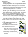
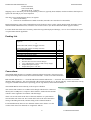
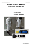
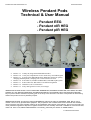
Pendant Pod User Manual Rel 3.3 Pocket Neurobics Wireless Pendant Pods Technical & User Manual - Pendant EEG - Pendant nIR HEG - Pendant pIR HEG • • • • • • • Release 1.1 12 May 04, Program/Pod/Standalone modes Release 2.0 17 July 04, simplification to two modes only: Pod and Program Release 2.1 10 August 04, added BoExplorer & BioEra support for quickly changing Pendant profile, sampling rate vs link resilience to errors. Release 3.0 26 October 04, includes Pendant HEG, both nIR & pIR system Release 3.1 29 November 04, adds tables of rf channel assignment Release 3.2 5 March 05, ed. to Connections Release 3.3 6 July 2005 general revision, new images IMPORTANT NOTICE: Minder Labs PL MAKES NO WARRANTIES, EXPRESS OR IMPLIED, INCLUDING, BUT NOT LIMITED TO, ANY IMPLIED WARRANTY OF MERCHANTABILITY OR FITNESS FOR A PARTICULAR PURPOSE, beyond product defect warranties expressly given in the body of this document. The User is responsible for determining whether this product is fit for a particular purpose. IMPORTANT NOTICE: This product is NOT FOR MEDICAL USE and is solely for PERSONAL USE. Not for use by children. Not for use by photosensitive epileptics. The prospective user is advised that some individuals with sensitive nervous systems may have negative reactions to neurofeedback and/or light & sound training. This can be the case even under professional guidance. Reports of negative reactions are rare & mostly anecdotal. If headaches or discomfort arise, cease use. Prior to use, READ USER MANUAL in its entirety, particularly the Section on USER SAFETY. 1 2005 Pocket Neurobics Pendant Pod User Manual Rel 3.3 Pocket Neurobics Contents QUICK START.............................................................................................................................................................................................. 2 INTRODUCTION ......................................................................................................................................................................................... 3 USER SAFETY .............................................................................................................................................................................................. 4 CONDUCTION OF ELECTRICITY THROUGH EEG ELECTRODES ....................................................................................................................... 4 INFECTION RISK (PENDANT EEG) ................................................................................................................................................................ 4 PRODUCT CARE & MAINTENANCE...................................................................................................................................................... 4 SYSTEM RESET ............................................................................................................................................................................................. 4 RECHARGEABLE BATTERY ........................................................................................................................................................................... 4 WARRANTY .................................................................................................................................................................................................. 4 PACKING LIST ............................................................................................................................................................................................ 5 CONNECTIONS............................................................................................................................................................................................ 5 POWER UP .................................................................................................................................................................................................... 6 PUSHBUTTON FUNCTION........................................................................................................................................................................ 6 MOMENTARY PUSH: RF CHANNEL CHANGE ................................................................................................................................................. 6 LONG PUSH: MODE CHANGE ........................................................................................................................................................................ 6 SIGNAL VALIDITY ......................................................................................................................................................................................... 7 MANAGING THE WIRELESS LINK & FAULT FINDING .................................................................................................................. 7 INTEFERING SIGNALS .................................................................................................................................................................................... 7 NO CONNECTION .......................................................................................................................................................................................... 7 BATTERY MANAGEMENT ....................................................................................................................................................................... 8 APPENDIX 1: PROCEDURE TO PLACE ELECTRODES AND THE 10-20 SYSTEM ................................................................................................. 8 Quick Start The Pendant Pod system acquires a bio-signal and sends it over a wireless link to a PC application for processing and feedback. The system comprises the Pendant wireless pod with rechargeable battery, a USB port wireless dongle, and a USB port battery charger. The system can operate on any one of eight wireless channels - the Pendant Pod and the dongle need to be set to the same wireless channel. Pendant EEG Electrodes: The Pendant EEG is not supplied with electrodes – standard 1.5mm electrodes (use pure silver or tin only) (purchase five or six electrodes), earclips (purchase three or four), and conductiver paste (such as “Ten20”) can be obtained on-line from.. • http://www.telegrass.com or • http://www.rochestermed.com Before first use: • Charge the battery overnight on the battery charger which plugs into a USB port. It is a good idea to place the battery on the USB charger whenever the Pendant is not in use. If there are a shortage of USB ports, then a low cost USB expansion hub, which typically provides three extra USB ports, can be used. • Install the Windows drivers supplied for the Wireless Dongle. The Wireless Dongle plugs into a spare USB port, but appears to the software as a virtual COM port. For full instructions on installing the driver, see the file windows.htm on the minidisk supplied or download from http://www.pocket-neurobics.com/windows.htm) In fact two drivers are installed within a single installation process – a USB port driver, and a serial port driver. During installation of the driver, windows will allocate the next available serial COM port to the driver. The Biofeedback application needs to be configured to look at this port. Because these are ‘virtual’ COM ports, the 2 2005 Pocket Neurobics Pendant Pod User Manual Rel 3.3 • • • • • • Pocket Neurobics COM port number can range up to COM16 or more. The wireless dongle should be physically mounted so that it has clear line of sight to the Pendant. If BioExplorer has been purchased, plug in BioExplorer’s security dongle into a spare USB port. This security dongle will be recognised by the BioExplorer installation process and installed automatically. [Note that BioEra software (see http://www.proatech.com/products/bioerapro/ ) is also supported by the Pendants but its operation is not covered by this note.] To install BioExplorer, from the minidisk supplied (or download from http://www.cyberevolution.com) , run BEx.xSetup.exe where “x.x” is the version number. From the minidisk, copy the files from the directories \BioExplorer\Designs\ and BioExplorer\Media\ into the equivalent directories created by the BioExplorer installation. (For example: C:\Program Files\BioExplorer\Designs and C:\Program Files\BioExplorer\Media) These design files are provided as example HEG & EEG designs - BioExplorer allows the end-user to create their own protocols or for designs to be purchased from Design Specialists such as Peter Van Deusen (for more information see http://health.groups.yahoo.com/group/braintrainer ) After BioExplorer has been installed, BioExplorer’s driver for the Pendant Pod needs to be activated. To do this, run BioExplorer, then select “BioExplorer” from the menu bar, then select “Devices”. Inside BioExplorer’s device manager, select “Add..” and from the drop-down list, select “Pendant EEG”. Highlight the newly listed driver (by left clicking on it) then select “Properties” and assign to the Pendant driver the COM port allocated to the Wireless Dongle by the Windows wizard. Note that the other COM port parameters are not to be changed from their defaults, namely Baud Rate 38400, Parity none, Byte size 8 and Stop bits 1. Finally, “check” the box in front of the newly listed Pendant EEG driver to activate it. Now run a BioExplorer design by selecting “Design” from the BioExplorer menu bar, then “Open..”, and choosing one of the example designs transferred from the minidisk. First check that the design is recognising the Pendant driver by selecting “Windows” in the menu bar, then “Signal Diagram” and on the left side of the diagram note that the “Source” object has recognised “Pendant EEG” as its driver. Go back to “Windows” in the menu bar and select “Instruments1”. Turn on the Pendant using the switch at its base and note that the light on the Pendant blinks off every four seconds with the number of the wireless channel (default is blinking once for channel 1). Note that the light on the Wireless Dongle should now also be on, blinking off every four seconds. [If not, if the Wireless Dongle light is off and blinking on, then it may not be on the same wireless channel as the Pendant.] Then check the BioExplorer status bar to see whether BioExplorer is receiving the signal. Tod do this, left click of the driver displayed in the status bar until it shows “Pendant EEG on COM x”. It should show “connected” in green. Finally, to start a BioExplorer training session, select the Go button (green arrow) on BioExplorer’s command bar. Introduction This User Manual describes the variants of the wireless Pendant Pod system: • the Pendant EEG, a 2 channel EEG • the Pendant nIR HEG (near Infrared) • the Pendant pIR HEG (passive Infrared) [HEG systems measure brain bloodflow oxygenation levels. The HEG systems require a special headset sensor.] All systems are ‘pods’, meaning that their purpose is to acquire a biofeedback signal for processing by third party PC-based Biofeedback Applications. The Pendant supports two modes of operation: • Pod Mode: acquires raw signals and passes this data to PC-based Biofeedback software via a USB-wireless dongle. In the case of the Pendant EEG, the Pod allows a choice in sampling rates of 122/128/256/512 samples per second (sps) and a choice in eeg signal bandwidth of 40Hz or 48Hz (and 56Hz for special applications). For the Pendant HEG nIR, sampling rate as seen at the PC application is fixed at122sps, and in the case of the Pendant HEG pIR, is fixed at 256sps. • Program Mode: this mode is selected to allow programming of the Pendant, either to upgrade the firmware of the Pendant, or to change the Pendant profile: eg in the case of the Pendant EEG, its sampling rate and eeg signal bandwidth 3 2005 Pocket Neurobics Pendant Pod User Manual Rel 3.3 Pocket Neurobics The Pendant Pod currently supports the following Biofeedback Applications: • BioExplorer – http://www.cyberevolution.com supports quick Pendant profile change, version upgrades, & checking of current version • BioEra – http://www.proatech.com/products/bioerapro/ supports quick Pendant profile change, version upgrades, & checking of current version • Pocket Neurobics Firmware Loader – http://www.pocket-neurobics.com/upgrade.htm supports version upgrade (this is not a biofeedback application, merely a file load utility) Pendant EEG options: A derivative of the Pendant EEG, sampling at 256/512sps, implements a 50/60Hz notch filter, and thus allows an eeg signal bandwidth of up to 200Hz. This is intended for research purposes. The Pendant EEG comes standard with a 1.5mm ‘touch-proof’ electrode interface, however for special applications a modular connector interface (RJ-45) is also available. Please email info @Pocket-Neurobics.com for further information. User Safety Conduction of Electricity through EEG Electrodes To operate, EEG systems require a low resistance path to the scalp. Should these paths come into contact with lethal voltages, serious injuries or death could result. Safety is thus an imperative and Pocket-Neurobics.com have adopted best practice in this area of design: • battery operation • wireless external links to remove the possibility of PC failure & dangerous voltages conducted via wires • EEG currents between the unit and the user are strictly limited in accordance with international standard IEC601 ENSURE THAT THE UNIT IS OPERATED IN SAFE RESIDENTIAL OR OFFICE ENVIRONMENTS – DO NOT USE IN INDUSTRIAL OR HOSPITAL ENVIRONMENTS. CONNECT EEG CABLE TO PENDANT EEG UNIT ONLY – DO NOT CONNECT TO ANY OTHER DEVICE OR CONNECTOR. Infection Risk (Pendant EEG) Traditional approaches to the placement of EEG electrodes on the scalp involve abraiding the skin to reduce electrodescalp impedance (less than 5K ohms is traditionally recommended). Breaking the skin creates the risk of infection from blood-born pathogens such as HIV, Hepatitis-C, and Creutzfeldt-Jakob disease. Although there have been no reported cases of such infections resulting from EEG sessions, the U.S. Centre for Disease Control has issued guidelines recommending that electrodes be sterilised prior to re-use. With modern instrumentation amplifiers as used in the Pendant EEG, an electrode-scalp impedance of less than 5K ohms is not necessary. Values less than 40K ohms are quite serviceable. It is therefore recommended that skin not be abraided. Both cup electrode and saline-solution electrodes can perform satisfactorily without abrasive skin preparation. When using conductive electrode paste & metallic cup electrodes, the recommended procedure is to first rub conductive paste on the site, then add more paste to the site for bulk, then apply the electrode (filled to excess with paste). Product Care & Maintenance System Reset The Pendant Pods can be reset by turning off the device via the switch at the base of the unit. Rechargeable Battery A 9V NiMH rechargeable battery is supplied with the unit. The unit can operate continuously for up to 7 hours (Pendant EEG and Pendant HEG pIR) or 3 hours (Pendant HEG nIR) after overnight recharge. If the Pendant Pod is used only irregularly, please remove the battery from the unit prior to storage. Shelf-life for a fully charged battery is a few weeks. The battery should be good for at least 300 charge cycles. Warranty The Pendant Pods are warranted against electrical failure for 30 days from date of purchase (see exceptions below). If, within this 30 day period, the unit ceases to function with it not having experienced physical damage to the case, it, together with its wireless dongle (do NOT return electrodes, headsets or charger), may be returned to: 4 2005 Pocket Neurobics Pendant Pod User Manual Rel 3.3 Pocket Neurobics Pocket Neurobics 20A Consul Road, Brookvale 2100, Australia Shipping costs to the factory are the responsibility of the user (typically about US$30). Pocket Neurobics shall repair or replace the unit and pay for return shipment. The unit is not warranted against abuse, nor against • failure of the battery • corrosion or contamination of EEG electrodes (electrodes are considered a consumable) Replacement battery units can be obtained from local electronics stores such as Tandy. Replacement electrodes can be ordered from Rochestermed.com, TeleGrass.com or other sources. (See Pocket-Neurobics home page for details.) For units which fail whilst out of warranty, and not having suffered physical damage, a service fee of US$100 for repair or replacement shall be applicable. Packing List Pendant EEG w. touch-proof electrode interface (electrodes not supplied) or Pendant HEG nIR (headset normally included) or Pendant HEG pIR (headset normally included) 9V rechargeable battery USB-wireless dongle USB port 9V NiMH battery charger Retractable USB extension Cable User Manual Mini-CD including • this user manual • Windows drivers for the Wireless Dongle • Copy of BioExplorer (requires USB security dongle) • Sample BioExplorer designs • Sample BioExplorer video files 9 9 9 9 9 9 9 Connections The Pendant EEG interfaces to standard 1.5mm touchproof electrodes. The unit provides two bipolar montage EEG circuits and a Neutral electrode - a total of five EEG electrodes. Red terminals indicate the “+” electrode and black terminals indicate the “-“ electrode. The outermost red terminal identifies EEG Channel 1. The green terminal is the Neutral electrode. It is a “driven right leg” circuit and works actively to suppress 50/60Hz interference. If operating just one eeg channel, choose EEG Channel 1. The Pendant HEGs connect directly to the respective headset. The wireless link connects to a USB wireless dongle which can be connected directly into a USB port or, to improve link resilience, attached to the monitor with the velcro supplied in accordance with the images. There is an on/off switch at the base of the unit, and there is a push-button switch on the side of the unit. The switch on the side of the unit controls the setting of Pod/Program mode, and the setting of the rf channel number. For all Pendant Pods, there are two channels of data sent to the PC over the wireless link. These two channels are assigned as follows: 5 2005 Pocket Neurobics Pendant Pod User Manual Rel 3.3 Pocket Neurobics Device Pendant EEG Pendant HEG nIR RF Link Channel 1 EEG Channel 1 HEG Channel 1 Pendant HEG pIR HEG Channel 1 RF Link Channel 2 EEG Channel 2 HEG Channel 2 (for future 2ch HEG headset) Battery Voltage readout Power Up The Pendant Pods are switched on and off by a small switch on the base of the unit. Pushbutton Function The Pendant Pods have a push button switch on the side of the unit. The switch can be activated with a ball-point pen. There is also a green LED to indicate the current state of the device. The pushbutton controls the choice of • mode, either Pod mode or Program mode, and • RF Channel number [1..8] The pushbutton function is as follows: Momentary Push: RF channel change It may be required to change the RF channel number for one of two reasons: • there is interference from sources such as wireless LANs, or Bluetooth devices • there is more than one Pendant device within a range of 10 metres Both the Pendant and the Wireless Dongle need to be set to the same RF Channel. Both devices use the same mechanism to manually change the RF Channel: Activating the pushbutton with short sharp pushes will select one of the eight available RF channels. There is a four second window after each press to allow another press. If there are no more presses within that window, then the unit will change to the selected RF channel number based on the number of presses received (1 press equals rf ch1, etc). Following this four second window, the LED will flash according to the RF channel selected ( a single flash for rf ch1, etc). Whilst the Wireless Dongle is receiving a valid signal from a Pendant Pod, the green LED on the Dongle will be steady on, and the RF channel number will flash off. When the Dongle is not receiving a signal, the LED will be steady off, and the RF channel number will flash on. Similarly, when the Pendant is in Pod mode, it’s LED will be steady on, indicating that it is transmitting, and will flash off the RF Channel number, whereas in Program mode, it’s LED will be off and the RF Channel number will flash on. Changing the RF Channel number via the pushbutton on the Pendant, will also cause the RF Channel number of the Wireless Dongle to change in sympathy, if they begin on the same RF Channel number. Also note that the Biofeedback Application software may allow the user to change the RF Channel number of the Wireless dongle. Long Push: Mode change Pressing the button for greater than two seconds will toggle between modes: • Pod Mode: acquires raw biofeedback signals and passes this data to PC-based Biofeedback software via a USB-wireless dongle. The Pendant EEG is shipped with 256sps/40Hz as the default profile, however other profiles (ie other sampling rates and bandwidths) can be selected if this function is supportd by the Biofeedback Application. To reprogram the Pendant, it first must be placed on Program Mode. Note that the Pendant Pod passes advice on the current sampling rate to the Biofeedback Application, and the Biofeedback Application will automatically switch to the correct sampling rate. • Program Mode: this mode is selected to allow 6 2005 Pocket Neurobics Pendant Pod User Manual Rel 3.3 • • Pocket Neurobics Changing Profiles: ie changing the sampling rate or EEG signal bandwidth, or A general upgrade of the Pendant Pod’s firmware as new features are introduced. To identify the version of the firmware on your unit, the Biofeedback Application may have a tool specific to the Pendant Pod labelled “About”. The Pendant needs to be in Program mode to activate this function. The serial number and version of the firmware of the Wireless Dongle and other devices that the dongle may have “discovered”, such as a Pod, are reported to the Biofeedback Application. Version numbers appear similar to: • “Dgl20x” – wireless dongle version 20x • “e0-20x” - Pendant EEG version 20x • “h0-20x” - Pendant HEG nIR version 20x • “h1-20x” – Pendant HEG pIR version 20x The About function will also identify a serial number such as: • “sn12345678” Signal Validity The Pendant Pods transmit information to the Biofeedback Application regarding the validity of the raw biofeedback data. This information will typically appear in the Status Bar of the Biofeedback Application: • • • Pendant EEG: the magnitude of the EEG signal. Where the EEG signal is excessive, perhaps due to a poorly contacting electrode, the signal will be flagged as invalid. Pendant HEG nIR: excessive or insufficient signal. Excessive signal can be compensated for by placing a tissue between the skin and the sensor. Pendant HEG pIR: thermocouple sensor not connected. Managing the wireless link & Fault Finding Intefering signals The 2.4Ghz band is shared with Bluetooth, some wireless LANs, microwave ovens, and some video and sound surveillance systems. To help prevent interference, and to allow multiple devices to operate in close proximity, eight RF channels are provided. So, in the presence of an interfering signal, which will be evidenced by synchronisation errors being reported by the Biofeedback Application, first recourse is to try a different rf channel. If this is not successful, note that signals at these frequencies do not pass thru objects, but rather will bounce off walls etc. Thus, isolating systems thru partitions etc will generally be effective. Supplied with your unit is a USB extension cable, and this can be used to either improve the line-of-sight between the Pendant and the Wireless Dongle (for instance by velcroing the wireless dongle in an elevated position), or by hiding the wireless dongle away from interfering signals. Maximum range (~5m), is best assured by elevating the dongle. Also note that the resilience to RF link errors will be significantly improved by reducing the sampling rate of the Pendant EEG (ie changing the Pendant EEG Profile). Reducing the sampling rate from 512sps to 256sps or from 256sps to 122/128sps, will improve resilience to errors. No Connection If the Biofeedback application is not synchronised to the incoming signal, check the following: • Is there more than one Pendant Pod in the vicinity? If so, are they transmitting on the same RF Channel? • Is the Green light on the Wireless Dongle flashing? If not, the Wireless Dongle is faulty 7 2005 Pocket Neurobics Pendant Pod User Manual Rel 3.3 • • • Pocket Neurobics Is the Green light on the Wireless Dongle mostly on? If not, then the problem rests with the Pendant. Is the Pendant in Pod mode (ie is it’s light mostly on)? Is the Pendant on the same RF Channel as the Wireless Dongle? If the Green light on the Wireless Dongle is mostly on, then the problem lies with the PC or Biofeedback Application. Has the Biofeedback Application selected the correct virtual COM port, and is the Parity for this port set to “none”? Has the Biofeedback Application activated the virtual COM port? Does the ‘design’ for your Biofeedback Application specifically select the Pendant Pod, or has it selected another acquisition device? Battery Management The Pendant Pod advises the Biofeedback Application when battery is low. This information is usually presented in the Application's Status Bar.The battery can be recharged overnight, which should give continuous operation for about 3 or 7 hours. It is therefore good practice to leave the battery on charge each evening – note that the battery can be left on charge indefinitely. Appendix 1: Procedure to place Electrodes and the 10-20 system To measure a brainwave signal, the electrodes can either be in pairs, with the difference in voltage between the two electrodes captured (this is called bipolar mode), or there can be a common probe to which all other (unpaired) electrodes are referenced. This is called referential or monopolar mode. The bipolar mode has the advantage of being able to measure the differences between various parts of the brain, whilst the referential mode allows multiple signals whilst minimising the number of electrodes. Both modes are in common usage. Note that the reference probe can be attached to the body anywhere, however most commonly it is attached to the ear on the side of the brain being studied. If both hemispheres are being exercised, the reference probe can be attached to either ear or to both (using a “linked-ear” cable), or along the mid-line of the brain. It is also required to attach a neutral connector to the user to ensure that the user and the eeg machine are of equal potential. This is done in such a way so as to ensure only minute currents flow between the user and the instrument. The neutral electrode is usually an earclip. The 10-20 system describes the locations on the scalp as shown below. The symbols F, C, P, O, and T are short hand for the major lobes of the brain: frontal, central, parietal, occipital and temporal respectively, whereas the numeric subscripts describe a location on the lobe, with odd numbers on the left hemisphere and even numbers on the right. Note that a subscript of "z" denotes the midline point. For a single active probe (ie 1 channel referential montage) a commonly used point for the active electrode is either C3, C4 or Cz with the reference on one or both ears. For two active electrodes the most common points are C3 and C4, with a reference at the ears or on the mid-line. In a clinical environment it would be common for the electrodes to be relocated from time to time during a session, with specific regimens to treat specific conditions. 8 2005 Pocket Neurobics