1
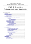
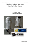
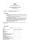
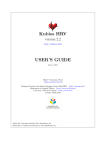
YORK BIOFEEDBACK
w w w. yo r k - b io f e e d b a c k . co . u k
© Glyn Blackett
Heart Rate Data Collection
Software Application User Guide
Table of Contents
1 Introduction.......................................................................................................1
2 Launching the Application.................................................................................2
2.1 Hardware Set-up...................................................................................2
3 Physiological Parameters..................................................................................3
4 User Interface...................................................................................................3
4.1 Standard Controls (Start / Stop, etc.)....................................................3
4.2 Heart Rate Display and Controls...........................................................4
4.3 Heart Rate Calibration Displays............................................................4
4.4 Recording Data.....................................................................................5
4.5 Spectral Analysis Display......................................................................6
1 Introduction
This guide introduces the Heart Rate Data Collection application, part of York Biofeedback's MindBody Training Tools suite. This set of applications is designed to develop skills in mind-body
awareness and self-regulation, particularly in a context of mindfulness and meditation practice. This
guide shows you how to use the application.
The Heart Rate Data Collection application was not designed as a biofeedback application (though
it can be used for simple visual feedback). Rather it's purpose is simply to record heart rate data for
use with third party analysis software. An example of such a software is Kubios HRV, developed by
the University of Eastern Finland.
The guide assumes that you have read the Software Installation and Set-up Guide, and therefore
know how to start the application.
The user interface is covered in section 4. When you start the application, you can first make sure
that you are accurately detecting heart beats, then you initiate a timed period during which data is
recorded to a text file for later analysis.
The application works with several devices. For an up to date list of supported hardware, please see
the York Biofeedback website. Some of these devices use a PPG sensor to detect heart rate, others
use ECG – the software works with both modalities.
Heart Rate Data Collection Application User Guide, copyright Glyn Blackett
page 1
2 Launching the Application
1
Figure 1 – Heart Rate Variability Tab of the Platform Application
Figure 1 above shows the Heart Rate Variability tab of the Platform application. Press the button
labelled 1 to launch the HR data collection application. Make sure you have your BioEra licence
key (dongle) inserted into a USB socket. After a few seconds two new windows will appear on your
screen.
2.1 Hardware Set-up
The physical aspects of hardware set-up (how to connect and use your sensors, etc.) are dependent
upon the type of amplifier you are using, and are covered in a separate document (Hardware Set-up
Guide).
Before you start the application you configure the Device set-up
options, accessible by clicking a button in the Set-up tab of the
Platform. In the dialog, select the type of amplifier (biofeedback
device) you are using, in the HR source control. In the same
dialog you should select the frequency of your local mains (e.g.
50Hz in the UK). All the source settings are remembered the next
time you start the Platform. See the Installation and Set-up Guide
for further details of device set-up.
Figure 2 – amplifier status
One of the device options is 'Simulator'. In simulator mode, you
can learn how to use the software without the encumbrance of sensors, leads etc. (The application
simply uses recorded data as a source.)
Once you have started the application, you should see your device selection reflected in the device
status display in the top right corner of the main window (see figure 2). The lamp (shown as a red
square in figure 2) should change to green when you press the play button. If you do not see this
happen, it means that the application has not been able to establish a connection with your device.
Check it is plugged in and that the batteries are not flat.
For some devices, you'll see a button rather than just text. Pressing this button opens up a dialog
Heart Rate Data Collection Application User Guide, copyright Glyn Blackett
page 2
that allows you to adjust settings related to the device, such as COM port. The specifics depend on
the device – see the Hardware Set-up Guide for more details.
3 Physiological Parameters
Heart rate data is derived from either ECG or photoplethysmograph (PPG) signal, depending on the
device type selected (see device set-up options on the set-up tab of the launcher).
In either case the “raw” signal is displayed in the user interface – see figure 5 below. The heart beat
detection algorithm uses a threshold, which is shown as a dotted yellow line in figure 5. See section
4.1.3 below for more on heart rate calibration.
Figure 5 shows an ECG signal. In the case of PPG the “raw” signal displayed is actually the first
derivative of the PPG signal (used because beat detection is more reliable).
4 User Interface
This section explains the charts in the application's user interface, and how to use the controls.
Figure 3 below shows the application's window.
1. Standard Controls
2. Heart Rate Display
8. Raw ECG
Display
3. Spectral
Analysis
Display
7. Beat
Detection
Display
6. Heart Rate
Numeric Displays
4. Data Recording Controls
5. Beat Detection
Threshold Control
Figure 3 – User Interface
4.1 Standard Controls (Start / Stop, etc.)
A set of buttons – Play, Stop and Pause – are labelled 1 in figure 3 above. The same in all the
applications in the suite, they should be self-explanatory.
Heart Rate Data Collection Application User Guide, copyright Glyn Blackett
page 3
4.2 Heart Rate Display and Controls
1
2
3
Figure 4 – Heart rate display and controls
The chart shows heart rate in red. It has three associated controls (1 to 3 in figure 4):
Period
This controls the length of time it takes for the trace to traverse the whole chart from
right to left – or in other words the horizontal range.
HR Range Controls the difference between the upper and lower limits of the Heart Rate display
(red trace, upper chart).
Change this if the HR trace looks too bunched up or stretched out vertically.
Centre HR This button is used to centre the red heart rate trace to the middle of the chart – i.e.
it causes the trace to be shifted either up or down (but without changing the scale).
Trace
You can use this if the trace is disappearing off the top or bottom of the chart. The
(Button)
trace is automatically centred during the first minute of the session.
Heart rate and average heart rate are shown in numeric displays (6 in figure 1).
4.3 Heart Rate Calibration Displays
1
Figure 5 – Heart rate calibration displays
In figure 5 above, the upper chart shows raw ECG signal from which heart rate is computed. The
yellow dotted line shows the threshold for beat detection: each time the sharp upward spike crosses
Heart Rate Data Collection Application User Guide, copyright Glyn Blackett
page 4
the dotted line a beat is detected.
If you're using a PPG-based device this trace will look different, but the same concept applies – the
yellow dotted line indicates the beat detection threshold.
The combo box control 'Threshold Level' (labelled 1 in figure 1) can be used to fine-tune the
threshold level, moving it higher or lower so as to give the most reliable beat detection.
The lower chart shows beat detection in a digitised form. Note that some basic artefact exclusion
methods have been applied.
4.4 Recording Data
1
2
3
4
5
Figure 6 – Data recording controls
The application writes HR data to a simple text file, which can be saved for analysis. The data
written is simply a series of consecutive inter-beat intervals measured in milliseconds. Data is
written for a timed period. You can set the length of this period using the combo box control 2 in
figure 6 above.
Once you are assured that you have an adequate signal, press button 4 (figure 6) to start recording.
The 'Lead Time' control (1 in figure 6) allows you to set a short period before recording – this is for
when you're recording yourself and need a few seconds to become still after pressing the button.
A numeric display (3in figure 6) shows your progress through the timed period, and another
numeric display (6 in figure 1) shows each inter-beat interval.
At the end of the timed period the application automatically switches off. You can then give a name
for your data file, which will be saved in the user data location (see the Installation and Set-up
Guide for details.
Heart Rate Data Collection Application User Guide, copyright Glyn Blackett
page 5
4.5 Spectral Analysis Display
1
Figure 7 – Spectral analysis chart
This chart displays the results of spectral analysis of the inter-beat interval data. The meaning of
spectral analysis is rather technical and is described at greater length in the HRV Application User
Guide. It is included here to give you an impression of the degree of coherence. Good coherence
looks like a single clear strong peak in the green segment with other segments being relatively flat.
The numeric displays show the percentage of the total power within each of the three frequency
bands (VLF, LF and HF), and additionally the LF to HF ratio.
There is one control associated with the chart (1 in figure 7).
DFT Samples
This combo box controls the number of data points (IBI) used for the spectral
analysis. In effect this controls the size of the time window over which the
spectral analysis is calculated. Assuming an average heart rate, a setting of 256
gives a window of around 3.5 minutes.
Heart Rate Data Collection Application User Guide, copyright Glyn Blackett
page 6