1
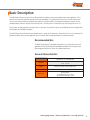
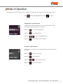
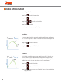
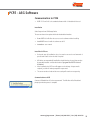
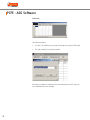
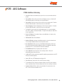
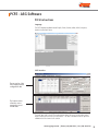
Digital Torque Wrenches
TW Model User Manual
ASG, Division of Jergens, Inc.
15700 S. Waterloo Road | Cleveland, OH 44110-3898
Phone: (888) 486-6163 | Fax: (216) 481-4519
Email: [email protected] | Web: www.asg-jergens.com
Table of Contents
Basic Description
Recommended Use
General Characteristics
Care Guidelines
Modes of Operation
Language Mode
Unit Mode
Date Mode
Track Mode
Peak Mode
Set Mode
Preset Mode
Recall Mode
Upload Mode
Clear Mode
COMMS Mode
PCFE - ASG Software
Communication with PCFE
PCFE Interface Glossary
PCFE Instructions
PCFE Language
The PC Front End - Whole Page
The PC Front End - Top of Page
Set a Preset
The PC Front End - End of Page
Continuous Upload
Upload All
Clear Wrench Data
Clear Results
Unit Conversion
Connection Status
Torque Wrench Calibration
Optional Wireless Technology
2
Basic Description
The Digital Torque Wrench is a state-of-the-art hand-held device suitable for both torque auditing & also torque application. These
precision tools have both high torque accuracy & also high repeatability. For product portfolio cohesion, this model torque wrench
uses the same organic LED display, membrane type keypad, user interface and also PC based data management software as other
standard products within this range of electronic torque tools. Training up time is minimal with a key feature being the ease of use.
These products are demonstrated to have better than 1% accuracy. They are both simple to set and calibrate and come complete with
fully traceable ISO 6789-2003 certification.
The Digital Torque Wrench has both visual and audio alarms to signal good or bad torque. Along with this, there is a visual battery life
indicator and alarms for preset value approach, fastener overload, range overload and maximum mechanical overload.
Recommended Use
The Digital Torque Wrench is specifically designed for use in all industrial sectors and
applications where high accuracy and repeatability combined with a complete torque
data management and control system are standard requirements.
General Characteristics
Accuracy
Right hand side torque = 1%
Left hand side = 1% of Actual Reading
Resolution
0.01 N.m - 50 N.m
0.1 N.m - 1000 N.m
Alarms
Preset Value Approach, Range Overload,
Mechanical Overload, Low Battery, Memory Full
Memory Capacity
2094 Values
Battery Life
Sleep Mode: 5,000 Hrs
Operational Mode:
For Standard Model: Up to 120 Hours
Optional Wireless Model: Up to 40 hours
www.asg-jergens.com | Phone: (888) 486-6163 | Fax: (216) 481-4519
3
Basic Description
Care Guidelines
• These instruments should be handled with care
• Do not subject to torque loads in excess of the model range
• Do not use tool to loosen fasteners tightened beyond maximum tool capacity
• Using non-linear extensions may affect the torque accuracy
• Using torque extensions will increase the torque applied
• Do not operate tool unless it has been powered on and the display screen can be
read clearly
• Do not drop or subject to impact blows
• Provide adequate storage to protect from damage
• Adhere to safety instructions
• As torque is length dependent, therefore torque should be applied to the center
of the torque wrench handle
Changing the Battery
Step 1: Unscrew the metal end cap on the handle of the wrench
Step 2: Remove the four AA cell batteries and replace with new
Step 3: Screw back the metal end cap
Step 4: Turn on the wrench and check to ensure the date and time are both set correctly
Step 5: Practical usage time for rechargeable batteries is shorter than for standard batteries
Ratchet Head Guidelines
• Store in a dry location
• Oil frequently to prevent ratchet head seizing
• Do not use external forces on ratchet (i.e. hammer)
• Do not exceed specified torques
• Max Torque for 1/4” Ratchet = 30 Nm
• Max Torque for 3/8” Ratchet = 135 Nm
• Max Torque for 1/2” Ratchet = 340 Nm
4
Modes of Operation
Torque reading starts at 5% of maximum with an accuracy of 1% beginning at 10% of maximum (threshold to maximum span).
Press
to select the required Menu option and
to select.
Language Mode - Keypad Function
The languages of operation available to the user are: English, Chinese, French,
German, Italian, Polish, Portuguese, Russian, Spanish
Step 1: Press
to scroll to the Language Menu
Step 2: Press
to enter Language Menu
Step 3: Press
Step 4: Press
to scroll to the language required
to confirm operation in this language
Unit Mode - Keypad Function:
The following units of measurement are available: kgf.cm, kgf.m, cN.m, N.m, ozf.in,
lbf.in, lbf.ft
Step 1: Press
to scroll to the Units Menu
Step 2: Press
to enter Units Menu
Step 3: Press
Step 4: Press
to scroll to the units required
to confirm selected units
www.asg-jergens.com | Phone: (888) 486-6163 | Fax: (216) 481-4519
5
Modes of Operation
Date - Keypad Function:
Step 1: Press
to scroll to the Date Menu
Step 2: Press
to enter Date Menu
Step 3: Press
Step 4: Press
to scroll to set the min/hour
to confirm
To set the day/month/year, repeat step 3 and step 4
Track Mode:
As torque is applied, the driver will actively display the applied torque reading from
5% up to the max span of the device. On removal of the torque load the display will
return to zero.
Step 1: Press
to scroll to Track Mode
Step 2: Press
to operate in Track Mode
Peak Mode:
In Peak Mode, on condition that the torque loaded is above 10% of the tool span,
then the maximum torque reading will remain displayed when the torque load is
removed. The user has the option to store the reading in memory. If storage of the
reading is not required, the user may continue to the next measuring task.
Step 1: Press
to scroll to Peak Mode
Step 2: Press
to operate in Peak Mode
Step 3: Press
to store the peak value if required. If storage is not required, then apply new torque.
6
Modes of Operation
Set Mode:
This mode allows the user to set the limits for torque. The operator can choose to
set torque values by % or by tolerances. After, in operation of these presets the
OLED display will be green approaching preset tolerances and will change to red if
exceeded.
Step 1: Press
to scroll to Set Mode
Step 2: Press
to select Set Mode
Step 3: Press
to scroll to set by % or set by tolerance
Step 4: Press
to scroll to scroll to required present number (1 to 99)
Step 5: Press
to confirm preset number selected
Step 6: Press
to set nominal value and
to confirm
Step 7: Press
to set your low value and
to confirm
Step 8: Press
to set your high value and
to confirm
Step 9: Once the parameters have been confirmed the operator can find the task within
Preset Mode. Use
to select Preset Mode from the main menu to find the task.
To set a preset as a +/- % deviation of the nominal value, please select “Set Torque”
and then select “by %”
www.asg-jergens.com | Phone: (888) 486-6163 | Fax: (216) 481-4519
7
Modes of Operation
Preset Mode:
This mode allows the user to operate using target, minimum and maximum
parameters prepared in Set Mode. Depending on the max torque loaded, there are
relevant warning signals activated.
• Passing Min. Value: the green LED on keypad will flash and the buzzer will
sound intermittently. The OLED display will change to orange
• Passing Nom. Value: the green LED on keypad will switch on and the buzzer will
sound continuously. The OLED display will be green
• Passing Max. Value: The red LED will flash continuously and the buzzer will
sound continuously and the OLED will change to Red.
Step 1: Press
to scroll to Preset Mode
Step 2: Press
to enter Preset Mode
Step 3: Press
to select your preferred preset number (1 to 99)
Step 4: Press
to operate within this preset parameter
Step 5: Press
to store the applied torque (torque and angle) if required
Recall Mode:
This mode allows the user to view the stored torque and angle data. Only locations
containing data will be displayed. Note that as data is stored the locations are
populated sequentially from 01 to 2094.
8
Step 1: Press
to scroll to Recall Mode
Step 2: Press
to enter and view memory locations, results and functions
Step 3: Press
to scroll through locations that contain data
Modes of Operation
Upload Mode:
This mode allows the user to upload stored torque data. In Upload Mode, the driver
must be connected to a PC running the PC FRONT-END Software (PCFE) via the USB
Port on the driver and PC.
Step 1: Press
to scroll to Upload Mode
Step 2: Press
to enter Upload Mode
Step 3: Press
to select “From” and
location to upload
to select the first sorted data
Step 4: Press
to confirm “From” location
Step 5: Press
uploaded
to select “To” location and
Step 6: Press
to confirm. You are asked if you are sure, press
for end location to be
to confirm
COMMS Mode:
This mode allows the user to select the method for communication. The standard
model allows communication by standard USB Cable to the included software. For
communication by ASCII or BINARY the wrench will need physical modifications in
advance.
Step 1: Press
to scroll to COMMS Mode
Step 2: Press
to enter COMMS Mode
Step 3: Press
to select the method of communication and
to confirm
Note: For standard communication to the included software program, select ‘PCFE’
www.asg-jergens.com | Phone: (888) 486-6163 | Fax: (216) 481-4519
9
Modes of Operation
Clear Mode:
This mode allows the user to clear the stored torque data from an individual or range
of locations. Note: Before clearing the selected range and as a safety precaution, the
user will be asked are they sure they wish to clear selected data. This can be done by
pressing the confirm button.
10
Step 1: Press
to scroll to Clear Mode
Step 2: Press
to enter Clear Mode
Step 3: Press
to select “From” range to be cleared and press
Step 4: Press
to confirm “To” range to be cleared
Step 5: Press
to confirm and you will be asked if you are sure
Step 6: Press
wrench memory
to confirm and that the range of the data is cleared from the
PCFE - ASG Software
Communication to PCFE
• PCFE: ‘PC Front End’ is the standard software which is included with the tool
Installation
Select Setup.exe from USB Storage Device
The user can choose from options within the window below interface
• Demo PCFE: this will allow the user to test the software without installing
• Install PCFE.exe: to install the software to the PC
• Instructions: user manual
Install the PCFE.exe
• During the steps for installation, there is a search to ensure the .net framework is
present and installs it from the web if required
• USB drivers are automatically installed but should there be the need, they can also
be manually installed – and can be found at C:/program files/PCFE/Front-end/
USB drivers
• After installation the PCFE Icon will appear on the desktop. No password is
required; just click OK when prompted for a password
• The screen can be re-sized and the new setting will remain on next opening
Communication to PCFE
Connect a USB cable from PC to the torque wrench. The HID driver will self-install and
prompt you when the process is complete.
www.asg-jergens.com | Phone: (888) 486-6163 | Fax: (216) 481-4519
11
PCFE - ASG Software
Select Port
There will be two options:
• Com Port 1: this will allow you to connect the older type tools using the RS232 cable
• The serial number(s) of the wrench connected
Note: After you configure or view data on the tool and disconnect from PCFE, select Com
Port 1 afterwards to close the virtual port.
12
PCFE - ASG Software
PCFE Interface Glossary
• Select Port: Select communication port you wish to use to communicate with the
wrench
• Current Mode: Select mode you wish the tool display on start up. Selection will
take effect after data is stored using ‘store to wrench button’
• Current Units: Select the torque units you wish the tool to operate with. Selection
will take effect after data is stored using ‘store to wrench button’
• Current Language: Select the language you wish the tool to operate in. Selection
will take effect after data is stored using ‘store to wrench button’
• Tool Span: For these torque tools, the quoted accuracy is 1% of actual reading
from 10% to 100% of the actual reading. ‘Tool Span’ will indicate the 100% limit
for this specific driver
• Period of Calibration: Set number of days to next calibration or it can be set by
number of measurements
• Calibrated On: Date of last calibration
• Activate Calibration: Activates the calibration option in the tool on-board menu.
You must begin calibration before the wrench powers down
• Reset the Wrench: Allows tool reset. All calibration data/settings stored in the
Driver will be cleared and default calibration values for a calibration span will be
programmed. This is not an alternative method for calibration
• Power Off Wrench: Allows soft power down of the driver
• Store to Wrench: Store all current PC front settings to driver. Driver will
automatically power down after store
• Load from File: Loads a previously created file containing preset data into the PCFE
front preset window (top left)
• Save to File: Saves PCFE displayed preset data to file
• Clear all Presets: Clears presets from the PCFE presets window
• To set a Preset: Click on any preset location number in the PCFE presets window.
Set the required nominal, min, max tolerance and units. Store settings to the driver
• Continuous Upload: Allows real time communication of measurements to the
PCFE. Driver must be connected to the PC
www.asg-jergens.com | Phone: (888) 486-6163 | Fax: (216) 481-4519
13
PCFE - ASG Software
PCFE Interface Glossary (Continued)
• Upload All: Uploads & displays all stored driver measurement data in the PCFE
data window
• Clear: Clears the driver measurement data displayed on the PC
• Clear Wrench Data: Clears the driver measurement data displayed on the PCFE
and in the driver
• Unit Conversion: Allows user to change the units of the displayed measurement
data on the PCFE
• Sort by Preset: Sort the displayed measurement data and group according to
ascending preset numbers
• Save as an Excel File: Save the current displayed measurement data as an excel
file. The PCFE measurement data window displays stored wrench measurements
showing driver memory location, date and time, torque value
PCFE Instructions
No password is required when starting the PCFE software, click OK when the password
entry screen appears.
14
PCFE - ASG Software
PCFE Instructions
Language
The PCFE languages available include: English, French, German, Italian, Polish, Portuguese,
Spanish, Russian and Chinese
PCFE Interface
The top section of the
PCFE displays wrench
configuration data
The bottom section
allows the user to
manage the stored
wrench data
The right upper half of the PCFE window displays data such as tool serial number, make,
model, torque span and units of measurement. The date of calibration and the period of
calibration are also shown in this section.
www.asg-jergens.com | Phone: (888) 486-6163 | Fax: (216) 481-4519
15
PCFE - ASG Software
PCFE Instructions (Continued)
Serial Number
Current Settings: mode,
language, units, power
off time
Model
Make
Wrench Span and
Units: change these
and tool must be
recalibrated
Activate Calibration
Date of calibration,
calibration co-efficients,
duration of calibration
Store to Wrench:
stores any changes
the user makes to
the wrench current
settings
The left upper section displays the presets stored in the tool - the user can choose to use
the PCFE to set the presets or it can be done manually on the tool.
The bottom half of the PCFE window displays any stored measurements on the tool. It
displays location, number of data on tool, date and time of reading, torque readings, preset
data, units of measurement and the mode that was used to take the torque measurement.
16
PCFE - ASG Software
PCFE Instructions (Continued)
Set a Preset using the PCFE
Step 1: Ensure the wrench is connected to the PCFE software selected using ‘Select Port’
Step 2: Select the preset number or location from 1 to 99 you wish to set
Step 3: When the pop up window appears fill in required fields and press OK
Step 4: Select ‘Store to Wrench’. Data is written to the tool
Step 5: Select Preset option on the tool and select the required preset
www.asg-jergens.com | Phone: (888) 486-6163 | Fax: (216) 481-4519
17
PCFE - ASG Software
PCFE Instructions (Continued)
The lower section of the PCFE allows the user to view stored results from the wrench. These
results can then be saved as an excel file for further analysis and to offer the user complete
traceability of their torque measurements.
Shows Com Port
Selected
Shows that
the Wrench
is Connected
Current Software
Version
Indication Bar
Each row will display the following: time and date of torque operation, torque value and units.
If it’s a preset result then the minimum and maximum tolerances are displayed along with the
nominal setting
The “Mode” column will display the function that was used for the torque operation. In the
example you can see peak and preset
Continuous Upload: When the wrench is connected to the PCFE and this is selected then the
user can take reading’s and by pressing confirm on the wrench the result will be automatically
updated to the PCFE
Upload All: Once the tool is connected to the PCFE, selecting this option will upload all the
wrench stored measurements to the PCFE
Clear Wrench Data: Selecting this option will clear the stored results from the tool memory
Clear Results: Selecting this button on the PCFE will clear the displayed PCFE results
Unit Conversion: Selecting this button allows the user to convert the displayed PCFE readings
between N.m, cN.m, lbf.ft, lbf.in, kgf.m and kgf.cm
18
Torque Wrench Calibration
Calibration is achieved using 8 measuring points, namely 10%, 20%, 60% and 100% of
maximum span in both clockwise and counter-clockwise directions. In Calibration Mode the
tool will automatically display these measuring point values initially for the right hand and
then for the left hand. All products should be 1% accurate.
• De-stressing wrench implies that the wrench is torqued to its maximum span
• Ensure date & time on tool are correct before calibrating
• Calibration Mode is only accessible through the master and distributor versions of the
PCFE software
• Calibration Mode will not appear on the tool unless activated using the PCFE software
• A certified system with accuracy of 0.25% should ideally be used to calibrate
Step 1: Connect wrench to PCFE software and click the ‘Activate Calibration’ button
Step 2: Press
on the wrench to scroll to Calibrate Mode
Step 3: Place tool onto calibration unit. The reaction post should contact the center of the handle grip. The wrench would be kept perpendicular to the static torque tester. De-stress to the CW (clockwise) direction
Step 4: Press
to activate Calibrate Mode. The wrench OLED will now display a static reading of 10% of the maximum span of the wrench
Step 5: Apply torque to the tool until the reading on the calibration rig is equal to the reading on the tool (10% of maximum span)
Step 6: Press
to confirm that the first point of calibration is now set
Step 7: Next, measurement point no. 2 (20% of maximum span) will appear on the Tool OLED display. Repeat step 5 and step 6
Step 8: Next, measurement point No. 3 (60% of Maximum Span) will appear on the Tool OLED display. Repeat step 5 and step 6
Step 9: Now measurement point no. 4 (100% of Maximum Span) will appear on the Wrench OLED display. Repeat step 5 and step 6
Step 10: Repeat Step 1 to Step 9 for the left hand calibration
Step 11: Once calibration is complete select track mode on wrench. On the left hand side check wrench accuracy at 20%, 60% and 100% according IS06789-2003.
Step 12: Now de-stress on right hand side and repeat step 11.
www.asg-jergens.com | Phone: (888) 486-6163 | Fax: (216) 481-4519
19
Optional Wireless Technology
• Easy to set-up and use
• Numerous safety features prevent data loss
• To use the Digital Torque Wrench as a wireless torque wrench it should be used
together with the wireless master receiver
20