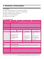
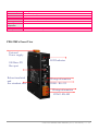
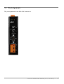
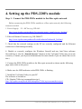
1
PDS-220Fx Series
User Manual
Warranty
All products manufactured by ICP DAS are under warranty regarding defective materials
for a period of one year, starting from the date of delivery to the original purchaser.
Warning
ICP DAS assumes no liability for damages resulting from the use of this product. ICP
DAS reserves the right to change this manual at any time without notice. The information
furnished by ICP DAS is believed to be accurate and reliable. However, no responsibility
is assumed by ICP DAS for its use, or for any infringements of patents or other rights of
third parties resulting from its use.
Copyright
Copyright 2010 by ICP DAS. All rights are reserved.
Trademark
Names used are for identification only and may be registered trademarks of their
respective companies.
PDS-220 Series User Manual (V1.0, Jun.2010) ----- 1
Table of Contents
1.
INTRODUCTION ..............................................................................................................................................................5
1.1.
WHY FIBER OPTIC SOLUTIONS?................................................................................................................................5
1.2.
WHY VXCOMM TECHNOLOGY? ................................................................................................................................7
1.3.
WHY WEB SERVER TECHNOLOGY? ..........................................................................................................................9
2.
TYPICAL APPLICATIONS FOR THE PDS-220FX ...................................................................................................10
2.1.
RS-232/485/422 DEVICE NETWORKING ....................................................................................................................10
2.2.
FIBER I/O APPLICATIONS.........................................................................................................................................11
2.3.
CONFIGURABLE FIBER OPTIC DATA LOGGER ........................................................................................................11
3.
HARDWARE INFORMATION......................................................................................................................................14
3.1.
FEATURES .................................................................................................................................................................14
3.3.
PDS-220FX SELECTION GUIDE ...............................................................................................................................16
3.4.
PIN ASSIGNMENTS ....................................................................................................................................................17
4.
SETTING UP THE PDS-220FX MODULE...................................................................................................................19
5.
CONFIGURATION VIA A WEB BROWSER..............................................................................................................26
5.1.
CONNECTING TO THE PDS-220FX MODULE ...........................................................................................................26
5.2.
NETWORK SETTINGS ................................................................................................................................................27
5.3.
IP FILTER SETTING ..................................................................................................................................................30
5.4.
COM PORT SETTINGS..............................................................................................................................................31
5.5.
MISCELLANEOUS SETTINGS .....................................................................................................................................37
6.
CONSOLE/TELNET COMMANDS LIST ....................................................................................................................39
6.1.
OPERATION FLOWCHART ........................................................................................................................................39
6.2.
SWITCHING BETWEEN INIT/NORMAL MODES .............................................................................................................40
6.3.
COMMAND LIST .........................................................................................................................................................41
APPENDIX A: LINKING TO A DEVELOPMENT PC ........................................................................................................63
APPENDIX B: FRAME GROUND ..........................................................................................................................................66
GLOSSARY................................................................................................................................................................................67
1.
ARP (ADDRESS RESOLUTION PROTOCOL) ..................................................................................................................67
2.
CLIENTS AND SERVERS .................................................................................................................................................67
3.
FIRMWARE.....................................................................................................................................................................67
4.
GATEWAY ......................................................................................................................................................................68
PDS-220 Series User Manual (V1.0, Jun.2010) ----- 2
5.
ICMP (INTERNET CONTROL MESSAGES PROTOCOL) .................................................................................................68
6.
INTERNET.......................................................................................................................................................................68
7.
IP (INTERNET PROTOCOL) ADDRESS ............................................................................................................................68
8.
MAC (MEDIA ACCESS CONTROL) ADDRESS ................................................................................................................68
9.
OPTICAL FIBER ..............................................................................................................................................................68
10.
PACKET .....................................................................................................................................................................69
11.
PING ..........................................................................................................................................................................69
12.
RARP (REVERSE ADDRESS RESOLUTION PROTOCOL)...........................................................................................69
13.
SOCKET .....................................................................................................................................................................69
14.
SUBNET MASK...........................................................................................................................................................69
15.
TCP (TRANSMISSION CONTROL PROTOCOL)..........................................................................................................70
16.
TCP/IP......................................................................................................................................................................70
17.
UDP (USER DATAGRAM PROTOCOL) ......................................................................................................................70
FAQ .............................................................................................................................................................................................71
1.
HOW DO I ACCESS A REMOTE PDS-220FX THAT IS SITUATED BEHIND AN NAT OR FIREWALL? ......................................71
2.
HOW DO I OPEN A VIRTUAL COM PORT GREATER THAN "COM 9" BY CALLING CREATEFILE() WIN32 API?.................72
3.
DOES THE VXCOMM DRIVER (PC) SUPPORT AUTO-RECONNECTION AFTER FIXING A NETWORK BREAK? ...............73
4.
WHY DOESN'T THE VXCOMM DRIVER (PC) RECEIVE DATA FROM THE PDS-220FX MODULE? ................................74
5.
DOES TRANSMISSION SPEED BECOME FASTER WHEN A SERIAL DEVICE IS WORKING WITH SERIAL TO FIBER OPTIC
DEVICE SERVERS? ...................................................................................................................................................................75
6.
WHY DOES THE PDS-220FX MODULE FAIL ON A PUBLIC INTERNET CONNECTION? ..................................................77
7.
CAN I USE THE SETCOMMSTATE( ) API TO CHANGE THE BAUD RATE/DATA FORMAT SETTINGS OF A VIRTUAL
COM PORT? ...........................................................................................................................................................................79
8.
HOW MANY PCS CAN BE CONNECTED TO A SINGLE PDS-220FX DEVICE?..................................................................79
9.
CAN I SEARCH FOR OR CONNECT TO THE PDS-220FX IF THE IP ADDRESS OF MY PC IS NOT IN THE PDS-220FX IP
FILTER LIST? HOW CAN I SOLVE THIS PROBLEM? .................................................................................................................81
PDS-220 Series User Manual (V1.0, Jun.2010) ----- 3
Packing List
The shipping package includes the following items:
One PDS-220Fx series hardware module
One printed quick start guide
One software utility CD
Quick start
Note:
If any of these items is missed or damaged, contact the local distributor for more
information. Save the shipping materials and cartons in case you want to ship in the future.
More Information:
Documentations
CD:\NAPDOS\PDS\PDS-220Fx\Document\
VxComm Driver (Virtual COM)
CD:\NAPDOS\Driver\VxComm_Driver
Firmware
CD:\NAPDOS\PDS\ PDS-220Fx\VxComm\Server(PDS)
MiniOS7
CD:\NAPDOS\PDS\ PDS-220Fx\OS_image
PDS-220 Series User Manual (V1.0, Jun.2010) ----- 4
1. Introduction
The PDS-220Fx series is a family of Programmable Device Servers, also known as
"Serial-to-Fiber gateways”, that are designed to enable optical fiber connectivity to be
added to RS-232/422/485 devices. The user-friendly VxComm Driver/Utility allows users
to easily turn the built-in COM ports of the PDS-220Fx series into standard COM ports on
a PC. By virtue of its protocol independence, a small-core OS and high flexibility, the
PDS- 220Fx series is able to meet the demands of every network-enabled application.
The PDS-220Fx series includes a powerful and reliable Xserver programming structure
that allows you to rapidly design robust custom Fiber optics applications. The built-in,
high-performance MiniOS7 boots up the PDS-220Fx in just one second and gives you
fastest responses.
1.1. Why Fiber Optic Solutions?
Fiber optic communication permits transmission of data over longer distances than other
forms of communication because the signals travel along the fiber with minimum loss and
no crosstalk. Fiber optics provides the following important features:
˙ Immunity to electromagnetic interference (EMI) — Motors, relays, welders and other
industrial equipment generate a tremendous amount of electrical noise that can cause
major problems with copper cabling.
˙ High electrical resistance, making it safe to use near high-voltage equipment or
between areas with different earth potentials.
˙ No sparks — important in environments that contain flammable or explosive gas.
˙ No electromagnetic radiation, and it is difficult to tap into the signal without causing
disruption, which is an important factor in high-security environments.
Because of these reasons, optical fibers have largely replaced copper wire communications
in core networks in the developed world.
PDS-220 Series User Manual (V1.0, Jun.2010) ----- 5
Applications:
PDS-220 Series User Manual (V1.0, Jun.2010) ----- 6
1.2. Why VxComm Technology?
In general, writing code for a TCP/IP program is more difficult than for a COM port
program, or perhaps the COM port communication system was built many years ago.
As a result, a new technology, VxComm, was developed to virtualize the COM ports
of the PDS-220Fx to allow up to 256 COM ports to be used on the central computer.
The VxComm driver saves time when accessing serial devices through the fiber optic
network without the need for reprogramming the COM port software on the PC.
PDS-220 Series User Manual (V1.0, Jun.2010) ----- 7
The VxComm driver controls all the details of the TCP/IP programming and with the
assistance of PDS-220Fx and VxComm technology, your COM port program will be able
to access your serial devices through the fiber optic network in the same way as it would
through a standard COM port.
PDS-220 Series User Manual (V1.0, Jun.2010) ----- 8
1.3. Why Web Server Technology?
Web server technology enables configuration of the PDS-220Fx via a standard web
browser interface, e.g. Google Chrome, Firefox, Internet Explorer or Mozilla, etc. This
means that it is easy to check the configuration of the PDS-220Fx via a fiber optic network
without needing to install any other software tools, thereby reducing the user’s learning
curve.
PDS-220 Series User Manual (V1.0, Jun.2010) ----- 9
2.Typical Applications for the PDS-220Fx
2.1. RS-232/485/422 Device Networking
--- Using Virtual COM Technology --The PDS-220Fx series is designed to allow RS-232/485/422 devices to be connected to
a fiber optic network. The VxComm utility allows the built-in PDS-220Fx COM port to be
virtualized to a standard COM port on a host PC, as shown below:
The original COM1/2
on the host PC
COM1/2 on the PDS220Fx is mapped to
COM3/4 on the host PC
COM1/2 on the PDS220Fx is mapped to
COM5/6 on the host
In the configuration above, Meter-1 is virtualized to link to COM3 on the host PC.
Therefore a program originally designed for the MS-COMM standard can still access the
meter without the need for any modification to the program.
PDS-220 Series User Manual (V1.0, Jun.2010) ----- 10
2.2. Fiber I/O Applications
The PDS series provides fiber optic I/O solution:
Linking to I-7000 Series Modules
The I-7000 series provides a variety of I/O operations, such as D/I, D/O, A/D, D/A,
Counter and Frequency Measurement, etc. The I-7000 series was originally designed to be
used with RS-485 networks, so COM2 on the PDS-220Fx can be used to link to I-7000
series modules. These modules are very robust and work well in harsh industrial
environments.
By using VxComm technology, programs on the host PC that support serial devices
can be upgraded from a RS-485 network to a fiber optic network without requiring any
modifications to the program. Refer to Sec. 2.1 for more information.
2.3. Configurable Fiber Optic Data Logger
Using the VxComm driver, PDS-220Fx + I-7000 modules can be virtualized to become
COM port + I-7000 modules located on the host PC, and then the Data Logger in the
DCON Utility can be used to access data from the I-7000 via the fiber optic network.
Signal data originating from the I-7000 modules can be analyzed using MS-Excel without
the need to create any custom programs
1. The DCON utility includes a data logger function, as show below:
PDS-220 Series User Manual (V1.0, Jun.2010) ----- 11
2. Configure the system connection, as shown below, and click the “Start” button to begin
logging data.
3. Open the log file in MS-Excel to read the log data, as shown in the example below:
PDS-220 Series User Manual (V1.0, Jun.2010) ----- 12
By using the I-7000 DCON utility and MS-Excel in conjunction with VxComm
technology, the signal data of I-7000 modules from the fiber optic network can be
analyzed without the need to create any custom programs. For more information about the
log function refer to the online help feature (English and Traditional Chinese) of the
DCON utility.
PDS-220 Series User Manual (V1.0, Jun.2010) ----- 13
3. Hardware Information
3.1. Features
Built-in Watchdog timer for use in harsh environments
Built-in self-tuning ASIC controller on the RS-485 port
Built-in 100 Base-FX optical fiber port
Built-in OS: ICP DAS MiniOS7
ODM service is available
3.2. Specifications
Models
PDS-220FT
PDS-220FC
PDS-220FCS
PDS-220FCS-60
System
CPU
80186, 80MHz or compatible
SRAM
512 KB
Flash
512 KB; Erase unit is one sector (64 KB); 100,000 erase/write cycles
EEPROM
16 KB; Data retention: 40 years; 1,000,000 erase/write cycles
Watchdog
Yes
LED Indicators
Sys, Link/Act
Init Pin
Yes
Interface
Fiber Port
Mode
100 Base-FX,
100 Base-FX,
ST connector
SC connector
Multi-mode fiber cables:
50/125, 62.5/125 or 100/140 µm
Wavelength 1300 or 1310 nm
Min. TX Output: -20 dBm
Max. TX Output: -14 dBm
Max. RX Sensitivity: -32 dBm
Max. RX Overload: -8 dBm
Budget: 12 dBm
Distance
2 km, (62.5/125 µm recommended)
for full duplex
100 Base-FX,
SC connector
100 Base-FX,
SC connector
Single mode fiber cables:
8.3/125, 8.7/125, 9/125 or
10/125 µm
Single mode fiber cables:
8.3/125, 8.7/125, 9/125 or
10/125 µm
Wavelength 1300 or 1310 nm
Min. TX Output: -15 dBm,
Max. TX Output: -8 dBm
Max. RX Sensitivity: -34 dBm,
Max. RX Overload: -5 dBm
Budget: 19 dBm
Wavelength 1300 or 1310 nm
Min. TX Output: -5 dBm,
Max. TX Output: 0 dBm
Max. RX Sensitivity: -35 dBm,
Max. RX Overload: -5 dBm
Budget: 30 dBm
30 Km, (9/125 µm
recommended) for full duplex
60 Km, (9/125 µm
recommended) for full duplex
Serial Ports
COM1
Male DB-9, 5-wire RS-232 (RxD, TxD, CTS, RTS, GND)
Note: +/- 4 kV ESD Protection
COM2
Removable Terminal Block,
2-wire RS-485 (D+, D-, GND) with Self-tuner ASIC or 4-wire RS-422 (TxD+, TxD-, RxD+, RxD-, GND)
Note: +/- 4 kV ESD Protection
UART
16c550 or compatible
Baud rate
115200 bps Max.
Data bits
7, 8
Parity
None, Odd, Even, Mark, Space
Stop bits
1
General
Power Input
+12 ~ +48 VDC (non-regulated)
PDS-220 Series User Manual (V1.0, Jun.2010) ----- 14
Power Consumption
0.14 A @24 VDC
Protection
Power reverse polarity protection
Frame GND
Yes, for EMS Protection.
Dimensions
25 mm x 168 mm x 135 mm (W x L x H)
Case
Fire Retardant Plastic (UL94-V0 level)
Mounting
DIN-Rail
Operating
Temperature
-25°C ~ +75°C
Storage Temperature
-30°C ~ +85°C
Humidity
10% ~ 90% RH, non-condensing
PDS-220Fx Front View
External
Power supply
LED Indicator
100 Base-FX
fiber port
Robust insulated
and
fire retardant case
Wiring information
COM1: RS-232
Wiring information
COM2: RS-485
PDS-220 Series User Manual (V1.0, Jun.2010) ----- 15
3.3. PDS-220Fx Selection Guide
Model
CPU
SRAM
Flash
PDS-220FT
PDS-220FC
80 MHz
512 KB
512 KB
PDS-220FCS
PDS-220FCS-60
Fiber Port
Mode
100 Base-FX,
ST connector
Multi
100 Base-FX,
SC connector
Multi
Distance
COM1
COM2
5-wire
RS-422
RS-232
RS-485
2 km
2 km
100 Base-FX,
SC connector
Single
30 km
100 Base-FX,
SC connector
Single
60 km
5-wire RS-232: RxD, TxD, CTS, RTS, GND
4-wire RS-422: TxD+, TxD-, RxD+, RxD2-wire RS-485: Data+, Data-
PDS-220 Series User Manual (V1.0, Jun.2010) ----- 16
3.4. Pin Assignments
The pin assignments for the PDS-220Fx models are:
PDS-220 Series User Manual (V1.0, Jun.2010) ----- 17
Dimensions
PDS-220 Series User Manual (V1.0, Jun.2010) ----- 18
4. Setting up the PDS-220Fx module
Step 1. Connect the PDS-220Fx module to the fiber optic network
Before connecting the PDS-220Fx module to a fiber optic network, the following
items are needed:
1. Power Supply:12 ~ 48 VDC (e.g. DP-665:
http://www.icpdas.com/products/Accessories/power_supply/power_list.htm )
2. Fiber to Ethernet Converter (e.g. NS-200AFT
http://www.icpdas.com/products/Switch/industrial/industrial_list.htm )
3. Check that the network settings on the PC are correctly configured and the Ethernet
connection is functioning normally.
4. Disable or correctly configure the Windows firewall and any Anti-Virus software
firewall first or else the “Search Servers” function in the VxComm Utility may not work
correctly. (Contact your System Administrator for more details if you are unsure how to do
this.)
5. Connect the PDS-220Fx module to the fiber optic network as shown on the following
page and switch on the power.
6. Make sure the LED indicator on the PDS-220Fx is flashing.
7. Install the VxComm Utility on your PC
The software is located at:
CD: \Napdos\7188e\tcp\vxcomm\driver(pc)\
http://ftp.icpdas.com/pub/cd/8000cd/napdos/7188e/tcp/vxcomm/driver(pc)/
PDS-220 Series User Manual (V1.0, Jun.2010) ----- 19
Connect both the NS-200AFx module and your computer to the same sub network or
the same Switch.
Short the RXD and TXD pins on the PDS-220Fx module to execute a self-test.
Supply 24 VDC (12 ~ 48 VDC) power to the PDS-220Fx module.
PDS-220 Series User Manual (V1.0, Jun.2010) ----- 20
Step 2: Search for the PDS-220Fx module on the Ethernet network
1. Execute the VxComm Utility and then search the network for your PDS-220Fx module.
2. Double click the name of the PDS-220Fx to open the configuration settings dialog box.
1
Click the “Search Severs”
button to search for your
PDS-220Fx
Double click the
name of your PDS220Fx module
2
3. Contact your Network Administrator to obtain the correct network configuration details,
such as IP/Mask/Gateway etc. Enter the network settings and then click the “OK” button.
The PDS-220Fx module will be restarted immediately.
Configure the Ethernet settings
IP Address, Sub-net Mask, Gateway
1
2
PDS-220 Series User Manual (V1.0, Jun.2010) ----- 21
Step 3. Configuring Virtual COM Ports
1. Make sure that the new IP/Mask/Gateway settings have been saved, click the “Search
Servers” button again to search for your PDS-220Fx module and then click the name of
your PDS-220Fx module once to select it.
Click the name of
your PDS-200Fx
2. Click the
button to save your settings.
button, assign a COM port number and click the “OK”
1
Assign a COM port number
2
3
PDS-220 Series User Manual (V1.0, Jun.2010) ----- 22
3. Check the Virtual COM port mappings on the PC.
Check the COM port
4. Select “Restart Driver” from the “Tools” menu, and then click the “Restart Driver”
button.
Click”Restart Driver”
PDS-220 Series User Manual (V1.0, Jun.2010) ----- 23
Step4: Testing your PDS-220Fx
1. Short the "RxD" and "TxD" pins of COM2 on the PDS-220Fx module, as shown in the
diagram in step 1.
2. Right click Port 1 and then choose the “Open COM Port” option.
3. Check that the configuration for the COM port is correct and then click the “Open
COM” button.
Click the “Open COM” button
PDS-220 Series User Manual (V1.0, Jun.2010) ----- 24
4. Type a string in the send field then click the send button. If a response is received, it
will be displayed in the received field.
Click “Send” to send a string
to your PDS-220Fx module
The response message is
displayed here
5. If the test is successful, then your COM port program should now be able to work with
this Virtual COM port now.
PDS-220 Series User Manual (V1.0, Jun.2010) ----- 25
5. Configuration via a Web Browser
Once the PDS-220Fx module has been correctly configured and is functioning normally,
the configuration details can be retrieved or amended using either the VxComm Utility or
a standard web browser, such as Google Chrome, Firefox, Internet Explorer or Mozilla, etc.
5.1. Connecting to the PDS-220Fx Module
Note: Changing the configuration of the PDS-220Fx can cause client
program errors when the Virtual COM port is opened.
Enter the IP Address of the PDS-220Fx module in the URL field and press “Enter” to
connect to the PDS-220Fx module.
PDS-220 Series User Manual (V1.0, Jun.2010) ----- 26
After connecting to the PDS-220Fx, the web browser will show the firmware
information.
5.2. Network Settings
Network (TCP/IP) Setup page
IP Address
Subnet Mask
Gateway
The three items above are the most important network settings and should always
correspond to the LAN definition. If they do not match, the PDS-220Fx module will not
operate correctly. If the settings are changed while the module is operating, any
connections to Virtual COM port-based applications currently in use will be lost and an
error will occur.
PDS-220 Series User Manual (V1.0, Jun.2010) ----- 27
DHCP Client: 0 = disabled, 1 = enabled
It is recommended that the DHCP Client setting is kept as disabled and that static
network settings are used. This ensures that your PDS-220Fx always uses a fixed IP
Address, and you don’t need to continually reconfigure the Virtual COM mappings.
UDP Search: 0 = disabled, 1 = always enabled.
2 = enable the UDP Search function until another client is connected. (Default)
By keeping the UDP search setting as 2, the PDS loading will be reduced. The
VxComm Utility will not be able to search for this module until all of the clients are
disconnected from the module.
Command Port
The default Command Port is 10000.
Web Server
Telnet Server
0 = disabled, 1 = enabled
Ping Gateway at start: 0 = disabled, 1 = enabled.
If this option is set to 1 (enabled), the PDS-220Fx module will send a ping packet to
the gateway during the power-on stage. This function is used to inform the gateway that a
PDS-220Fx (itself) has joined the network.
TCP ACK Delay (ms), default = 50.
PDS-220Fx does not want to continually send an empty ACK followed by a TCP data
packet 1ms later. So it delays transmission a little (TCP ACK Delay), and then combines
the ACK and data packet into one. This efficiently reduces the number of packets being
transmitted and reduces network loading.
PDS-220 Series User Manual (V1.0, Jun.2010) ----- 28
Broadcast
1 = Receive UDP broadcast packets
0 = Reject UDP broadcast packets
Connection WDT timeout (ms): default = 0 (disabled), min. = 10000.
If the PDS-220Fx module does not receive any data from a client PC within the
specified “Connection WDT timeout” period, the module will close the connection to the
client.
Network WDT timeout (ms): 0 = disabled, min. = 30000,(default = 300000ms)
If the PDS-220Fx module does not receive any data from any of the clients within the
specified “Network WDT timeout” period, the module will reboot itself. The default
setting is 300000 ms (= 300 seconds).
This setting is the same as the “SystemTimeout” setting (unit: ms) on the
Console/Telnet command, and is the same as the “/STxxx” command line parameter (unit:
seconds).
When the “config=RESET” Console/Telnet command is used to clear the EEPROM,
the “Network WDT timeout” (SystemTimeout) setting will also be cleared to 0.
This setting must then be reconfigured using the “SystemTimeout” Console/Telnet
command.
Master IP: default = empty (disabled).
If the Master IP is set, only a client using the Master IP can change the COM port
configuration, which prevents the COM port configuration from being changed by other
clients.
After setting the new configuration, click the “Set TCP/IP” button to save it. If the
“Reset System” option is checked, the PDS-220Fx module will reboot itself after the
saving operation is complete, otherwise the original settings will still be valid until the
module is next powered on.
PDS-220 Series User Manual (V1.0, Jun.2010) ----- 29
5.3. IP Filter Setting
The IP filter setting limits which client PCs are able to link to the PDS-220Fx module
via specific IP addresses. When one or more IP addresses are set in the filter table, only
client PCs whose IP address is included in the range listed in the filter table will be able to
connect to the PDS-220Fx module. Any requests from other PCs will be rejected
Set IP1 only: only clients whose IP address is included in the filter table are able to
connect to the PDS-220Fx module.
Set IP1 + IP2: set a range of IP address as a starting and ending point. This setting
allows clients whose IP address is included in the IP filter range to connect to the
PDS-220Fx module.
Set IP1+Mask: set the IP filter range as:
(IP1 & Mask) + 0 ~ (IP1 & Mask) + (~Mask).
Only clients whose IP address is included in the IP filter range are able to connect to
the PDS-220Fx module. For instance:
IP1 = 10.0.9.5, mask = 255.255.255.0
IP1 & MASK = 10.0.9.0, ~mask = 0.0.0.255
This allows clients whoes IP address is included in the range 10.0.9.0 ~ 10.0.9.255 to
connect to the PDS-220Fx module.
PDS-220 Series User Manual (V1.0, Jun.2010) ----- 30
Click the “Update” button to validate the settings.
5.4. COM Port Settings
The COM port settings are saved in the EEPROM on the PDS-220Fx module.
PDS-220 Series User Manual (V1.0, Jun.2010) ----- 31
The Currently Used COM Port Settings List
The COM Port Settings Area
Note: If the “Set COM Port” button is clicked without checking the “Apply current
setting”, the new settings will be saved to the EEPROM of the PDS-220Fx without
changing the COM port and the new settings will only be valid after the module is next
powered on.
If the “Apply current setting” checked when the “Set COM Port” button is clicked, the
new settings will be valid immediately.
Port: The COM port number on the PDS-220Fx module.
Baud Rate, Data Bits, Parity
Stops Bits, End Character:
The configuration settings should match the serial device used.
FIFO Trig. Level: FIFO trigger level
This option sets the number of characters that the FIFO can store, and the PDS module
will read the data once the amount of data in the FIFO reaches the limitation. If the amount
of data transferred is large and uses a high transfer speed (such as 115200 bps), setting a
smaller value is helpful in preventing data loss.
DBDT (ms): Data Buffer Delay Timeout
When the COM port does not receive data from devices connected for longer than the
period defined in the DBDT setting, the PDS-220Fx will determine that the data transfer is
complete and return to processing working tasks.
PDS-220 Series User Manual (V1.0, Jun.2010) ----- 32
Other settings: M0 mode
M0: Transparent Mode (Multi-echo mode)
Condition 1: One client sends a request to the PDS-220Fx module to access each device.
The PDS-220Fx module the echoes the data from each device to each
connected client
PDS-220 Series User Manual (V1.0, Jun.2010) ----- 33
Condition 2: No clients send any requests to the PDS-220Fx module. The PDS-220Fx
module echoes data from the devices to each connected client.
M1: Slave Mode (Single-echo mode)
Condition 1: One client sends a request to the PDS-220Fx module to access the other
devices. The PDS-220Fx module echoes data from the devices to the client that requested
the service.
PDS-220 Series User Manual (V1.0, Jun.2010) ----- 34
Condition 2: No clients send any requests to the PDS-220Fx module. The PDS-220Fx
module doesn’t echo any data from the devices to any client.
In M1, the slave mode timeout setting is used to set the waiting time after the last
character of the request is sent to the device. If the device does not respond within the
timeout period, the PDS-220Fx module will return a timeout error and process the next
request.
PDS-220 Series User Manual (V1.0, Jun.2010) ----- 35
PDS-220 Series User Manual (V1.0, Jun.2010) ----- 36
5.5. Miscellaneous settings
Alias Name: allocates an alias to the PDS-220Fx module.
Web Read Only: 0 = disabled, 1 = enabled
If the “Web Read Only” property is set to 1, enabled, the web server will not
be able to save any new configurations to the PDS module. To disable the “Web
Read Only” property, refer to the information below.
Login: used to disable the “Web Read Only” property or to set a new password.
1. Enter the password (default is admin) and click the “LOGIN” button.
PDS-220 Series User Manual (V1.0, Jun.2010) ----- 37
2. Set the “Web Read Only” value to 0 and click the “UPDATE” button.
3. Check that the “Web Read Only” value is 0 and then click “Logout” to complete the
operation.
4. The User can restore the PDS-220Fx password to the default value “admin” by using
the “config=RESET” console command (refer to the Console/Telnet Commands List
section). This command restores most of the PDS-220Fx settings to the factory default
values. The PDS-220Fx must be rebooted to load the new configuration (including the
default password).
PDS-220 Series User Manual (V1.0, Jun.2010) ----- 38
6. Console/Telnet Commands List
6.1.Operation Flowchart
PDS-220Fx Power OFF
SW1 is in the "Run" position.
SW1 is in the "Init" position.
Power ON
Power ON
Run Mode
Init Mode
*for Virtual COM applications
*for MiniOS7 Commands
*for Downloading Firmware
Run Firmware
(vc6_3232/autoexec)
Init* mode
Console Mode
*for Console Commands
PDS-220 Series User Manual (V1.0, Jun.2010) ----- 39
6.2.Switching between Init/Normal Modes
PDS-220Fx
Comparison Table (Init/Run Modes)
Mode
Init
Run
Console
VCOM
Telnet
Console
Commands
Commands
Commands
Stop
No
No
No
Init Mode is used to upgrade firmware and accepts MiniOS7 commands
(from PDS.COM1) only.
Running
Yes
Yes
No
Firmware
Run Mode is used for Virtual COM applications, and accepts Virtual COM
commands (TCP port 10000) and Telnet commands (TCP port 23).
Running
Yes
Yes
Yes
Console Mode is used to configure the Virtual COM.
PDS.COM1 is the console port that accepts console commands while other
ports are still working with Virtual COM applications.
PDS-220 Series User Manual (V1.0, Jun.2010) ----- 40
6.3.
Command List
No.
Command
Description
1
IPFILTER
Retrieves/Sets the range of IP addresses that are allowed to access the PDS.
2
IPCONF
Queries the network configuration. (IP/Mask/Gateway/MAC addresses).
3
SOCKET
Lists the status of each socket (Listen/Not Used Yet) together with the type of
each socket (TCP Server: Port No./UDP/Unused).
4
COM
Queries or sets the configuration of the COM ports (Baud Rate/Parity/Stop
Bits).
5
Broadcast
Queries or sets the Broadcast parameter, which determines whether or not the
module can receive Broadcast packets.
6
SystemTimeout
7
SocketTimeout
If there are no network communications during the SystemTimeout period, the
PDS-220Fx will reboot itself automatically.
If there is no data sent/received on the connection during the SocketTimeout
period, the PDS-220Fx will close the connection automatically.
Retrieves/Sets the echo mode.
/M0: Transparent Mode, Multi-Echo, Data-Shared.
/M1: Slave Mode, Single-Echo, Non-Shared.
8
M
9
EchoCmdNo
10
EndChar
Sets a character that determines the end of a response string.
11
IP
Queries or sets the IP address.
12
MASK
Queries or sets the subnet Mask value.
13
GATEWAY
Queries or sets the Gateway address.
14
MAC
Queries the MAC address.
15
NAME
Queries the module name.
16
ALIAS
Sets the alias for a PDS-220Fx.
17
DHCP
Enables/Disables the DHCP client.
18
UDP
Sets whether to reply to a UDP search command.
19
VER
Queries the version information.
20
SAVE
Determines whether or not backup copies of the "autoexec.bat" and "vcom.ini"
files are saved when using the “load” command.
21
LOAD
Loads a file to the built-in flash disk on the PDS-220Fx. This command should
only be used to update the firmware only.
22
CONFIG
Restores the factory default settings.
23
RESET
Reboots the PDS-220Fx module.
24
QUIT
Exits the running firmware.
Queries or sets the EchoCmdNo parameter that enables or disables adding
Command Number before a response.
PDS-220 Series User Manual (V1.0, Jun.2010) ----- 41
6.3.1.
IPFILTER
Description: This command is used to query or edit IP the filter table. The IP filter table
restricts the access of packets based on the IP header. If one or more IP addresses are
saved into the IP filter table, only clients whose IP is specified in the IP filter table can
access the PDS-220Fx.
Effect: Immediate
Command
ipfilter
ipfilter
ipfilter
Arguments
ADD ip1
ADD ip1 ip2
DEL ip1
DEL ip1 ip2
ipfilter
ipfilter
DEL #n
DEL @
ipfilter
SAVE
ipfilter
LOAD
Description
Queries the IP filter table.
Adds an IP address to the IP filter table.
Adds a range of IP addresses (ip1 ~ ip2) to the IP filter
table.
Deletes an IP address (ip1) from the IP filter table.
Deletes a range of IP addresses (ip1 ~ ip2) from the IP filter
table.
Note: The IP address that follows the DEL command should
already be listed in the IP filter table.
Deletes item “n” from the IP filter table.
Deletes all items from the IP filter table.
Saves the IP filter table to the EEPROM. If the IP filter
table is empty, the data currently stored in the EEPROM
will be cleared.
Loads the IP filter table from the EEPROM.
※ The IP filter table is loaded automatically when the PDS-220Fx is booted.
※ Use the “ipfilter save” command to save a new IP filter table to the EEPROM.
PDS-220 Series User Manual (V1.0, Jun.2010) ----- 42
Example:
PDS-220 Series User Manual (V1.0, Jun.2010) ----- 43
6.3.2
IPCONF
Description: This command is used to display the network configuration information,
such as the IP/Mask/Gateway/MAC addresses, and the status of the
DHCP/ACK_Delay/Free Memory/Socket.
Effect: Immediate
Command
ipconf
Argument
Description
Queries the network configuration.
Example:
PDS-220 Series User Manual (V1.0, Jun.2010) ----- 44
6.3.3
SOCKET
Description: This command lists the status of all sockets (Listen/Not Used Yet) together
with the type of each socket (TCP Server: Port No./UDP/Unused)
If stat = 1, the socket is used. If stat = 0, the socket is not yet used.
Take Effect: Immediately
Command
socket
Argument
Description
Lists the status of all sockets.
Example:
PDS-220 Series User Manual (V1.0, Jun.2010) ----- 45
6.3.4. COM
Description: This command queries or sets the configuration of the COM ports (Baud
rate/Parity/Stop bits).
Effect: Immediate
Command Arguments
com
Description
Queries the configuration of all COM ports.
Queries configuration of COM port “n”.
com
n
If n = 0, the configuration of all COM ports will be
listed in the same manner as when using the
“com” command above.
Sets the configuration of COM port “n”.
com
N = BaudRate, DataBits,
Parity,StopBit(s)
If n = 0, the settings will be valid for all COM
ports on the PDS-220Fx.
Example:
PDS-220 Series User Manual (V1.0, Jun.2010) ----- 46
6.3.5. Broadcast
Description: This command is used to Enable/Disable listening broadcast packets on the
PDS-220Fx.
Effect: Immediate
Command
Broadcast
Arguments
Broadcast
=1
Broadcast
=0
Description
Queries the Broadcast settings.
Sets Broadcast to 1.
The system is able to receive broadcast packets.
Sets Broadcast to 0.
The system will ignore broadcast packets.
Example:
PDS-220 Series User Manual (V1.0, Jun.2010) ----- 47
6.3.6. SystemTimeout (ms)
Description: This command queries or sets the system timeout value.
If the SystemTimeout value is greater than zero, and the PDS-220Fx does not receive any
packets from any client within the SystemTimeout period, the PDS-220Fx will reboot
itself.
Effect: Immediate
Command
SystemTimeout
Arguments
SystemTimeout
= nnnnn
Description
Queries the SystemTimeout settings.
Sets the SystemTimeout. (Unit : ms)
The default factory setting is 300000 ms (= 300
seconds = 5 minutes ), and the min. value is
30000 ms (= 30 seconds)
Example:
PDS-220 Series User Manual (V1.0, Jun.2010) ----- 48
6.3.7. SocketTimeout (ms)
Description: This command is used to query or set the SocketTimeout parameter.
If the SocketTimeout value is greater than zero, and the PDS-220Fx does not receive any
data from a client PC within the SocketTimeout period, the PDS-220Fx will close the
socket connection between itself and the client PC.
Effect: Immediate
Command
SocketTimeout
Arguments
SocketTimeout
= nnnnn
Description
Queries the SocketTimeout settings.
Sets the SocketTimeout. (Unit : ms)
default = 0 (disabled), min = 10000
Example:
PDS-220 Series User Manual (V1.0, Jun.2010) ----- 49
6.3.8. M
Description: This command is used to query or set the echo mode.
Effect: Immediate
Command
M
Arguments
M
=0
M
=1
Description
Queries the echo mode settings.
Sets the multi-echo mode to enable.
When set to multi-echo mode, the PDS-220Fx echoes data
from a device to all clients that are connected.
Sets the single-echo mode to enable.
When set to single-echo mode, the PDS-220Fx echoes data
from a device to the client that requested the service.
Example:
PDS-220 Series User Manual (V1.0, Jun.2010) ----- 50
6.3.9. EchoCmdNo
Description: This command is used to query or set the EchoCmdNo parameter.
The EchoCmdNo parameter is used to set whether the PDS-220Fx prefixes the Virtual
COM command to the corresponding response. (Virtual COM commands are used to
configure a PDS-220Fx through TCP port 10000)
Effect: Immediate
Command
EchoCmdNo
Arguments
EchoCmdNo
=0
EchoCmdNo
=1
Description
Queries the EchoCmdNo settings.
If EchoCmdNo = 0, a Virtual COM command number
will not be prefixed to the corresponding response.
If EchoCmdNo = 1, a Virtual COM command number
will be prefixed to the corresponding response.
Example:
EchoCmdNo = 0
EchoCmdNo = 1
PDS-220 Series User Manual (V1.0, Jun.2010) ----- 51
6.3.10. EndChar
Description: This command is used to query or set the EndChar parameter.
PDS-220Fx sends a data string from the serial port to the TCP client immediately after it
receives a char in the data string that matches the EndChar value set by this command.
Set EndChar = 00 to disable the EndChar feature.
Effect: Immediate
Command
Endchar
Endchar
Arguments
= HH
Description
Queries the EndChar setting.
Sets the EndChar character.
Example:
EndChar = 0D
EndChar = 0B
PDS-220 Series User Manual (V1.0, Jun.2010) ----- 52
6.3.11. IP
Description: This command is used to query or set the IP address.
Effect: After the next reboot.
Command
IP
IP
Arguments
= xxx.xxx.xxx.xxx
Description
Queries the IP address.
Sets the IP address.
Example:
6.3.12. MASK
Description: This command is used to query or set the subnet Mask value.
Effect: After the next reboot.
Command
mask
mask
Arguments
= xxx.xxx.xxx.xxx
Description
Queries the subnet Mask value.
Sets the subnet Mask value.
Example:
PDS-220 Series User Manual (V1.0, Jun.2010) ----- 53
6.3.13. GATEWAY
Description: This command is used to query or set the outgoing subnet Gateway address.
Effect: After the next reboot.
Command
Gateway
Gateway
Arguments
Description
Queries the Gateway address.
= xxx.xxx.xxx.xxx Sets the Gateway address
Example:
6.3.14. MAC
Description: This command is used to query the MAC address.
Effect: Setting the address is not allowed.
Command
Mac
Arguments
Description
Queries the MAC address.(Setting the address is not
allowed)
Example:
PDS-220 Series User Manual (V1.0, Jun.2010) ----- 54
6.3.15. NAME
Description: This command is used to query the name of a PDS-220Fx module.
Effect: Setting the name is not allowed.
Command
name
Arguments
Description
Queries the name of a PDS-220Fx module.
Example:
6.3.16. ALIAS
Description: This command is used to query or set the alias of a PDS-220Fx module.
The maximum character length of the alias name is 16 bytes.
Effect: Immediate
Command
alias
alias
Arguments
= xxxx
Description
Queries the alias.
Sets the alias of a PDS-220Fx module to “xxxx”.
Example:
PDS-220 Series User Manual (V1.0, Jun.2010) ----- 55
6.3.17. DHCP
Description: This command is used to set the DHCP client to either enabled or disabled.
The DHCP function will automatically retrieve a dynamic IP address setting for the PDS220Fx. Thus it is recommended that the DHCP function is disabled and a static IP address
setting is used. This prevents having to continually reconfigure virtual COM mappings
again and again.
Effect: Immediate
Command
DHCP
DHCP
Arguments
=0
=1
Description
Disables the DHCP client.
Enables the DHCP client.
Example:
PDS-220 Series User Manual (V1.0, Jun.2010) ----- 56
6.3.18. UDP
Description: This command is used to configure the UDP Search function.
UDP is used to set the action mode for when a PDS-220Fx module receives a UDP search
command.
Effect: Immediate
Command
Arguments
UDP
=0
UDP
=1
UDP
= 2 (Default)
Description
Rejects UDP search commands.
The PDS-220Fx will not reply to any UDP search
commands, and cannot be searched again.
Replies to UDP search commands.
The PDS-220Fx modules will reply to any UDP search
commands, and can be searched.
Replies to an UDP search commands until a client is
connected.
Example:
PDS-220 Series User Manual (V1.0, Jun.2010) ----- 57
6.3.19. VER
Description: This command is used to query the version information for a PDS-220Fx
module.
Command
VER
Argument
Description
Queries the version information.
Example:
6.3.20. SAVE
Description: This command is used to set the PDS-220Fx module to either back up or not
back up “autoexec.bat” and “vcom.ini” files when using the “load” command.
Effect: Immediate
Command
Arguments
save
=1
save
=0
(Default)
Description
When the “load” command is used, backup copies of the
"autoexec.bat" and "vcom.ini" files will be saved.
When the “load” command is used, backup copies of the
"autoexec.bat" and "vcom.ini" files will NOT be saved.
Example: see images [21-1] and [21-2] below.
PDS-220 Series User Manual (V1.0, Jun.2010) ----- 58
6.3.21. LOAD
Description: This command is used to load files to the built-in flash disk on the PDS220Fx module. It should only be used to update the firmware.
Effect: Immediate
Command
Argument
Description
This command is coordinated with the MiniOS7 “load”
load
command and can be used to update “vcom3230.exe,”
“vcom.ini” or “autoexec.bat” file(s).
※”Load” is not a Telnet command.
Example:
[21-1]
Save=0
Load vc6_3230.exe
※When save = 0, the system doesn’t back up the "autoexec.bat" and "vcom.ini" files to
memory, and doesn’t clear the flash disk. It only loads the specified file.
PDS-220 Series User Manual (V1.0, Jun.2010) ----- 59
[21-2]
Save=1
Load vc6_3230.exe
※ When save = 1, the system will first back up the "autoexec.bat" and "vcom.ini" files to
memory, clear all files from the flash disk, before loading the "autoexec.bat" and
"vcom.ini" files from memory and running the “load” command to load the specified
file(s).
PDS-220 Series User Manual (V1.0, Jun.2010) ----- 60
6.3.22. CONFIG
Description: This command is used to clear the settings currently stored in the EEPROM.
Effect: Immediate
Command
Argument
config
= RESET
Description
Clears the settings currently stored in the EEPROM.
After rebooting, the firmware will use the new (default)
settings stored in the EEPROM.
Note: (the "RESET" command MUST be entered in capital
letters.)
※When the “Config=RESET” command is used, the Password, Alias and IPFILTER
settings will also be cleared, but the IP/MASK/GATEWAY addresses will not.
※The SystemTimeout setting is also cleared to 0 by the "config=RESET" command, so
you will have to configure the SystemTimeout value again. The default factory setting of
SystemTimeout value is 300000ms (= 300 seconds).
Example:
PDS-220 Series User Manual (V1.0, Jun.2010) ----- 61
6.3.23. RESET
Description: This command is used to reboot the PDS-220Fx module.
Effect: Immediate
Command
reset
Argument
Description
Reboots the PDS-220Fx module.
Example:
6.3.24. QUIT
Description: This command is used to quit the firmware of PDS-220Fx module.
Effect: Immediate
Command
quit
Argument
Description
Quits the firmware.
Example:
PDS-220 Series User Manual (V1.0, Jun.2010) ----- 62
Appendix A: Linking to a Development PC
TXD
Init Mode
CA0910
Run Mode
Step 1: Connect the download-cable, CA0910, between the PDS-220Fx module and COM
1 (or COM 2) of the development PC, as per the diagram above.
Step 2: Slide SW1 to the Init mode position, as shown in the diagram above.
Step 3: Unzip the “7188XW_yyyymmdd.zip” file on the PC. The file is located in the
CD:\Napdos\MiniOS7\utility folder.
Step 4: Apply power (+Vs, GND) to the PDS-220Fx module. +Vs can be anywhere from
+12 ~ +48 V.
Step 5: Execute 7188XW.EXE/C#, and change the Baud rate to 115200 bps and parity,
data and stop bits to N81. “/C#” is the COM port of the development PC.
Step 6: Press [Enter] twice on the development PC:
PDS-220 Series User Manual (V1.0, Jun.2010) ----- 63
Step 7: Read the configuration of the PDS-220Fx:
Read configuration command
ip
mask
gateway
mac
setcom port
Note: The configuration of the PDS-220Fx can be changed in the following manners:
Settings configuration command
ip [new ip]
mask [new mask]
gateway [new gateway]
mac [new mac]
setcom port
[baud][data_bit][parity][stop_bit]
“setcom” parameters are as follows:
Port
1-2
Baud Rate
2 - 921600
Data Bit
7, 8
Parity
N, n : None parity
E, e : Even parity
O, o : Odd parity
M, m : Mark, parity = 1
S, s : Space, parity = 0
Stop Bit
1
Step 8: Move SW1 to the Run mode position, as shown in the diagram above.
Step 9: Power-off the module and then power on again.
PDS-220 Series User Manual (V1.0, Jun.2010) ----- 64
Step 10: Execute ping 192.168.255.1 –t by using a run command as follows:
Execute Ping 192.168.255.1 on
the PC client.
The ping results should be
smooth and continuous
Note:
192.168.255.1 is the default IP of the PDS-220Fx module. The IP address can be
changed using the instructions in step 8.
If the PDS-220Fx cannot be successfully pinged from the PC, refer to step 8 for details
of how to change the configuration of the PDS-220Fx module.
The MAC address of the PDS-220Fx module should be unique on the same network.
Refer to step 8 for details of how to change the MAC address of the PDS-220Fx
module.
The default MAC address is unique to each individual PDS-220Fx.
In general, if the host PC can ping the PDS-220Fx module smoothly and continuously,
all other software and drivers for the PDS-220Fx module will operate correctly. Therefore,
users should ensure that the development PC is able to ping the PDS-220Fx module
smoothly before any further testing is carried out.
PDS-220 Series User Manual (V1.0, Jun.2010) ----- 65
Appendix B: Frame Ground
Electronic circuits are constantly vulnerable to Electro Static Discharge (ESD), which
becomes worse in a continental climate area. PDS-220Fx series modules feature a new
design for the frame ground, which provides a path for bypassing ESD, allowing enhanced
static protection capability and ensures that the module is more reliable.
It is recommended that the Frame Ground of the PDS-220Fx module is connected to
the earth ground, such as the ground of an AC power supply, to provide better ESD
protection for the module.
The PDS-220Fx module is designed with a Frame Ground contact point, F.G., as
shown in the figure below.
PDS-220 Series User Manual (V1.0, Jun.2010) ----- 66
Glossary
1. ARP (Address Resolution Protocol)
Consider two machines, A and B, that share a physical network. Each has an assigned
IP address, IPA and IPB, and a MAC address, MACA and MACB. The goal is to devise
low-level software that hides MAC addresses and allows higher-level programs to
work only with the IP addresses. Ultimately, however, communication must be carried
out by the physical networks using whatever MAC address scheme the hardware
supplies.
Suppose machine A wants to send a packet to machine B across a physical network to
which they are both attached, but A only has the Internet address for B, IPB. The
question arises: how does A map that address to the MAC address for B, MACB?
ARP provides a method of dynamically mapping a 32-bit IP address to the
corresponding 48-bit MAC address. The term dynamic is used since it happens
automatically and is normally not a concern for either the application user or the
system administrator.
2. Clients and Servers
The client-server paradigm uses the direction of initiation to categorize whether a
program is a client or server. In general, an application program that initiates peer-topeer communication is called a client. End users usually invoke client programs when
they use network services.
Most client programs consist of conventional application program development tools.
Each time a client program is executed; it contacts a server, sends a request and waits
for a response. When the response arrives, the client program continues processing.
Client programs are often easier to develop than servers, and usually require no special
system privileges to operate.
By comparison, a server is any program that waits for incoming requests from a client
program. The server receives a request from a client, performs the necessary
computation and returns the result to the client.
3. Firmware
Firmware is an alterable program located or stored in the semi-permanent storage area,
e.g., ROM, EEPROM, or Flash memory.
PDS-220 Series User Manual (V1.0, Jun.2010) ----- 67
4. Gateway
Computers that interconnect two networks and pass packets from one to the other are
called Internet Gateways or Internet Routers. Gateways route packets that are based
on the destination network, not on the destination host.
5. ICMP (Internet Control Messages Protocol)
No system works correctly all the time. ICMP provides a method of communicating
between the Internet Protocol software on one machine and the Internet Protocol
software on another. It allows gateways to send error or control messages to other
gateways or allows a host to find out what is wrong with the network communication.
6. Internet
Physically, the Internet is a collection of packet switching networks interconnected by
gateways along with the TCP/IP protocol that allows them to perform logically as a
single, large and virtual network. The Internet recognizes hosts using 32-bit IP address.
7. IP (Internet Protocol) address
Every interface on an Internet must have a unique IP address (also called an Internet
address). These addresses are 32-bit numbers. They are normally written as four
decimal numbers, one for each byte of the address, such as “192.168.41.1”. This is
called dotted-decimal notation.
8. MAC (Media Access Control) address
To allow a computer to determine which packets are meant for it, each computer
attached to an Ethernet is assigned a 48-bit integer known as its MAC address (also
called an Ethernet address, hardware address or physical address). They are normally
written as eight hexadecimal numbers such as “00:71:88:af:12:3e:0f:01”. Ethernet
hardware manufacturers purchase blocks of MAC addresses and assign them in
sequence as they manufacture the Ethernet interface hardware. Thus, no two hardware
interfaces have the same MAC address.
9. Optical fiber
Optical fiber is made up of the core, which carries the light pulses, the cladding, which
reflects the light pulses back into the core, and the buffer coating, which protects the
core and cladding from moisture, damage, etc. Together, this creates a fiber optic
cable which can carry up to 10 million messages at any time using light pulses. Fiber
optics is the overlap of applied the science and the engineering field concerned with
PDS-220 Series User Manual (V1.0, Jun.2010) ----- 68
the design and application of optical fibers. Optical fibers are widely used in fiberoptic communications, which permits transmission over longer distances and at higher
bandwidths (data rates) than other forms of communications.
10. Packet
A packet is the unit of data sent across a physical network. It consists of a series of bits
containing data and control information, including the source and the destination node
(host) address, and is formatted for transmission from one node to another.
11. Ping
Ping sends an ICMP echo request message to a host, expecting an ICMP echo reply to
be returned. Normally, if a host cannot be pinged, you won’t be able to use Telnet or
FTP to connect to the host. Conversely, if Telnet or FTP cannot be used to connect to
a host, Ping is often the starting point to determine what the problem is.
12. RARP (Reverse Address Resolution Protocol)
RARP provides a method of dynamically mapping 48-bit MAC address to the
corresponding 32-bit IP address.
32-bit IP address
ARP
RARP
48-bit MAC address
13. Socket
Each TCP segment contains the source and destination port number that can be used to
identify the sending and receiving application. These two values, along with the source
and destination IP address in the IP header, uniquely identify each connection.
The combination of an IP address and a port number is called a socket.
14. Subnet Mask
The Subnet mask is often simply called the mask. Given its own IP address and its
subnet mask, a host can determine if a TCP/IP packet is destined for a host that is (1)
on its own subnet, or (2) on a different network. If (1), the packet will be delivered
directly; otherwise if the packet will be delivered via gateways or routers.
PDS-220 Series User Manual (V1.0, Jun.2010) ----- 69
15. TCP (Transmission Control Protocol)
TCP provides a reliable flow of data between two hosts. It is associated with tasks
such as dividing the data passed to it from applications into appropriately sized chunks
for the network layer below, acknowledging received packets, setting timeouts to
make certain that the other end acknowledges packets that are sent, and so on.
16. TCP/IP
The Transmission Control Protocol (TCP) and the Internet Protocol (IP) are the
standard network protocols. They are almost always implemented and used together
and are called TCP/IP. TCP/IP can be used to communicate across any set of
interconnected networks.
17. UDP (User Datagram Protocol)
UDP provides a much simpler service to the application layer. It just sends packets of
data from one host to the other, but there is no guarantee that the packets will reach the
destination host.
PDS-220 Series User Manual (V1.0, Jun.2010) ----- 70
FAQ
1. How do I access a remote PDS-220Fx that is situated behind an NAT or
firewall?
The remote site must have a NAT server (or a router that supports NAT). NAT stands
for Network Address Translator.
By using (configuring) the NAT server, NAT can forward (bypass) all specified tcp
port connections to specified PDS-220Fx devices.
For example:
NAT: 10000 ~ 10002 maps to 192.168.1.101: 10000 ~ 10002
NAT: 10010 ~ 10012 maps to 192.168.1.102: 10000 ~ 10002
Please note, if your NAT (router) contains a built-in firewall feature, you will have to
configure the NAT to allow incoming TCP port connections.
For example:
TCP port includes 10000 ~ 10002 and 10010 ~ 10012 of NAT.
In the VxComm Utility, you have to add PDS-220Fx by using the NAT address and the
NAT TCP ports instead of the PDS-220Fx settings.
For example:
To add the first PDS-220Fx, it’s IP Port should be NAT: 10000.
To add a second PDS-220Fx, it’s IP Port should be NAT: 10010.
PDS-220 Series User Manual (V1.0, Jun.2010) ----- 71
2. How do I open a virtual COM port greater than "COM 9" by calling
CreateFile() Win32 API?
If you want to open "COM 10", the correct method of calling the CreateFile() is as
follows:
CreateFile(
"\\\\. \\COM10",
fdwAccess,
0,
NULL,
OPEN_EXISTING,
0,
NULL
);
// address or name of the communications device
// access mode (read-write)
// share mode
// address of the security descriptor
// create method
// file attributes
// file handling with the attributes to be copied
NOTES:
1. This syntax also works for COM ports 1 through 9. For more information, see MS
Q115831.
2. The Maximum numbers of COM port that can be accessed using the VxComm
Driver
is
256.
3. A Valid COM port number for MSCOMM.OCX must be between 1 and 16. Please
refer to MSComm.CommPort for more details.
4. The "\\.\" prefix must be added to the COM port name (device name) if it is greater
than "COM 9". Please note, however that, the "\" character is a special escape symbol
in the C\C++ language, so you have to use the "\\\\.\\" prefix in C\C++.
PDS-220 Series User Manual (V1.0, Jun.2010) ----- 72
3. Does the VxComm Driver (PC) support auto-reconnection after fixing
a network break?
Yes, the VxComm Driver (PC) supports the auto-reconnection mechanism in version
2.00 and above. The VxComm Utility allows the user to set the Keep-Alive Time (ms) and
Connection-Broken Time (ms) in the server options.
For more details, refer to the "Adding a PDS server and configuring the VxComm
Driver" section of the VxComm Driver/Utility User Manual.
PDS-220 Series User Manual (V1.0, Jun.2010) ----- 73
4. Why doesn't the VxComm Driver (PC) receive data from the PDS220Fx module?
Make sure that the PDS-220Fx module is operating in mode 0 (/M0). The PDS-220Fx
module uses the following communication modes:
/M0
/M1
Transparent Mode (Multi-echo, shared).
In this mode, data is echoed from the COM ports of the PDS-220Fx
module to each client that is connected to the PDS-220Fx module.
Slave Mode (Single-echo, Non-Shared).
In this mode, data is echoed from the COM ports of the PDS-220Fx
module to the specific client that requested the service.
Version
2.6.12 and
above
In /M1 mode, if the client does not send a request to the COM port of the PDS-220Fx
module, then the module won't return any data to it. For more information, please refer to
section 5.4 “COM Port Settings”.
Other reasons causing the problem may be: incorrect wiring, power supply problems
IP conflicts, MAC conflicts, an incorrect subnet mask or an invalid IP address. For more
details, refer to the "Diagnostics and Troubleshooting" section of the VxComm
Driver/Utility User Manual.
PDS-220 Series User Manual (V1.0, Jun.2010) ----- 74
5. Does transmission speed become faster when a serial device is working
with Serial to Fiber optic device servers?
The speed depends on the applications. For transparent applications, Ethernet latency
is included in the transmission and may become slower. However, you can improve
communication speed by increasing the Baud rate since you can place the device server
closer to the serial device and reduce the communication distance. Higher Baud rate
should be able to be used for short cable distances without any communication problems.
Traditional time used RS-232/485/422 transmit time (C)
New time used
Internet/Fiber optic transmit time + RS-232/485/422 transmit time
(A+B+C)
(All TCP packets need an extra ACK packet to commit the transmit action. This also
causes a little additional delay in communication).
PDS-220 Series User Manual (V1.0, Jun.2010) ----- 75
For Xserver applications, transmission speed can become faster. Users can write their
own Xserver applications to acquire data automatically, and then compress and transmit
this large amount data at one time. Your application can reach a high performance by preacquiring data before being required by the client and then the response will be immediate.
Traditional time used RS-232/485/422 transmit time (C * n modules)
New time used
Internet/Fiber optic transmit time (A + B + C)
PDS-220 Series User Manual (V1.0, Jun.2010) ----- 76
6. Why does the PDS-220Fx module fail on a public Internet connection?
The default IP address of the PDS-220Fx module is 192.168.255.1, which can only be
used on a private Internet connection. A private network packet will not be routed via a
public Internet connection, which is the reason why the PDS-220Fx module failed on the
Internet.
The IANA has reserved three address spaces for private internets (RFC1918).
10.0.0.0 - 10.255.255.255 (10/8 prefix)
172.16.0.0 - 172.31.255.255 (172.16/12 prefix)
192.168.0.0 - 192.168.255.255 (192.168/16 prefix)
The PDS-220Fx module is able to operate on the Internet using a legal public IP
address, which can be obtained from your ISP or network administrator.
PDS-220 Series User Manual (V1.0, Jun.2010) ----- 77
A private internet client may communicate with a public Internet server (PDS-220Fx
modules) only if the NAT service for the client is available.
Note:
IANA Internet Assigned Numbers Authority
RFC
Request for Comments
ISP
Internet Service Providers
NAT
Network Address Translator
PDS-220 Series User Manual (V1.0, Jun.2010) ----- 78
7. Can I use the SetCommState( ) API to change the Baud rate/data
format settings of a virtual COM port?
Yes. In a Win32 environment, the CreateFile( ) API should be called to open the COM
port(s) and then the SetCommState( ) API can be used to configure the settings.
Third-party tools may provide an OpenCom( ) function that can be used to accessing a
COM port. In actuality, the CreateFile( ) and SetCommState( ) APIs must be used to
implement these kinds of functions.
8. How many PCs can be connected to a single PDS-220Fx device?
This depends on how many serial ports are available on the PDS-220Fx module and
how many serial ports that can be connected to on each PC.
The PDS-220Fx module has 32 sockets in total, including some reserved listening
sockets. The PDS-220Fx module provides a single command port for configuring the data
(serial) ports. Thus, no matter how many data (serial) ports on the PDS-220Fx are used,
one more socket connection is needed for the command port in order to configure them.
Model
PDS-220Fx
Listening
Data Ports
Sockets
2
6
Available
Sockets
32 - 6 = 26
Max. PCs when Max. PCs when
using all data
using 1 data
ports
port
29/3 = 9
29/2 = 14
Notes:
1. CMD Port = Command Port (TCP port 10000). The CMD Port is used to configure the
data ports (TCP port 10001 ~ 10008) of a PDS-220Fx module, such as Baud rate, and
data format, etc.
2. The data port (TCP port 10001 ~ 10008, which are mapped to serial ports 1 ~ 8 of
7188E/8000E/PDS-220Fx), is only used to send/receive data.
3. The Listening Sockets (for PDS-220Fx modules) = Number of Data ports + 1 CMD
port + IO port + Web + Telnet + UDP Search.
4. The number of Available Sockets (for PDS-220Fx modules) = max. (32) sockets Listening sockets.
5. The maximum number of PCs when using all data ports of the PDS = Available
sockets/(data ports + 1 command port).
6. The maximum number of PCs when using 1 data port of the PDS = Available sockets/
(1 data port + 1 command port).
7. The web uses TCP port 80 and can be disabled if necessary.)
PDS-220 Series User Manual (V1.0, Jun.2010) ----- 79
8. Telnet uses TCP port 23 and can be disabled if necessary
9. The UDP search function will occupy one socket.
UDP = 0 Doesn’t support UDP search
UDP = 1 Supports UDP search and always occupies one socket
UDP = 2 Supports UDP search but while there is a connection present, the
UDP search function will be stopped.
PDS-220 Series User Manual (V1.0, Jun.2010) ----- 80
9. Can I search for connect to the PDS-220Fx if the IP address of my PC
is not in the PDS-220Fx IP filter list? How can I solve this problem?
A. No, you cannot search for connect to the PDS-220Fx if the IP Address of your PC is
not in the PDS-220Fx IP filter list. You can solve the problem by using the following
method:
1. Add the IP address of your PC to the PDS-220Fx IP filter table by using the console
command “IPFILTER” as detailed in section 8.4.1.
2. Change the IP address of your PC to one of the IP addresses listed in the IP filter table.
3. Disable the IP filter function on the PDS-220Fx by using the console command. Refer
to section 8.4.1 for detail.
4. Clear all configuration settings on the PDS-220Fx by using the “config=RESET”
command detailed in section 8.4.22. This command also clears the IP filter table,
password, and alias settings, etc., and you will have to reboot the PDS-220Fx to load
any new configuration.
PDS-220 Series User Manual (V1.0, Jun.2010) ----- 81