1
-.~,~----,----~~
\
Fabry-Perot
Instruction Manual
(",.-
CONTENT::>
l. . Incoming Inspection
A.
B.
C.
D.
2.
Instrument Description
A.
B.
(
C.
D.
E.
F.
G.
r"
H.
3.
4.
Visual Inspection of Shipping Container
Visual Inspection of the Equipment
Performance Inspection
General Comments
Design Considerations for Burleigh's RC·110, RC·170,
RC·140 or RC·150
1. Mechanical Design
2. Choice of Materials
3. PZT Material
4. Adjustment Screws
5. Assembly
6. Model RC·110 and RC·170 Fabry·Perots
7. Model RC·l40 Fabry·Perot
8. Model RC·150 Fabry·Perot
Mirror Holders
Ramp Generators
DAS Stabilization Systems
Collimator and Mounting Brackets
Thermatrol and Thermal Box
Composite Kinematic Mounting Base
Multipass Options
PAGE
1
1
1
1
1
1
1
1
2
2
2
2
2
3
3
3
4
4
4
4
4
5
Operation
5
A.
B.
C.
6
RC·ll0, RC·170 or RC·140 Fabry·Perot
RC·150 Fabry·Perot
General
Set·Up and Alignment in the Visible, UV and Near IR
A.
B.
Preliminary Discussion
Rough Adjustment
C.
Fine Adjustment
O. Super·fine Adjustment
E.
F.
G.
Survey of Mirror Flatness
Adjustment of the Collimator
Final AdjUstment
5
7
7
7
8
9
9
9
10
CONTENTS· CONTINUED
PAGE
}\
5.
Alignment in the IR
10
6.
Operational Hints
11
7.
Troubleshooting
12
8.
Specifications
12
9.
Warranty
13
10. Outline Dimensions
14
}
- 1 -
1.
INCOMING INSPECTION
A.
Visual Inspection of Shipping Container
-The Burleigh RC Series Fabry-Perots, Ramp Generator and
RC Series Mirrors are packed in specially designed containers
according to sound packaging principals to prevent damage
during shipment. On arrival, inspect the package carefully for
any evidence of handling abuse. If any is foun9, contact your
purchasing and/or shipping departments immediately. Instruct
these departments to Inform the shipper or his agent that
damage to the shipping container has been found. The shipper
may wish to inspect the package before opening.
B.
Visual Inspection of the Equipment
Unwrap or unpack each ofthe packages carefully. CAUTION:
Do not throwaway any paper or packing material without first
determining that nothing is enclosed. Do not discard the
shipping container until it has been established that there is no
damage to the equipment. You may also want to retain this
container for storage or transportation of the instrument.
As an example of Burleigh's Quality Control, your unit has
undergone numerous visual inspections, individual testing of
active parts and extensive long term testing of the complete
assembly. However, \\lith sophisticated instruments, very
small or subtle shipping damage may occur which could
seriously affect performance. In view of this, please inspect
the instruments as soon as possible after receipt so any
problem can be promptly identified and. corrected.
D.
General Comments
Each unit shipped is assigned a Burleigh serial number. Please
refer to this number during any phone conversation or written
communications.
Do not return your unit to Burleigh without obtaining a return
authorization number. Unauthorized shipping can void any
claim you or Burleigh may have against the shipper or his agent
2.
INSTRUMENT DESCRIPTION
A.
Design Considerations for Burleigh's RC-ll 0, RC-170,
RC·140 or RC-1S0.
1)
Mechanical Design
Visually examine each item to be sure everything is included
;)nd identified on the p;!cking dip. Consult Section 2 for
descriptions.
Next, gently shake the instruments. If a rattle is apparent
damage:: during :;hiprne::nt may hdve occurred. Again, notify
Burleigh and the shipper through the appropriate channels.
If you determine that an item has been omitted from your
order, recheck the shipping container. If nothing is found,
please call Burleigh for possible corrective action.
C.
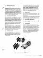
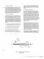
Performance Inspection
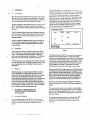
The RC Series Fabry-Perots are designed with particular
emphasis on freedom from angular and axial cavity drift with
time:: anu temperdture. See Figure 1. The mainframe is
designed with three-fold rotational symmetry (the symmetry
of an equilateral triangle) about the axis normal to the mirror
plane. This necessitates that the PZT drive elements and
Super-Invar rods be located at 1200 • This design approach
helps assure the maintenance of mirror parallelism over long
periods of time. The Super·lnvar adjustment screws are
located at 90 0 for orthogonal adjustment, but vertic;!1
A word about Burleigh's Quality Control. Every effort is
extended to insure that the instrument shipped to you works
according to specification. It is very expensive to have a
symmetry is still maintained.
defe(;tive innrume::nL re::turneu tu the fac-tury and to have an
unhappy customer.
Figure 1. RC Series Fabry-Perots. RC-170 not Shown
'.,
- 2- '
,-- 2)
4)
Choice of Materials
Each of our Fabry-Perots use Super-Invar, Invar, low thermal
expansion ceramic insulators and low thermal expansion PZT
material in a reentrant design to control the spacing of the
mirrors in the Fabry-Perot cavity. Every mechanical part
directly affecting the thermal stability of the RC-11 0 (·170,
•140, .150) is machined of Super·lnvar (a <;; 0.36 x 10·6/ oC)
or Invar (a 1.6 x 1O-6/ oC). This includes sleeves, drive plates,
mirror holders, adjustment screws and rods. In fact, because
the design is reentrant there may be zero axial drift at some
Wlvily lIpd.c.ing. Abo, by judicious placement of thin metal
washers, it is sometimes possible to make the axial drift zero
at a selected cavity spacing. For optimum performance the
environment shOUld be thermally very uniform and slowly
changing.
The RC-11 0 and RC-170 are made almost completely of
Super-Invar. The u..e ohimilar materials throughout, added
to the extremely low thermal expansion of the Super-Invar,
means optimum thermal stability. The added mass of the
Super·lnvar also helps insure mechanical stability.
The RC 140 and RC·1S0 use Super-I nvar and regular invar for
mechanical parts directly affecting the cavity spacing. Alumi·
num is used elsewhere. Alumi num is a proper choice because
of its excellent thermal diffusivity. Thermal gradients are
rapidly diffused throughout the instrument body to inhibit
,.,,-... misalignment found in interferometers using iron or other
f
similar materials. Since the aluminum is not used where it can
influence the cavity spacing, thermal performance is maintained.
3)
PZT Material
All Burleigh Fabry-Perot Interferometers use matched sets of
PZT elements to provide electrical parallelism adjustment of
the interferometer eavity as well as electrical scanning over its
free spectral range. The PZT elements are constructed from
interferometrically matched PZT discs. The PZT material used
for scanning offers the best linearity and hysteresis characteristics; less than 1% inter-order linearity and 1/2% hysteresis.
With the Programmable Ramp feature of Burleigh electronics
the scan linearity can be reduced to <; 0.1%. A high sensitivity
material is used for a large alignment range.
(r-..
There are three reasons PZT discs are used instead of PZT
cylinders. The first is discs have a lower cOefficient of thermal
expansion than c;ylinderli. This greatly improves the thermal
stability of the Fabry-Perot. The second reason is discs have
a higher "d", or piezoelectric coefficient, than PZT cylinders.
This allows a shorter PZT drive, further improving thermal
stability. The compactness also minimizes cantilevering of
the drive mirror and strengthens the assembly. The third
reason is that discs ensure a more rigid mechanical construction. Discs have a larger surface area in the direction of
expansion and more closely approach a solid member. Disc
assemblies are therefore less prone to resonances when driven
at high frequency.
.
:.
Adjustment Screws
The all Super-Invar adjustment screws used in the Fabry-Perots
have very high resolution capability with greater than 10mm ""
adjustment range. This is necessary for precisely setting the
~,\
mirror spacing and alignment for final mechanical alignment of
the mirror cavity•
The adjustment screw assembly uses 250jlm/turn metric threads
with Scm diameter Delrin knobs for improved resolution and
metric readout. Adjustments to 1/10jlm are easily made.
With the scale and dial, the 5crew position can be read to Sum
and interpolated if necessary.
There are two other advantages to the Super-Invar screws
which are not realized with other types of screws. One
advantage is the inherently reduced sensitivity of the interferometer cavity to thermal perturbations. Beside the advantages
of the Super-Invar with its lower absolute thermal expansion,
there is the advantage offered by using metal from the same
batch to make each set of screws. Different batches of the
same metal can have varying coefficients of thermal expansion,
a serious problem in screws made witn.hlgh-expansion maler iall>.
These differences are less important in the Burleigh screws
because they are made of Super-I nvar instead of some other
material with a larger thermal expansion.
The second advantage is that the thread engagement of each of
the screws is always closely matched. For instruments using a
differential screw adjustment, it may be necessary to make
significant adjustments to the differential screws in the process
of mechanically aligning the mirrors. The threads will not be )engaged identically for all three differential screws, meaning
expansion of each screw shaft is controlled from a different
point. This can introduce angular drift in the instrument due
. to temperature changes. This problem can be significant in
steel differential5crews.
5)
AsS'embly
All Burleigh interferometers are designed with hard connections
between mechanical and piezoelectric parts. There are no soft
plastic materials, compliant joints or RlV·like substances to
creep and move: these are major causes of misalignment and
drift problems in Fabry-Perots.
6)
Model RC-11 0 and RC·170 Fabry.Perots
The RellO and RC-170 are general purpose, scanning FabryPerot interferome19~s with superior thermal and mechanical
stability. They ar~ constructed almost completely of SuperInvar. The end plates, rodli, lileeves, mirror mounts, and even
the adjustment screws are Super-I nvar. The thermal expansion
of Super-Invar is <; 0.36 x 1o-6/OC, about 5 times lower than
regular invar (a -1.6 x 10⁻⁶/OC). For comparison, stainless
steel has an a = 9.6 x 10⁻⁶/OC and brass has an 6' = 11.4 x
1O-6/ oC. Low thermal expansion means stability is maximized.
- 3 The RC-" 0 and RC-170 are piezoelectrically scanned using
three PZT elements operated in parallel and made from
Burleigh's low hysteresis, low expansion, high linearity PZT
material. The PZT stacks are interferometrically measured and
matched for tilt-free scanning. Alignment is accomplished with
three high sensitivity elements for a large adjustment range.
The mirror spacing of the RC-ll 0 is continuously variable
from 0 to 150m m and the RC-170 from 0 to 11 Omm. This
allows an optimum compromise between free spectral range
and resolution. Split tube clamps lock the moveable mirror
support plate firmly in place after the gross cavity spacing
is set. The split tube clamps are precision honed Super-Invar
deeve5. The5e 51eeves have a 1.5:1 length to diameter ratio
to allow the spider to slide smoothly along the precision
ground Super-Invar rods without marring or binding. The
Re-l10 provides up to a 50.8mm clear aperture and is
compatible with standard Burleigh Mirror Sets which allow
a maximum 50.8mm clear aperture (flatness guaranteed
over 800h of the aperture). The RC-170 has a 70mm
aperture and accepts RC-690 Mirror Sets (flatness guaranteed
;"
over 800h of the aperture).
There are a number of convenience features too. For
instanee, the cavity length scale reads to 0.1 mm. The SuperInvar adjustment screws let you precisely change the cavity
spacing by less than l#m. The screws are metric. And the
convenient dial can be read to 5#m. The exposed SuperInvar parts of the RC-110 are chrome plated.
The PZT drives are constructed of laminated PZT discs
connected electrically in parallel. A thin wafer of rigid, low
thermal expansion Alumino-Silicate ceramic is laminated to
each end of the stack to provide electrical isolation. The
PZT stack assemblies are bonded between lnvar plates to
form an integral PZT drive assembly. Aluminum shields
prevent accidental touching of the PZT stacks which have
up to l000v applied. This construction technique produces
a thermally compensated assembly of minimum length,
maximum sensitivity and rigidity. It also allows easy interchangeability between PZT assemblies.
Mounting
Holes
Spring ring
7) Model RC-l40 Fabry-Perot
The mechanical configuration of the RC-l40 is identical to
the RC-11 O. The only difference is the materials used in
the construction. The end plates and spider are made of
aluminum instead of Super-Invar. Care is taken to define
thermal' expansion reference planes wherever Super-Invar
parts are attached to the aluminum support members. This
insures that the expansion of the aluminum does not affect
stability. Aluminum has good thermal diffusivity to
minimize the effects of thermal gradients.
8) Model RC-150 Fabry-Perot
The model RC·150 is especially designed for those who do
. not need large cavity separations. The RC·1S0 is similar to
the RC·l40 in mechanical construction. The difference is
in the cavity separation scheme employed. The RC-150
uses Super-Invar spacers to determine the cavity spacing
instead of continuously varying the spacing by sliding one
mirror mount relative to the other. The gross cavity
separation ot the RC-150 can be changed discretely using
the optional Super-Invar spacers. The optional spacer set
permits cavity spacings from 1 to Scm in increments of 1cm.
For cavity separations between the fixed values above, the
fixed mirror mount can be translated ± O.Scm by adjusting
the three adjustment screws.
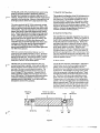
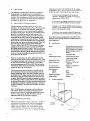
B. Mirror Holders
Two of the most important considerations in Fabry-Perot
Interferometry are the mechanical rigidity and thermal
stability in the mounting of "Aj200 plates or mirrors.
Mounting must be accomplished without stressing or distort·
ing the mirrors. With Burleigh's mounting method, three
Invar tabs are epoxied to the edge of each mirror. These
tabs have glass spheres secured into holes bored into each
tab. The mirror, with tabs, is then placed into an invar
holder with three small hardened V-groove pads at 1200 •
The glass spheres sit in these grooves, and a spring load is
applied to the top of the glass spheres to hold them firmly
against the grooved pads. Thus the mirror position is well
defined mechanically and thermally with no forces which
can stress or distort the mirrors. See Figures 2 and 3. All
RC Series Mirror Sets are mounted with this technique.
Mirror 1st su rface
protrudes about 0.1 mm
Mirror
V-pad
Invar
tab
Figure 2
Invar
Mirror Cell
Glass
ball
- 4 -
Figure 3. Burleigh Fabry.Perot Plate Mounting Technique
Each mounted mirror is then secured in the interferometer
with three screws. The advantages of this method are: the
mirror )urfac;e is precisely referenced to the invar ring, ,uch
that when the invar rings of both mirrors of the cavity
touch, the mirrors can protrude slightly from their holders
to allow for very small mirror spacings. The method results
in a design which is well constrained for rigidity and does
not distort the mirror surfaces.
All elements of the collimator are mounted in one tube.
The RC41·1 Mounting Bracket is recommended. This
brat;ket positions the collimator at the correcit optical axis
height for the RC- 1.1 0, RC·170, RC-140 o(RC, 150.
C. Ramp Generators
F. Thermatrol and Thermal Box
The Burleigh RC43 or RCM Programmable Ramp
Generators are designed to operate with the RC·ll 0, RC·170,
RC·140 or RC-150 Fabry.Perots. Consult the separate
instruction manual for operation.
The RC·7S Thermatrol tm is an insulated, temperature
controlled enclosure for all Fabry·Perots. It maintains the
temperature to <; O.OSOC. The RC-34 Thermal Box is a passive
enclosure; it is an RC·7S without temperature control and
has W' polyurethane insulation inside a walnut stained box.
The windows are removable.
D. DAS Stabilization Systems
OAS·l and DAS-l0 Data Acquisition/Stabilization Systems
authomatically correct for cavity drift and misalignment of
the Fabry·Perot. Refer to the Fabry-Perot c;atalog for
further detail.
E. Collimator and Mounting Brackets
,..........
Some imaging system must be used to collect the light at a
pinhole. The RC4l Collimator uses a 48mm aperture
achromatic lens of a nominal 2S0mm focal length and a set'
of x-y positionable pinholes for this purpose. Interchange·
able pinholes of 50, 100, 200, SOOJ.lm are easily screwed
into the x,y slide. Two micrometer heads provide precise
adjustment of the pinhole location at the focal point of the
lens. The pinholes are precision laser-drilled and mounted
in holder.;.
G. Composite Kinematic Mounting Base
The RC-24 Composite Kinematic Mounting base provides
8, tP and 1/1 angular adjustment as well as vertical positioning
for all Fabry·Perots.' Super·lnvar is used to reference the
end plates and ~he positioning is kinematic for stress·free
mounting and precise repositioning on the optical axis. The
RC·24 can be ordered mounted in the RC-34 or the RC·7S
or it can be used freestanding.
~)
,
'.
, I. Multipass Options
3. OPERATION
The RC·22 Multipass Option allows 3·pass or 5·pass
operation of the RC·ll 0 or RC·l40 Fabry·Perots with any
Mirror Set. The apertures in 3 or 5 pass are 11 mm or 5mm
respectively. The RC-27 allows 3-pass or 5-pass operation of
the RC-170 with a RC-690 Mirror Set and provides apertures
of 15mm or 9mm respectively. Consult the Fabry-Perot
catalog and the Multipass Option Tech Memo for more
,
detail;
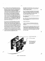
A. RC·11 0, RC·170 or RC·140 Fabry-Perot
To set up the RC-11 0, RC·170 or RC·l40 for operation,
consult Figure 4a, Figure 4b and the following directions:
Rear Plate
Split Tube Clamp
Movable Plate
Cavity Length Scale
Super·lnvar Rods
PZT Drive Assembly
Adjustment Screws
Centering Screw
Adjustable Plate
(i~
, \
Figure 4a. RC-140 Fabry·Perot. RC·l10 similar but
constructed entirely of Super·lnvar
Figure 4b. RC~ 170 with RC·27 Multipass Option
'.,
- '6 -
, - . (1) Carefully remove the cardboard and tape around the
plate controlled by the screws. Note that this screw plate is
held off the end plate by three screws. Carefully extend
the adjustment screws until they seat in the sapphire
V·blocks and move the screw plate off the end plate. Now
the three screws in the screw plate can be removed. The
cavity spacing is read with the cavity scale. There is no
direct correlation to scales and dials on the adjustment
screws, although they can be used if they are calibrated.
The scale is zeroed at the factory lor a typical set of mirror
holders, Standard factory setting allows the cavity to be
read to an accuracy of 0.1 mm due to machining tolerances
and mounting errors. If a spacing accuracy of greater than
about 0.1 mm is required, the adjustment screw scales and
dials should be calibrated with the mirrors in place. The
scale can then be read to SlJ.m
(2) Loosen the three split tube clamps on the moveable
support plate that rides along the three Super-Invar rods.
Slide the moveable support plate to the end opposite the
other mirror mount. Tighten the clamps. Stand the instrument on each end and insert the RC-600 Series mirrors into
your Fabry-Perot with the screws provided, The mirrors are
mounted in speciallnvar holders. The Fabry-Perot plates
have a wedge angle of 10·15 arc-min. The point of maximum
thickness is marked by an arrow scribed onto the edge of
each plate (note: this arrow also points to the first surface).
The plates should be mounted in the Fabry-Perot such that
V-- the arrows on each plate are 1800 apart in order to minimize
angular beam deviation through the Fabry-Perol.
Be careful not to pinch the cable. Also when placing the
Fabry-Perot on end make sure the micrometers do not
damage the sapphire V-blocks.
):
(3) Set the desired mirror spacing. The mirror spacing is
given by: the O·150mm scale reading minus the 0-1 Omm
reading on the large knobs. The accuracy is about O.lmm;
for a more accurate indication the 5pdl.ing must be
accurately measured for each mirror set.
(4) The RC-41 Collimator can be attached to the RC·41-1
Mounting Brackets.
(5) Connect the 10 foot cable to the Ramp Generator or
DAS. The connector contains seven leads for bias, ramp
functions and ground.
'
B. RC·150 Fabry-Perot
In general, operation of the RC-150 is the same as the
operation of the RC·140, with the following exceptions.
See Figure 5.
Gross cavity separation is governed by Super·lnvar spacers.
These spacers are of specified lengths in 10mm increments.
The RC'150 does not have a cavity scale so the spacing
must be measured. The adjustment screws can be calibrated
and used to set and read the cavity spacing to 5IJ.m within
their 10mm range.
)
Super-Invar Spacer Rods
PZT Drive Assembly
RC·150 uses same front
plate with adjustment
screws "and adjustable
plate as RC·140
J
Figure 5. RC-150 Fabry-Perot
- 7 1)
2}
Making the mirrors parallel.
Making the pinhole of the collimator coincident with
the central spot of the Fabry-Perot fringe pattern.
The formal operation usually proceeds in three steps:
1} An initial rough adjustment using the adjusting screws.
2) A fine adjustment using the adjustment screws.
3) A super-fine adjust using the PZT stacks. For
convenience, the mirror adjusted by the adjustment
C. General
The PZT stacks have Alumino-Silicate end insulators and
are epoxied to the plates of the PZT drive assembly. This
package is attached to the Fabry-Perot with three screws.
It is easily removed or changed, if an infrared PZT drive is
required, for example.
4. SET.UP AND ALIGNMENT IN THE VISIBLE,
screws shall be referred to as A, and the mirror adjusted
by the PZT drive assembly as B.
UV AND NEAR IR
A. Preliminary Discussion
Aligning of the interferometer is most easily accomplished
by using a small cw laser {e.g. He-Ne laser} as the source.
Although such a source is not absolutely necessary for small
plate separations, it becomes increasingly vital for rapid and
easy adjustment as the plate separation becomes large
{d=lcm}. It is not necessary that the laser wavelength
wrn:spond to the reflectivity peak of the mirror coatings;
even 2()O;6 reflectivity at the laser wavelength is adequate.
Mirrors for the visible, UV and near IR can normally be
aligned with this technique if the substrates are transparent
to the gas laser wavelength. Alignment consists of two
major operations:
Laser
I
\.
At this point connect the Ramp Generator as described in
Its operating manual. Bias controls should be set to mid·
position. The ramp should be turned off and each pot in
the Slope Trim Section turned fully counterclockwise. The
power light should be on.
B.
Rough Adjustment
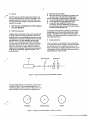
First, it is necessary to make the laser beam perpendicular
to the mirror B, as shown in Figure 6. The laser should be
sent through a hole in a card approximately 1mm in diameter. By adjusting the angular position of the laser or the
interterometer, the beam reflected from B can be made to
pass directly back through the hole.
Card with Hole
Fabry-Perot
~P~).---+--/--+-+--f--t--e----Figure 5. Alignment of Fabry-Perot Perpendicular to l3eam
The transmitted beams are now viewed on a distant screen,
as shown in Figure 7. By adjusting the angular tilt of A
with the adjustment screws, the spots on the screen may be
made coincident. This completes the rough adjustment.
·
O o
....
Misaligned
Partially Aligned'
o
Aligned
figure 7. Alignmeljlt with Small Diameter Vbiblt: Laser Beam
'"
...
• IS -
C. Fine Adjustment
,,,,.-...
At this point two techniques can be used.
If the Fabry-Perot is illuminated with a large, collimated
laser beam, several straight line fringes will be observed on
a white card at the output. See Figure 8. The plate separation increases by ),J2 for each fringe observed. Thus if six
fringes are observed, the plates will be tilted by 6 x ),J2 =
3X across the diameter of the beam. Using the adjustment
",rews and PZT's if desired, the plate alignment ean be
improved until there are no fringes' in the field. Perfect
alignment will result when the cavity is tuned with the PZT's
to transmit the source wavelength and the observed light
field is symmetrically illuminated. See Figure 9. If a
collimated source is not available, the laser beam can be
used. Rearrange the light source, as shown in Figure 10.
Diverge the laser on to a white card with a spot size approxi·
mately equal to the plate diameter. It should now be
possible to see fringes by looking in at the B mirror side,
Figure 8. Alignment with Large CoJlimated Beam.
Misaligned by Three Fringes
again as shown in Figure 9. Since the pupil of the eye is
only a few mm in diameter, it sees only "local" fringes
generated by a corresponding small cross section of the
mirrors. By moving the head up and down or sideways,
'
the fringes will be seen to expand or contract, unless the
,,' )
mirrors are already aligned perfectly. An opening up of the
rings means that the plate separation is increasing, and a
closing down means that the separation is decreasing.
If the central fringe is almost collapsed, this technique is
extremely sensitive. Thus one can tell immediately which
way the mirror!> mucot he tilted about an axis perpendicular
to the head movement in order to improve mirror parallelism.
By adjusting each of the two orthogonal adjustment screws,
and by repeating the sequence several times, the mirrors can
be brought intu nearly perfect parallelism very rapidly. The
operation will proceed most rapidly if the head motion is
always perpendicular to the two orthogonal axes about
which the adjustment screw in question rotates the mirror.
•
Figure 9. Alignment with Large Collimated Beam.
Perfect Alignment with Fabry-Perot Tuned
to Input Wavelength
~----8-B---}>1
FP
Eye
/.
Figure 10. Viewing fabry-Perot Circular Fringes
with Eye
))
- 9 -
best section of the mirror. Burleigh Fabry-Perot plates
normally have a slight spherical deviation from perfect
flatness. Burleigh tests all mirror sets for flatness before
shipping.
D. Super·fine Adjustment
Upon completion of alignment with the adjustment screws,
final parallelism adjustment may be made with the bias
controls using the method of section 4C to check parallelism.
I f for optimal alignment one of the bias controls is near the
end of its scale, it is a good idea to adjust the corresponding
adjustment screw, so that all bias controls are returned to
approximately mid·scale. This will allow for maximum
flexibility in making future electrical adjustments.
F. Adjustment of the Collimator
The focus of the collimator lens must first be adjusted.
This is accomplished before the collimator is attached to
its base. Screw the pinhole device containing the eyepiece
lem into the X-Y slide. Note that this device contains a
rather large hole approximately 3mm in diameter in lieu of
an actual pinhole. Adjust the eyepiece lens until the edge
of this hole is seen clearly in sharp focus. The edge of the
hole is in exactly the same pOSition along the axis ot the
objective lens as that of the actual pinholes. Now look at a
very distant object through an open window, and adjust the
collimator objective lens until the image of the distant object
seems to be suspended in space at the plane of the hole.
Focusing is now complete, and the collimator may be
attached to its base.
E. Survey of Mirror Flatness
After the adjustments of sections 4C and 40 h;:we neen
carried as far as possible, it may be noted that the ring dia·
meter cannot be kept constant over the whole surface of
the plates. That is, unless the mirror flatness is perfect, one
can usually find mutually "high" or "low" spots on the
mirrors. When the central ring is nearly collapsed, the ring
diameter will be extremely sensitive to plate errors since the
ring diameter is a cosine function. If such deviations seem
excessive, they are probably due to one of the following
causes:
1)
With the Fabry-Perot illuminated as in Figure 11, view the
ring pattern through the eyepiece lens of the collimator.
The mirrors may not have been properly mounted, i.e.,
Adjust the lateral position of the eyepiece with the two
the mounting has induced strain in the mirror blank.
4) The coating may have stressed the substrate.
micrometer screws, such that the ring pattern is exactly
concentric with the large hole. The eyepiece may now be
unscrewed and replaced with the working pinhole. The
pinholes have been accurately machined so that they will
be close to the exact center of the large hole on the x-y
slide. Thus, the working pinhole will now be within about
25J.(m of the correct position.
One can often improve the finesse of an instrument by
using a smaller aperture to limit the incoming beam to the
USE CAUTION WHEN VIEWING THE BEAM TO AVOID
EYE DAMAGE;THE INTENSITY OF THE BEAM
2) The mirror blanks may not be up to specification.
3) The coating may not be as flat as the substrate.
.'
'
SHOULD BE ATTENUATED AS MUCH AS POSSIDLE •
Collimator
Card
Fabry·Perot
Lens
Eyepiece
Figure 11. Viewing Fabry-Perot Circular Fringes
through Collimator
.
,.
....
• 10 G. Final Adjustment
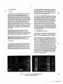
1)
Finesse
As a check on the overall alignment of the Fabry-Perot, and
to make any final touch-up adjustments that may be
necessary, one.should observe instrument finesse in the
electronically scanned mode. That is, with a photomulti·
plier or photodiode located behind the pinhole, the output
of the detector should be connected to the vertical amplifier
of a scope. The horizontal amplifier should be driven with
either the output + 100 from the Ramp Generator or the
time base of the scope by triggering it with the trigger
output of the Ramp Generator., .The spectrum of a cw laser
should then appear as a series of sharp peaks on the screen.
See Figure 12. (A scan time of 50ms to lOOms provides a
nearly flicker free presentation on the scope screen that is
. easy to view).
Small pinholes can be precisely centered on the fringe
pattern by adjusting each micrometer screw on the x·y
pinhole slide such that the fringes move in one direction (e.g.
always to the left) as a micrometer is advanced or retracted
from the c;cnter of the fringe pattern. See Figure 13.
Also it may be possible to sharpen up a laser line by making·
slight adjustments of the transducer bias controls. The
optimum mirror parallelism can be achieved this way.
2) Slope Trim
In a Fabry-Perot Interferometer, if the three piezoelectric
scanning elements have slightly different sensitivities tilting
during scanning will resulL The amplitude of the fringe
pattern in each free spectral range will change as the t- abry·
Perot scans through several free spectral ranges indicating
less than optimum alignment at some point during the scan.
::'
If you observe this effect, the slope trim controls can be
used to compensate for the differential sensitivities of the
piezoelectric elements. It is very convenient to use the
three bias controls to determine the relative sensitivity of
the stacks before making this adjustment.
. ).
To do this, turn the SLOPE TRIM controls approximately
~ turn clockwise. Use the ALIGNMENT controls to align
the Fabry·Perot optimally for the first order in the scan.
The amplitude 9f the subsequent orders will decrease.
Observe the last order and bring it into optimum alignment
with the ALIGNMENT controls. Note which control or
controls are lIsed to make this adjw;tment. Reset the
controls to align the first order. Now adjust the SLOPE
TRIM control or controls corresponding with the controls
noted above such that all orders have the same amplitude.
After repeatin~ this procedure a few times all spectral orders
should have approximately equal intensity indicating the
PZT scan is free of tilL
5. ALIGNMENT IN THE IR
If the substrates are not transparent to the visible, alignment
is more difficult. If a laser source is: available, however,
alignment can be accomplished without undue difficulty.
First, by measuring the actual plate positions relative to
each other, the plates should be aligned to about 0.001" to
0.002". Now, if this Fabry-Perot were to be illuminated
with a large, collimated beam, and if the output could be
viewed, ten or fewer straight-line fringes would be observed
{at A= 10.6J,Lm).This fringe pattern can be effectively
determined by illuminating the Fabry-Perot with a small
laser beam, traversing the beam across the plates in X and
V, or traversing the Fabry-Perot itself, collecting the through-
put with a lens and plotting the detector output. Thus the
effective fringe pattern, and therefore plate alignment, can
be determined. By changing the alignment and repeating
the process, the Fabry-Perot alignment can be improved
until the transmission is symmetric over the plates when
tuned to the source wavelength.
.,'
Figure 12. Fabry-Perot in Scanning Mode Showing Partial
Alignment and Perfect Alignment
JJ
- 11 -
Pinhole to Left
Pinhole to Right
Pinhole Centered
Figure 13. Fringe Position as a Function of Pinhole
6. OPERATIONAL HINTS
There are, of course, methods of operating the RC·11 0,
RC-170, RC·140 or RC-1S0 that you'll develop through use
of the interferometers. Here are some areas that you should
watch, however.
.
A. Operation of the interferometer in an isothermal
environment will improve the performance of the interferometer. Burleigh's RC-7S Thermatrol Enclosure or RC·34 or
RC-35 Thermal Box is recommended.
B. The adjustment screws are lubricated with a specially
"..-... selected lubricant which provides optimum stability. None·
('
theless, one should allow a period of time for the lubricant
'- ~. to displace from between the threads and the instrument to '
equilibrate after an adjustment is made.
Posi~ion
C. If a Ramp Generator is being used, there are some
points to consider:
1) The 20 and 50 millisecond ramp rate should be
employed only for alignment and cursory spectral analysis.
2) The ramp waveform is rounded at the initiation and
end of the ramp. The purpose is to minimize oscillation
of the driving mirror from mechanical resonance effects
caused by the rapid change in ramp voltage during retrace.
3) The rounding on the ramp waveform is a constant and
at ramp rates longer than 20 milliseconds it is a negligible
contribution to scan non·linearity.
4) For IR PZT drives it may be necessary to operate at
ramp durations of 200ms to 1s to obtain optimum linearity.
- 12 D. There may be a slight "stiff" feel to the Adjustment
Screws. To maintain the best stability, lubricants must be
kept to a minimum and the spring loading force must be
large. With a small amount of lubricant and strong springs
the screw threads will feel "stiff". Better "feel" will result
from a lighter spring load but stability might be reduced.
An optimum compromise must be determined experi·
mentally.
How to Determine
Cause:
To ensure an adequate spring force for holding the screw
plate against the adjustment screws, the springs should be
extended approximately one·half inch or more.
Retract adjustment screws and
remove springs so adjustable plate
may be removed. Inspect sapphire
V·blocks with magnifying glass.
Small localized fractures or a
major fracture can be caused by
allowing the adjustable plate to
"snap" into position against the
adjustment screws when the
E. The sapphire V-blocks that mate to the tungsten carbide
ball ends of the adjustment screws are very hard and can
easily be damaged by a sharp tap or allowing the adjustable
plate to fall against the screws. The Fabry·Perot should
therefore be handled carefully at all times.
7. TROUBLESHOOTING
A. Symptom:
No Scanning of cavity
Possible Cause:
Electronic controller not connected
Electronic controller malfunction
No incident electromagnetic
radiation
Wrong mirrors for incident radiation
Detector malfunction
How to Determine
Cause
B. Symptom:
Check "all connections
See separate electronic instruction
manual
Recheck coatinl!. curve
Check detector operation
Severe deterioration of finesse
across scan duration.
Possible Cause:
How to Determine
Ci:lU::.e;
Electronic controller malfunction
Poor electrical connection to one
PZT stack
Mechanical separation of PZT discs
Separation of PZT stack assembly
from invar support plates
Incorrect Slope Trim setting
Check all connections for electrical
continuity
Check PZT assembly for broken or
separated elements
Slope Trim
C. Symptom:
Instrument doesn't hold alignment
Possible Cause:
Fractured sapphire V·blocks
Clamps not tight on Super·1 nvar rods
Dirt or other particulate matter
between mirror holder and
support plate
Mirror holders loose in support
plates
Mirrors loose in holders or tab loose
on mirror
Broken or loose PZT stacks
Check all screw connections
Gently press on PZT assembly at
location of each stack while
scanning. Fringes should return t~
original peak height when pressun. ~
is removed. If not, problem may
be there. Remove mirror holders
and clean mirror support plate.
Recheck as above.
~pdllgs
dIe ill pldce. I f fractures
are observed the V·blocks must be
removed and replaced or removed
and re-epoxied into the plate so
only good surfaces are exposed.
Make certain no epoxy remains on
surfaces of V·blocks.
('"
8. SPECIFICATIONS
Fabry·Perots
Type
RC·ll 0, RC-170
RC.140, RC.150
Aperture
RC·ll 0, ·140, ·150
RC·170
Scan Method
RC·11 0, RC·140, RC·170, RC·1 SO
All Super·lnvar construction
Aillminllm, Surer.1 nvar and Invar
)
50mm
70mm
Thermally compensated dual PZT
assembly, 1.25pm scan, (6pm in IR
models), 1.75pm alignment
Mirror Separation
0·150mm
RC·110, ·140
0·1 Omm; O·50mm with spacers
RC·150
0·110mm
RC·170
Linearity with Burleigh
~0.1%
Electronics
<; 1% over hIm
PZT Linearity
<; 1% over 1pm
Scan Hysteresis
Adjustments
movable mirror mount manual sliding to set gross cavity
spacing: PZT alignment to 'A/500
precision, range 1.7 Spm
Super·lnvar screws 250pm/turn,
fixed mirror mount
A/25 alignment sensitivity with
2" delrin knobs
Read Outs
Scale and vernier reads to .1 mm:
cavity spacing
0.02mm if calibrated
,)
screws
dials read to Spm
depends on mirrors
Finesse
see performdnce sel;tion
Performam;e
- 13 -
1
Fabry-Perot Mirrors
Material
RC-600 Series
RC-800 Series
Flatness @A= S50nm
surface 1
surface 2
Holder
Coating
RC-600 Series, RC-800 Series
Fused Silica
ZnSe
All 00 or "'1200
A/10
Invar
high reflectance, multi-layer
dielectric on surface 1i AR on
surface 2
Wedge
•
I
RC-600 Series
':;';;'10'
RC-800 Series
>3'
Collimator
RC-41
Construction
Length
Pinholes
Adjustments
Lens Focal Length
Mounting
Aluminum
275mm nominal
SO, 100, 200, 500pm
orthogonal micrometer adjust of
pinhole location
254mm (visible models only)
Three 10-32 clearance holes located
on a 4.5" dia. bolt circle. Affixes to
RC-41·1 mounting brackets. RC·41·1
affixes collimator to work bench
with four ~·20 screws on a 4"
square hole patt~rn
Multipass Option
RC·22, RC·27
Type
Aperture
RC·22,3 pass
RC-22, 5 pass
RC-27, 3 pass
RC·27,5 pass
X-Yadjustment
Corner cube quality
Entrant surface coating
Housing and masks
Coupled corner cubes
Mounting Bases
RC·24
Type
Vertical adjust
Elevation adjust
Azimuth adjust
Length standard
Composite, kinematic
1.Scm
Thermal Box
RC-34
Size
Insulation
19" x 10" x 10Vl"
Vl" polyurethane, Super-Insulation
-lConsu~_ct_io_n
Thermatrol tm Enclosure
RC-75
Size
Insulation
Yl" to 1" polyurethane, alumized
Construction
Temperature Stability
Ambient Range
Burleigh Fabry-Perots are warranted against defects in
material and workmanship for a period of one year after
date of delivery and the return of Burleigh's warranty card.
During the warranty period, Burleigh will repair or at its
option, replace parts which prove to be defective when the
instrument is returned prepaid to Burleigh Instruments, Inc.
Before return of an instrument always call Burleigh for
approval of the return. The warranty will not apply if the
in ..turment has been damaged by accident. misuse. or as a
result of modification by persons other than Burleigh
personnel.
30
30
Super-I nvar
s_=-----------
~_l'_'
Mylar "Super-Insulation"
W' stained birch
";0.050 C
220 ± 30(:
9. WARRANry
11mm
6mm
15mm
9mm
± 1/16"
5-10 sec.
Multi-layer AR for REt;; 0.5%
Black anodized aluminum
_ _ _ _ _......
19" x 10" x lOW'
\
)
- 14 -
10. OUTLINE DIMENSIONS
RC·II0,14O
J""-------302
1'""19'
:7l
f50.8
51
C.A.-
,
All dimensions in mm
,
1--127---1
L
RC·170 =2·56 tap
=~.28Tapped..J
4 Places
(Attach at one end only)
3places@
1200 on 88.9
B.C.
buleig,
Burleigh Instruments, Inc.
Burleigh Park
Fishers, NY 14453
"'---"
(716) 924-9355
Telex 97-8379
FP 26S 581
"')
Fabry-Perot Options
Instruction Manual
1. Thermatrol
2. Thermal Box
3. Mounting Base
4. Collimators
ill
~
l1li
I
..
CONTENTS
PAGE
1. General
1
A. Introduction
1
B. Unpacking
C. Warranty
1
2. RC-75/RC-77 Thermatroltm Temperature Controlled E;nclorures
1
1
A. Instrument Description
1
B. How It Works
C. How To Use The Tbennatrol Enclosures
D. Troubleshooting· Test Points
2
2
2
E. Specifications
F. Outline Dimensions
2
3. RC-34;37 Thermal Boxe:s
:2
3
A. Instrument Description
4.. RC-24 Composite Kinematic Mounting Base
A. Instrument Description
B. How It Works
1. Attaching the RC-24
2. MOWlti.ng the Fabry-Perot on the RC-24
3. Specifications
C. Specifications
D. OI.ltline Dimensions
5. RC-41/RC-47 Collimators
. A. Instrument Description
B. Adjustment of the Colllmator
C. SpedficatiODS.
D. Outline Dimensions
3
4
4
5
1.
GENERAL
The Re·7S
A.
InlroduCliun
ture of lhe- F.lbry·Pell)l In t 0.10<':. TIll.' shell is con)lruCled
of 11 nlm lhick w.llnu I slained birch. The control panel,
localeu on the top of the bl)X, consislS of two loggle switches,
three LED's anu a 1 amp slow blow fusc. See Figure 1. The
sensing 3nd control circuitry as well as the power supply is
loc3led inside under the control panel. The interior is lined
with 19mnl thick urethane for cxccUenl thermal isolation.
Heater elements are bonded to metal radiating plates which
are then attached to the insulated inner walls.
Thi~
Inmu.:tion Manual describes several popular oplions for
Burleigh'$ RC Series Fabry-Perot Interferometer. They have
been included in one manual since most customers order two
or more of thesc.item50 with their Fabry.Perot system.
The RC·75 and RC·17 Thcrmalrol Enclosures and RC-34 and
RC-37 Thermal Box!:) are u~d to hou)c the: ontire F~bry.
Perot. They insulate the systems and keep the precision optics
dust free_
The RC-24 Mounting Base, which can be mounted inside the
thermal enclosures, allows for positioning of the entire Fabry.
Perot and includes a Super-Invar reference plane as well as
kinematic support.
The RC41 and RC47 Collimators are used at the output of
the Fabry-Perot to collect the transmitted light. A series of
interchangeable pinholes control the angular extent of the
interfering rays.
8.
Unpacking
AI! Burleigh instruments are shipped in heavy duty cartons
which protect the unit during normal handling and transpor·
tation. If the outside of the shipping carton is damaged,
notify your shipping department immediately. The shipping
department may wish to notify the carrier at this point.
If the shipping carton is undamaged, the instrument should be
removed from the carton. If damage is evident visually, notify
your shipping department and Burleigh Instruments, Inc.,
immediately.
C.
Warranty
Burleigh products arc warranted against defects in material
Vld workmanship for a period of one yeM after date of
delivery with the rerurn of Burleigh's warranty card. Ouring
the warranty period, Burleigh will repair or at its option,
replace partS which prove to be defective when the instrument
is returned prepaid to Burleigh Instruments, Inc. Before
return of an instrument always call Burleigh for approval of
the return. The warranty will not apply if the instrument haS
been damaged by accident, misuse, or as a result of modifica·
tion by persons other than Burleigh personnel.
2.
Rc·1S/RC·77 THERMATROLtm
TEMPERATURE CONTROLLED
ENCLOSURES
A.
instrument Descriplion
In the following d~cription the RC-'S will be used in :111
examples. All statements, however, also apply to lhe RC-77
Thermatrol enclosure for Burleigh's 70mm Fabry.Perol . .
System.
.
rHo\'idc~ .. wdl in~ulah;!.l, !.lust· free enc;lllsurc (or
Burlei~h f,lbrY'Pl'rOIS .1tHI can be lIlIed In Cnntrllilhe tempera-
• Thermatroll RC-75
PQW(A
e('\"TAo~
nup
TIMP
ot,VUHIg,.
..
I AUPSB
"'GH
OYER
..ow
. blfleig,
~----------------------------------------~;
Figure 1
The upper portion of the RC·'S i:l rcmoved from the base by
releasing the four steel dip.latches. A cutout for feeding
through the electrical connec:tion to the Fabry-Perot is provided
on the bottom side of the upper section:' Anti·reflection coated
utility windows are also supplied with e~ch instrument. The
standard SO.8mm (76.2mm in the RC·77) diameter windows
are AR coated for the visible. These windows are easily
removed ~hould the user dc)ire to change or replace them.
The base of the RC·7S is large enough for an RC·24 Composite
Kinematic Mounting Base which permits several degrees of (J ,rp
and a adjustment, as we\las approximately 12. 7mm of vertic;aJ
adjust. These adjustments are useful for properly aligning the
entire Fabry·Perot with respect to the incoming radiation.
The RC·24 is normally mounted in the RC·7S at the fal:tOry
although it can be done in the field with little difficulty.
The RC·75 can actively control the temperature ofa FabryPerot to an accuracy of::!: O.lOC for a 60C room temperature
change.
The probe aS$embly found inside the box is to be attached to
the Fabry-Perot by way of the magnets on its side. The best
location is the side of the adjustable mirror plate. It is advanta·
geous to apply a small amount of thermal grease to the probe
to aid heal transfer.
The operating temperature: is preset to approximately 290(;
or 330C (depending on switch sctting) and will bring the
fabry-Perot to this temperature in approximately one to
two hours.
·
,
B.
How It Works
The temperature is sensed with a thermistor in
it
precision
meter be used in place of the osc;lIoscope for the voltage
measurements. NOlC; Thi) unit uses a 1 :amp slow blo ..... fuse
on the front panel. Do not ~se any other type of fuse.
,~ bridge network. The bridge signal is then amplifted and
1) With line cord unplugged theck operation of
thermistor. Resistance at 11·9 and Jt ·11 should be
approximately 2.2Kn at 250(.
compared to a sUble reference ramp generated in the control
circuitry. The zero voltage switch takes this information and
through a triac, proportions the amount of power supplied to
the heaters for re~ulation of the temperature.
C.
pin 4 of U I (LM324) should both rc.ld 6.8 ! 0.5VOC,
How To Usc The ThcrlllJtrol Enclosures
Place the magnetic thermistor probe on lhe device to be
controlled. On Burleigh model Fabry.PeroLS, the best position
for the probe is on the side of the adjustable mirror plate.
On other instruments it is b~t to exoerimentally determine
the optimal sensing point. The device to be controlled is then
placed on the wooden base and the upper portion of the
RC·7S is latched into place. Make sure any direct electrical
- connections to the Fabry·Perot are fed through the cutouL
A tightseal is very impor..ant for proper operation. The latches
line up with the top for one orientation only to avoid tedious
:system re:aJignment every time the top is removed. Check the
RC·7S for correct operating voltage which will be either
110vac or 22Ovac. Each RC-75 is wired for one of the above
voltages and should the user desire to rewire for a different
line voltage. consult Burleigh for details. Plug in the line cord.
Tum the power switch to the ON position. A LED immediately
above the power switch should light indicating that At power
is present. Consult the troubleshooting section should the unit
fail to operate in this manner.
There are twO temperature se,t points, labeled high and low,
which are selected with the control temperature switch. These
two ranges are provided so the user c:an optimize operation for
his own particular laboratory environmenL The standard
oper.uing temperatures are 330C and 290C (for high and low
respectively). Othe:- set points are available. The user should
consult the factory for further details.
Two temperature deviation LEO'$ give an indication of the
sensor temperature relative to the set point chosen with the
control temperature switch. The upper LED lights when the
temperature is O.lOC higher than the set point and the lower
one comes on when the temperature is O.lOC lower than the
set poinL Both will remain off when the temperature control·
ler is operating to within ± O.JOC of the set poinL Depending
on the mass of the object in th~ box, the set point selected and
the laboratory conditions, it generally takes one to two hours '
to achieve equilibrium, but under some conditions as much as
four hours.
Note: if the laboratory environment is well c;ontr;lled and
free of drafts. superior Fabry-Perot performance may be
obtained by not using the temperature control feature of the
Re-7S. It should always be determined which mode of
operation is best for your laboratory conditions.
O.
3) Output.at pin 7 of U1 (LM324) should swing from
ground to 5 \,olts as probe is heated and cooled (hcatin&
can be by holding probe in hand).
4) Reference rlmp at positive side of C5 should run
from 1.5 volts to 4 volts DC in an 8 to 10 sct. interval.
If any of the test points indicated above are different than
desc:ribed, contact Burleigh for further troubleshooting and
repair suggestions.
E.
Speeification~
Thermatrol enclosures are wired
at the factory for either 110 or
Z20 VAC operation. Todlange
the line voltage consult the
fattory.
Power:
Fuse:
1 amp Slow Blow
Temperature Control:
:.t 0.1 DC for a 6 0 C room
Standard Set Points:
Outer Dimensions:
290C and 33 0 C
SOSmm L x 302mm W x
323mm H
416mm Lx 223mm W x
238mm H
temperature Change
Inner Dimcn:.ions
(including urethane):
Oear Aperture:
RC·7S
RC·77
Optical Axis Height:
47mm
70mm
114.3:t 2mm
Height of feet:
9.52mm
F. - Outline Dimensions
r---- -
Troubleshooting. Test Points
The reference point for all \oltages is AC neutral. To observe
waveform .. on .10 o,>cilloscopc thc ~copc line cord m-ust be .
isol.lIed frurn c.lrth !.:fOunu_ (;\ th,,:c prong to two prong
.1dolplcr ,ervc') the llurplI"l'\_ TIl\'
\1'i'illo~l.;ope·s ~roul1d
Coln
nuw he c"nnected to AC ncutr.ll (.It !ninu) si<.lc-uf C4) oll1l.J
IIIl"
2) Wilh power on, supplies at positive side of C4 and
Iwrti 11,'11 I
W,I\'l·t""I" .. 1>,,-.\"..,1.
Ii j, ,"~\(<!'ll'rJ Ih,lI .I
mulli-
t. ............
• '''' ,ac
10 . .
J\,
,.c "I
.,-
..............
.
- 3 -
,
.~ 3.
A.
RC-34/RC-37 THERMAL BOXES
2.
!nslrument Description
The Fabry.Perot should rest on the RC-24, secured only by its
own weight. Two special ball end stainless screws provided
wi th the RC·24, should be screwed into the holes 'in the
bottom of the (ront end plate of the Fabry.Perot until they
seat. Then the Fabry-Perol is placed so that these ball end
screws scat in the bore and slot in the top of the RC·24 with
tho roar end pl:ate restina on the Super.lnvar referonee ;trip_
In the following description the RC·34 will be used in all
examples. All st.3temenlS, however, also apply to the
RC-37 Thermal Box for Burleigh's 70mm Fabry-Perot System.
RC·34 Thermal Box is identical to the RC·75 Thermalrol
except that it docs not include active temperature control.
The construction is of t tmm birch lined with 19mm urethane
in.. ul:uion_ Removable windows. AR coated for the visible.
seal the interior of the RC·34 from drafu.
The RC·34 provides a well insulated, dust·free enclosure for
Burleigh Fabry·Perou. It protects the instrument from the
effects of drafts or rapid temperature changes. The RC·24
Composite Kinematic Mounting Base can be attached inside
the RC-34 on the base section for 8. ~. a and vertical
adjustment of the Fabry-Perot. It is recommended that the
RC-24 be attached to the RC·34 at the factory, but it can be
fitted in the field with little difficulty.
Mounting the Fabry.Perot on the RC-24
CAUTION: Always remove the Fabry-Perot from the RC.24
Mounting Base before transporting the system. Unless great
care is taken not to tilt the assembly, the Fabry-Perot can slip
loose and be damaged.
C.
Specifications
Vertical adjustment •
8 tilt (about horizonul axis 1 optic axis)
~
Cl
tilt (about vertical axis 1 optic iVtis)
tilt (about horizontal axis I optic axis)
D.
Outline Dimensions
The dimensions of the RC·34 are identical to the RC·7S.
Consult the appropriate paragraphs of the RC·7S section of
this manual for tips on setting up the RC-34.
4.
RC-24 COMPOSITE KINEMATIC MOUNTING
BASE
A.
Instrumen t Description
The RC·24 is designed to provide three functions. First, it
provides three degrees of angular adjustment of the FabryPerot about three perpendicular rotation axes (8, ~ and ex)
as well as approximately 12.7mm ofvertical adjustment.
These adju:ium::nts arc nc:cC):;.ary to properly align the: axis of
the Fabry-Perot with respect to the optical axis of the system.
.r--.
_
-...
=J~=
__M'._~~_
'f--r,
fEt.J, I
,--t:.. -_._ .. _. ____T_--.,I-T-"
~_
:i
.................
Second, it provides a Super-Invar stabilized mounting reference
for the Fabry-Perot. This insures that the end plates of the
Fabry-Perot are not stressed by forces exerted by thermally
induced length changes in the Fabry·Perot support. The
Super-Invar length standard is itself mounted such that it
cannot be affected by the al.uminum top plate of the RC·24.
5.
RC-41/RC-47 COLLIMATORS
A.
Instrument Description
Third, the RC-24 provides a three point kinematic support for
the Fabry-Perot to allow removal and precise repositioning of
the Fabry-Perot. This feature can be very useful when aligning
a complex optical system. The three point mounting also
insures that the Fabry-Perot cannot be w;up/!d or str/!'i'>l!d.
Burleigh's RC-41 and RC-47 Collimators are normally used as
light collecton with RC Series Fabry·Perot Interferometers.
A large diameter, long focal length (about 250mm F.L.)
achromatic doublet is focused onto a pinhole, thus controlling
the angular extent of radiation passing through the FabryPerut whi<;h i$ in<;ide:nt on the: de:tector. Refer to the Fahry.
Perot Tech Memo for further detail on the OPtical system.
B.
How To Usc The RC-24
1.
AU.3ching the RC-24
The f{C-24 i!) securcd to the ba!)e of the RC-75 or RC-34 or to
an optical bench with four ~-20 screws in the bott.om plate of
the RC-24. The top plate is removed by carefully· detaching
the spring and lifting. Thc holes in the bottom plate CJn be
used JS .1 lempliJlc. If the RC·24 i~ being Jllached to an exist·
ing RC·34 ur RC-75 the urClh.1fl1,." in Ihe b.l~e of these
cnclo~urcs must be carefully CUI to eX.lClly fil Ilh' KC-24.
It is also recommended in high contrast systems that a
collimator be used at the input side. This will serve to eliminate radiation with an unacceptable angular extent, thus
reducing the possibility of unwanted stray light and scatter.
The aperture of the collimator is mat.ched to the usable
aperture of the Fabry-Perot optics. The RC-41, used with
50mm optics, has a 48mm aperture. The RC47 for 70mm
optics, ha~ a 68mm Jl"lcrture. The doublct can bt: prccisdy
focuscu onto the I"Ilane of the pinhole. A visible! eyelcns is
included to simplify this Jdiu~tmerlt.
A series of precision ~s.(SO, 100,200 and SOO,.,m)
muullled and cenlefC'lllft!removahlc holcJer~, ~I) 111011 the
proper diameter can Imsdilraitcd depending on the system.
micrometer driven XW_ge is used to position the pinhole.
irll:
;--
.,th collimators are ~k: with optics for the infrared or
UV • as designated by the!.uffixes ···IR" or "·UV". Inilial
'1:US and adjustment INIf1rrequire more effort. JS is normillly
~ case in non·visible slIIllUns, anu the visible cyclclls m.lY not
usable.
//bc
.
The RC41·1 Collimator'iltwnting Bracket is recommended.
This bracket will simplif,ei:ee,slancJing mounting of the
Collimator, which has .1I!!:fl:ildrical body.
8.
With the Fabry·Perot illuminated as in Figure 2, view the ring
pattern through the eyepic.;e lens of the collimator. AdjUSt
the lateral position of the eyepiece with the twu micrometer
screws, such that the ring pattern is exactly concentric witt(
the large hole. The eyepiece may now be unscrewed and
replaced with the working pinhole. The pinholes have been
accurately machined so that they will be close to the exact
center of the large hole on the X· Y slide. Thus, the workin!:
pinhole will now be within about 251lm uf the correCl J'lo!>ilion.
USE CAUTION WHEN VIEWING THE BEAM TO AVOID
EYE DAMAGE; THE INTENSITY OF THE BEAM SHOULD
. BE ATTENUATED AS MUCH AS POSSIBLE.
C.
Adjustment of thi!t&llim.ator
The focus of the collim~ lens must first be adjusted.
This is accomplished be_~ the collimator is attached to'
its base. Screw the pin~device containing the eyepiece
lens into the X-Y slide. Ittte that this device contains a
rather large hole approxBaiely 3mm in diameter in lieu of
an actual pinhole. Adju~Uhe eyepiece lens until the edge
of this hole is seen clearl,in sharp focus. lhe edge of the
hole is in exactly the S3mr:.p05ition along the axis of the
objective lens as that of 6t actual pinholes. Now look at a
very distant objC(;t thr~an open window, and adjust the
collimator objective lensamil the image of the distant object
seems to be suspended in.ace at the plane of the hole.
Focusing is now compl_and the collimator may be
attached to its base.
Specifications
Construction
Aluminum
Length
280mm nominal
Pinholes
Adjustments
50, 100, 200,500pm
Orthogonal micrometer adjust of
pinhole location
Aperture
48mm (RC-41, RC-411 R, RC-41 UV)
Lens Focal Length
Mounting
68mm (RC47, RC-47IR, RC-47UV)
254mm (visible models only)
Three 1()'32 clcaranc;c: hol~ loc;;ated
on a 4.S" dia. bolt circle. Affixes to
RC41·1 mounting brackets. RC-4t·t
affixes collimator to work bench with
four %·20 screws on a 4" square hole
pattern
Collimator
~~fl§fl§1\--;¢-~
--..-J
U==v==..v____
Fabry·Perot
..
Lens
Eyepiece
Figure 2
Viewing Fabry·Perot Circular
. Fringes through Collimator
•
Eye
,
.\
.
- 5-
'.
D.
OUllinc Dimensions
:
~
f
I
-..................
.. -
-1
lIJ
I
I.
!
•I
........
-$-
IN.
T
IE f- .
.,..
I
'.'
I
i
LJ
...
t
--!I.--- -
I
-------rlor-.::
_-
-I\
....M'",
...
1 .....
~
1.1
....._ _ _ _
~_________________
8',.
buleig,
Burleigh Instruments, Inc.
Burleigh Park
Fishers, NY 14453
(716) 924·9355
Telex 97·8379
FP2751281
\.---.-----j-~
n.. ___
---\
I.U
MJ
.
•
,