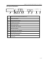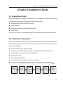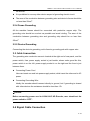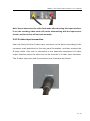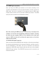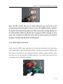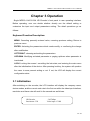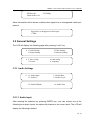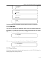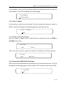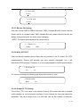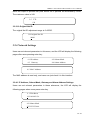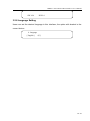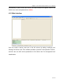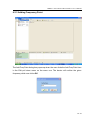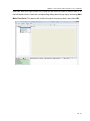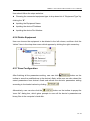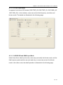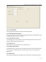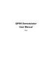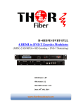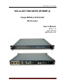
1
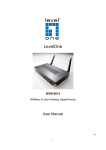
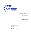
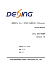
HD Encoder User’s Manual SOLA-SAT ENCODER (EHDMP-4) Single MPEG-4 AVC/H.264 HD Encoder User’s Manual Version: 1.0 Date: 2010.12.0 NMS Version: 4.01 Sola-Sat Inc. Pompano Beach, Florida 33069 Page 0 MPEG-4 AVC/H.264 HD Encoder User’s Manual TABLE OF CONTENTS CHAPTER 1 PRODUCT OUTLINE .................................................................................................. 2 1.1 OUTLINE ................................................................................................................................ 2 1.2 FEATURES ............................................................................................................................. 2 1.3 SPECIFICATIONS ................................................................................................................. 3 1.4 FUNCTION CHART .............................................................................................................. 4 1.5 APPEARANCE AND DESIGN ............................................................................................. 4 CHAPTER 2 INSTALLATION GUIDE .............................................................................................. 7 2.1 ACQUISITION CHECK ......................................................................................................... 7 2.2 INSTALLATION PREPARATION ....................................................................................... 7 2.3 CABLE CONNECTION ......................................................................................................... 9 CHAPTER 3 OPERATION .............................................................................................................. 15 3.1 INITIALIZATION ............................................................................................................... 15 3.2 GENERAL SETTINGS ....................................................................................................... 18 CHAPTER 4 NMS OPERATION .................................................................................................... 27 4.1 INSTALLATION .................................................................................................................. 27 4.2 SOFTWARE OPERATION ................................................................................................ 27 4.3 HD ENCODER OPERATION............................................................................................ 33 CHAPTER 5 TROUBLE SHOOTING ............................................................................................ 41 CHAPTER 6 PACKING LIST .......................................................................................................... 42 1 / 43 MPEG-4 AVC/H.264 HD Encoder User’s Manual Chapter 1 Product Outline 1.1 Outline Single AVC/H.264 HD Encoder is the newest broadcasting audio and video encoding device. It adopts the most advanced AVC/H.264 audio encoding algorithm, combined with advanced audio and video pre-dealing technology. This device can encode and transmit high-quality audio & video with a low bit-rate. Also, it has several analog and digital video input interfaces (CVBS, YPbPr, SDI, and HDMI), and audio input interfaces (RCA, XLR, HDMI, AES and EUB). It’s highly integrated and cost effective design gives users an excellent digital video encoding solution, allowing its wide use in DMB-T international modulator group networks, terrestrial digital TV and image monitoring etc. 1.2 Features AVC/H.264 High Profile Level 4.0 high profile level video encoding, advanced video pretreatment technology. MPEG-1 Audio Layer2 audio encoding algorithm UDP media transmission protocols & unicast/multicast output support CVBS,S-VIDEO, HD-SDI and YPbPr analog video input interfaces HDMI and SDI digital video input XLR、RCA、AES/EBU analog digital audio input PAL and NTSC SD video formats The resolution formats is 720P, 1080I etc. LCD/keyboard control method. NMS monitoring 2 / 43 MPEG-4 AVC/H.264 HD Encoder User’s Manual 1.3 Specifications Video input Audio input Resolution Encoding Video Audio Bit-rate Rate Control GOP Structure Advanced Pretreatment Encoding Sampling rate Resolution Bit-rate Stream output System function General Dimensions (W × D × H) Approx weight Temperature range Power requirement Power consumption 1 × Analog CVBS, BNC interface 1 ×S-Video Analog YPbPr input, BNC interface 1 × YPbPr video input, BNC interface HD/SD-SDI, BNC interface HDMI interface Analog stereo audio(balanced), XLR interface Analog stereo audio(unbalanced), BNC interface AES / EBU digital audio, XLR interface HD/SD-SDI embedded audio 1920×1080-60i, 1920×1080-50i, 1280×720-60p, 1280×720-50p 720×480-60i(NTSC), 720×576-50i(PAL) AVC/H.264 High Profile Level 4.0 for HD AVC/H.264 High Profile Level 3.0 for SD 0.8Mbps~20Mbps CBR/VBR IBBP De-interlacing, noise reduction, sharpening MPEG-1 Layer 2 48KHz 24-bit 64Kb/s~384Kb/s 2×ASI outputs, BNC interface SPTS over UDP, 10/100Base-T Ethernet interface (UDP unicast / multicast) LCD/keyboard operation, NMS support English control interface Ethernet software upgrade 482mm×455mm×44.5mm 8Kg 0~45℃ (Operation), -20~80℃ (Storage) AC110V±10%, 50/60Hz AC 220V±10%,50/60Hz 17.6W 3 / 43 MPEG-4 AVC/H.264 HD Encoder User’s Manual 1.4 Function Chart HDMI Audio AD Video AD HD/SD SDI Data Data Data Audio PLL Buffer Buffer Buffer Clk 27MHZ Clk 27MHZ Clk Clk Data Clk Data CLK PLL Data Bus CPU Bus FPGA Encode Module TS OUT TS Ethernet KEY/LC D ASI output Audio Buffer Audio Buffer From HDMI I2S From SDI I2S Audio Buffer From Audio AD I2S 4 / 43 MPEG-4 AVC/H.264 HD Encoder User’s Manual 1.5 Appearance and Design Front panel design: Indicator area: All the indicators will be lit when the works at current mode. Under the normal condition, the power indicator, TS Output, Encode Start and CVBS will light on. But if the signal source deteriorates, the indicator of input interface, say, the indicator of CVBS will blink. 1. LCD display screen Power:the device is working TS output:The output stream is TS SD/HD:SD/HD signal indicator Encoding Start:The device starts to encode Encoding Error:The device has encoding error 2. Indicator LED CVBS :CVBS input indicator S-VIDEO:S-VIDEO input indicator YPbPr:YPbPr input indicator HDMI:HDMI input indicator HD/SD-SDI:SDI input indicator 3. Up/Down/Left/Right Arrow 4. Enter:Confirm key 5. Menu:Menu key 6. Lock:Lock key 5 / 43 MPEG-4 AVC/H.264 HD Encoder User’s Manual Rear panel illustration: 7 8 9 10 11 12 13 7. Digital audio input interface: AES/EBU, XLR 8. CVBS input interface 9. HD/SD-SDI input interface 10. S-VIDEO input interface 11. YPbPr input interface 12. Analog audio input interface 13. HDMI input interface 14. Two same ASI output interface 15. 10M/100M Ethernet interface 16. Power switch and socket 17. Ground pole 14 15 16 17 6 / 43 MPEG-4 AVC/H.264 HD Encoder User’s Manual Chapter 2 Installation Guide 2.1 Acquisition Check When users open the package of the device, it is necessary to check items according to packing list. Normally it should include the following items: Single MPEG-4 AVC/H.264 HD Encoder User’s Manual Analog Audio/Video Composite Input Cable Power Cord If any item is missing or mismatching with the list above, please contact local dealer. 2.2 Installation Preparation When users install the device, please follow the below steps. The details of installation will be described at the rest part of this chapter. Users can also refer rear panel chart during the installation. The main contents of this chapter include: Checking the possible device missing or damage during the transportation Preparing relevant environment for installation Installing Encoder Connecting signal cables Connecting communication port (if it is necessary) 2.2.1 Device’s Installation Flow Chart is illustrated as following: Acquisition Check Fixing Device Connecting Grouding Wire and Power Cord Connecting Signal Wire Setting Parameter Running Device 7 / 43 MPEG-4 AVC/H.264 HD Encoder User’s Manual 2.2.2 Environment Requirement Item Machine Hall Space Requirement When user installs machine frame array in one machine hall, the distance between 2 rows of machine frames should be 1.2~1.5m and the distance against wall should be no less than 0.8m. Electric Isolation, Dust Free Machine Hall Floor Volume resistivity of ground anti-static material: 7 10 1X10 ~1X10 , Grounding current limiting resistance: 1M (Floor bearing should be greater than 450Kg/㎡) Environment Temperature 5~40℃(sustainable ),0~45℃(short time), Relative Humidity 20%~80% sustainable 10%~90% short time Pressure 86~105KPa Door & Window Installing rubber strip for sealing door-gaps and dual level glasses for window Wall It can be covered with wallpaper, or brightness less paint. Fire Protection Fire alarm system and extinguisher Power Requiring device power, air-conditioning power and lighting power are independent to each other. Device power requires AC power 220V 50Hz. Please carefully check before running. installing air-conditioning is recommended 2.2.3 Grounding Requirement All function modules’ good grounding is the basis of reliability and stability of devices. Also, they are the most important guarantee of lightning arresting and interference rejection. Therefore, the system must follow this rule. Coaxial cable’s outer conductor and isolation layer should keep proper electric conducting with the metal housing of device. Grounding conductor must adopt copper conductor in order to reduce high frequency impedance, and the grounding wire must be as thick and short as possible. Users should make sure the 2 ends of grounding wire well electric conducted and 8 / 43 MPEG-4 AVC/H.264 HD Encoder User’s Manual be antirust. It is prohibited to use any other device as part of grounding electric circuit The area of the conduction between grounding wire and device’s frame should be no less than 25mm2. 2.2.4 Frame Grounding All the machine frames should be connected with protective copper strip. The grounding wire should be as short as possible and avoid circling. The area of the conduction between grounding wire and grounding strip should be no less than 25mm2. 2.2.5 Device Grounding Connecting the device’s grounding rod to frame’s grounding pole with copper wire. 2.3 Cable Connection The grounding wire conductive screw is located at the right end of rear panel, and the power switch, fuse, power supply socket is just beside ,whose order goes like this, power switch is on the left ,power supply socket is on the right and the fuse is just between them. Connecting Power Cord User can insert one end into power supply socket, while insert the other end to AC power. Connecting Grounding Wire Ideally the encoder should connect directly to ground, but if grounding is shared with other devices the resistance should be less than 1Ω. Caution: Before connecting power cord to H.264/ AVC HD Encoder, user should set the power switch to “OFF”. 2.4 Signal Cable Connection 9 / 43 MPEG-4 AVC/H.264 HD Encoder User’s Manual The signal connections include the connection of input signal cable and the connection of output signal cable. The input audio & video has five choices including CVBS, S-VIDEO, YPbPr, HD/SD-SDI and HDMI. While the output TS stream has ASI and IP interfaces, and both of the two output ports have signal output. Also, user can close or open the IP output and flexibly select the interface based on their needs. The details are as follows: AV Input Wire Illustration HDMI Input connection wire illustration ASI Output Wire Illustration YPbPr input wire illustration 2.4.1 Unbalanced audio and CVBS video input connection User can firstly find the CVBS input connector on the device according to the connector mark described on the rear panel illustration, and then connect the analog CVBS video and unbalanced audio cables (in the accessories). One end is connected to the signal source equipment while the other end to the encoder’s CVBS input port. The encoder’s Analog Composite Video input port and its connection are illustrated as follow: 10 / 43 MPEG-4 AVC/H.264 HD Encoder User’s Manual Note: Users must select the video field mode after choosing this input interface, if not, the encoding video mode will not be mismatching with the input source format, and the device will not work normally. 2.4.2 S-video input connection User can firstly find the S-video input connector on the device according to the connector mark described on the rear panel illustration, and then connect the S-video cable. One end is connected to the head-end equipment’s S-video output interface while the other one to the encoder’s S -video input interface. The S-video input port and its connection are illustrated as follows: 11 / 43 MPEG-4 AVC/H.264 HD Encoder User’s Manual 2.4.3 HDMI Input connection User can firstly find HDMI input interface on the device according to the connector mark described on the rear panel illustration, and then connect the HDMI cable. One end is connected to the head-end device’s HDMI output interface while the other one to the encoder’s HDMI input interface. The HDMI input port and its connection are illustrated as follows: Note: After selecting the HDMI input port, it is unnecessary to manually set the resolution, for the device will automatically identify the resolution. Currently, the device can not recognize 1080P, so if the resolution of the video input source is 1080P, the device will not discern the signal source, so the device might not work normally. 2.4.4 HD/SD-SDI Input Connection Users can firstly find the HD/SD-SDI input interface on the device according to the connector mark described on the rear panel illustration, and then connect it with the HD/SD-SDI or ASI cables. One end is connected to the head-end equipment’s HD/SD-SDI output interface while the other one to the encoder’s HD/SD-SDI input interface. The HD/SD-SDI input port and its connection are illustrated as follows: 12 / 43 MPEG-4 AVC/H.264 HD Encoder User’s Manual Note: HD SDI and SD SDI use the same SDI input port, users can select corresponding mode through the menu on the LCD or NMS operation, and then the system will automatically detect the video format and scrolling display it on the LCD interface. While the HD SDI can not support 1080P currently, so if the input video resolution is 1080P, the device will not start encoding or switch the resolution to 1080P and will cause encoding error. 2.4.5 YPbPr Input Connection Users can find YPbPr input interface on the device according to the connector mark described on the rear panel illustration, and then connect the YPbPr cable. One end is connected to the head-end device’s YPbPr output interface while the other one to the encoder’s YPbPr input port. The YPbPr input port and its connection are illustrated as follows: 13 / 43 MPEG-4 AVC/H.264 HD Encoder User’s Manual Note: If the input video format is mismatching with the configuration video format, it will cause the device does not encode or appear some encode error. And the Y input port must be connected, otherwise, the device might not detect the input signal; and the Pr and Pb input ports must be connected to corresponding ports, otherwise, the program color might be abnormal. 2.4.6 ASI Output Interface Connection User can find ASI output interface on the device according to the sc connector mark described on the rear panel illustration, and then connect the ASI cable. One end is connected to the Encoder’s ASI output interface while the other one to the streaming multiplexer’s or modulator’s ASI input interface. The ASI output port and its connection are illustrated as follows: 14 / 43 MPEG-4 AVC/H.264 HD Encoder User’s Manual Chapter 3 Operation Single MPEG-4 AVC/H.264 HD Encoder’s front panel is user operating interface. Before operating, user can decide whether directly use the default setting or customize the input and output parameters setting. The detail operations go as follows: Keyboard Function Description: MENU: Canceling presently entered value, resuming previous setting; Return to previous menu. ENTER: Activating the parameters which needs modify, or confirming the change after modification. LEFT/RIGHT: choosing and setting the parameters. UP/DOWN: Modifying activated parameter or paging up/down when parameter is inactivated. LOCK: Locking the screen / cancelling the lock state, and entering the main menu after the initialization of the device. After pressing lock key, the system will question the users to save present setting or not. If not, the LCD will display the current configuration state. 3.1 Initialization After switching on the encoder, the LCD interface will display the company name, device modes, and the current code rate in the first row while the video input interface, resolution and frame rate will scroll in the second row as follows: HD Encoder Resolution: 576I 5.457Mbps Video input: CVBS 15 / 43 MPEG-4 AVC/H.264 HD Encoder User’s Manual HD Encoder Norm mode: PAL 5.457Mbps Alarm information will be shown as below when signal loss or unsupported video input present. Signal loss or unsupported video input: CVBS 3.2 General Settings The LCD will display the following page after pressing “Lock” key. ▶ 1 Audio Setting 3 Output Setting ▶ 5 Save config 7 Version 2 Video Setting 4. Network Setting 6 Load config 8 Language 3.2.1 Audio Settings ▶ 1.1 Audio Input 1.3 Audio Fs 1.5 Audio ESMode 1.2 Audio Rate 1.4 Audio Layer 1.6 Audio Gain 3.2.1.1 Audio Input After entering the submenu by pressing ENTER key, user can choose one of the following three audio inputs; the option with bracket is the current state. The LCD will display the following interface: 16 / 43 MPEG-4 AVC/H.264 HD Encoder User’s Manual 1/1/ means the current page 1.1 Audio Input [RCA] XLR 1/1 AES/EBU 3.2.1.2 Audio Bit-rate After entering the submenu by pressing “Enter” key, user can choose one out of the following bit-rates, the option with the bracket is the current choice. The LCD will display the following page. “1/2” means the current page. And the number at the upper and right corner is the total effective output audio bit-rate. 1.2 Audio Rate 128Kbps 19.700Mbps By pressing “Enter” key in this interface, the LCD will display the following page: 1.2 Audio Rate 64Kbps 96Kbps 1.2 Audio Rate 256Kbps [ 384Kbps] 1/2 [128Kbps] 192Kbps 2/2 3.2.1.3 Audio Fs, Audio Layer and Audio ES Mode These three items are read-only, users can not modify it. So after enter the submenu, the LCD will display the following pages: 1.3 Audio Fs [ 48 KHz] 1.4 Audio Layer [ Layer 2] 1/1 1/1 17 / 43 MPEG-4 AVC/H.264 HD Encoder User’s Manual 1.5 Audio ES Mode ► STEREO 1/1 3.2.1.4 Audio Gain Device will firstly identify whether this equipment supports the audio gain or not. If this device supports this function, the default value is -11db, if not, the default value is 0db, and the submenu goes as follows: 1.6 Audio Gain -11 db 3.2.2 Video Setting Device displays the following submenu after user enters into the video setting by pressing “Enter” key. 2.1 Video Input 2.3 Brightness 2.5 Saturation 2.7 Video Mux 2.2 Video Bitrate 2.4 Contrast 2.6 Hue 3.2.2.1 Video Input There are six video input formats to select. After pressing enter key to the corresponding submenu, the LCD will display the following pages: The option with bracket is the current choice 1/2 means the current page 2.1 Video Input CVBS SVIDEO 1/ 2 YPbPr HDMI 18 / 43 MPEG-4 AVC/H.264 HD Encoder User’s Manual 2.1 Video Input SD SDI [HD SDI ] 2/ 2 Under the submenu, users can enter the video standard by press enter key. The category of the CVBS and SVIDEO is displayed as follows: Video Standard [PAL] 1/1 NTSC When users enter the submenu of YPbPr by pressing enter key, the LCD will display the following pages: Frame Rate [50Hz] 1/1 60Hz Users can enter the following page by pressing enter key again: Resolution [1080I ] 1/1 720P 3.2.2.2 Video Bit-rate User can set the video code rate (0.8M to 20M adjustable scope). After setting, user can see the real-time rate changes above the screen. The number at the right and upper right corner is the total effective bit-rate 2.2 Video Bitrate 10.000Mbps 05.000Mbps 3.2.2.3 Video Input Brightness,Contrast,Saturation and Hue Information User can adjust the relevant parameters of input video with the submenus of Brightness, Contrast, Saturation and Hue, and the adjustable range is 0~249. 19 / 43 MPEG-4 AVC/H.264 HD Encoder User’s Manual 2.3 Brightness 128(0×80) 2.4 Contrast 128(0×80) 2.5 Saturation 128 (0×80) 2.6 Hue 128 (0× 80) The figure outside the parentheses is decimal while the inside is hexadecimal. 3.2.2.4 Video Mux This menu can provide audio separately coding function and transmit digital audio broadcasting. The system will encode the AV signal synchronously when you choose YES and only audio encoding when user chooses NO. 2.7 Video Mux no *yes After users press enter key again, the interface will display the following page: 2.7 Video Multiplex no ►yes 3.2.3 Output Setting In this menu, users can set relevant output parameters, and the LCD will display the following page after pressing enter key. 20 / 43 MPEG-4 AVC/H.264 HD Encoder User’s Manual 3.1 TransStream ID 3.2 Provider Name 3.3 Program Name 3.4 Out address 3.5 Port’s Number 3.6 IP Out 3.7 Video PID 3.8 3.9 PCR PID 3.A Bitrate Ctrl 3.B Null pkt filt 3.C TTL Audio PID 3.D Original Net ID 3.2.3.1 Transport Stream ID Settings User can set the parameters of transport stream ID of SDT table in TS stream through moving the cursor by pressing the LEFT/RIGHT key to the figure that needs to be modified, and then modify the parameters by pressing the UP/DOWN key after entering the edit state by pressing the ENTER key. After finishing modification, user can press ENTER to take effect. The maximum number is 65535 3.1 TransStream ID 00001 3.2.3.2 Provider Name and Program Name The provider name can only be modified in the NMS, and in this interface, users can just check them. By pressing enter key, the LCD will display the following pages: 3.2 Provider Name 3.3 Program Name Digital 1 21 / 43 MPEG-4 AVC/H.264 HD Encoder User’s Manual 3.2.3.3 Out address Settings In this interface, users can set the output address by pressing enter key to enter the main submenu. The LCD will display the following page: 3.4 Out address 224.002.002.002 3.2.3.4 Port Number In this interface, users can set the output IP port’s number, the maximum number is 65535. The LCD will display the following page after pressing enter key. 3.5 Port’s Number 00001 3.2.3.5 Enable or disenable IP output User can enable or disable the IP output function by setting the value to OPEN or CLOSED at this menu. 3.6 IP Out Open * Closed After users press enter key again, the interface will display the following page: 3.6 IP Out Open ►Closed 3.2.3.6 Video/Audio/PMT/PCR PID Settings Users can set these parameters by pressing enter to enter these submenus. The LCD will display the following pages, and the maximum PID number cannot exceed 0x1fff. 3.7 Video PID 0×0102 22 / 43 MPEG-4 AVC/H.264 HD Encoder User’s Manual 3.8 Audio PID 0×0101 3.9 PCR PID 0×0103 3.2.3.7 Bit-rate Ctrl Setting User can choose CBR & VBR at this menu. CBR (Constant Bit-rate) means that the bit-rate will be a constant value. VBR (Variable Bit-rate) means that the bit-rate will always change along with the video scene changing. NOTE: The option with bracket is the current choice. 3.A Bitrate Ctrl [CBR] 1/1 VBR 3.2.3.8 NULL PKT FILT User can decide whether device filters the null pockets in the IP output. For IPTV implementation, filtering null pockets can save network bandwidth, but it will deteriorate PCR accuracy. Therefore, it is not recommended for DVB implementation. 3.B Null pkt filt *no yes The interface will display the following page after pressing enter key again: 3.B Null pkt filt ►no yes 3.2.3.9 Output IP TTL Setting Time-to-live (TTL) is a value in an Internet Protocol (IP) packet that tells a network router whether or not the packet has been in the network too long and should be discarded. The value ranges from 0 to 255.User can set the number of networks, 23 / 43 MPEG-4 AVC/H.264 HD Encoder User’s Manual which the output IP pockets can pass before the IP packets are discarded by router. The maximum value is 249. 3.C TTL 128 3.2.3.10 Original Net ID The original Net ID adjustment range is 0~65535. 3.D Original Net ID 00001 3.2.4 Network Settings Users can set relevant parameters in this menu, and the LCD will display the following pages after users pressing enter key. 4.1 IP Address 4.2 Subnet Mask 4.3 Gateway 4.4 Alarm Address 4.5 MAC Address The MAC address is read-only, and users can just check it in this interface. 3.2.4.1 IP Address, Subnet Mask, Gateway and Alarm Address Settings Users can set relevant parameters in these submenus, the LCD will display the following pages when users press enter key. 4.1 IP Address 192.168.002.136 4.2 Subnet Mask 255.255.255.000 24 / 43 MPEG-4 AVC/H.264 HD Encoder User’s Manual 4.3 Gateway 192.168.002.001 4.4 Alarm Address 192.168.000.211 3.2.5 Save Configuration Users can choose yes or no to save the current parameters. The LCD will display the following page when users press enter key. 5 Save config ►no yes 3.2.6 Loading Configuration Setting User can restore equipment default parameters which have been loaded and saved via this menu. 6.1 Saved config 6.2 Default config 3.2.6.1 Loading Saved configuration User can restore the device into the last saved configuration by choosing yes. 6.1 Saved config ►no yes 3.2.6.2 Restoring Default configuration User can restore the device into factory configuration by choosing yes. 3.2.7 Version Users can check the hardware version and software version in this interface after pressing enter key. 25 / 43 MPEG-4 AVC/H.264 HD Encoder User’s Manual SW 4.24 HW 2.0 3.2.8 Language Setting Users can set the desired language in this interface; the option with bracket is the current choice. 8. Language [ English ] 中文 26 / 43 MPEG-4 AVC/H.264 HD Encoder User’s Manual Chapter 4 NMS Operation Network Management System Profile Network management system is applied to digital TV equipment operating, controlling and management and parameters setting, etc. It centralizes digital TV equipment through network. 4.1 Installation The software doesn’t need special installation. Users can just copy “Network Management Software X.XXY.exe” to the specified directory (X.XX is version number, Y represents language. For example: the version number of network management software 4.01E.exe is 4.01 English version). When the network management software is running, it will generate two files as follows: Network management software X.XXY.log (It preserves the log file.) Info. Bin (It’s the user configuration file.) 4.2 Software Operation 4.2.1 Login Interface After executing the NMS software, user can input username and password at the pop-up “User sign In” window. User can login the NMS by pressing Confirm key after inputting user name and password. Upon the inputs, the software will verify them with database record 27 / 43 MPEG-4 AVC/H.264 HD Encoder User’s Manual automatically. If both of them are correct, the main interface will appear. Both of the default user name and password are admin. 4.2.2 Main Interface User can create a device node tree in the left column by adding, modifying and deleting the device node. This software provides a powerful node operation function, and the user can edit various parameters in the device tree for management and classification. 28 / 43 MPEG-4 AVC/H.264 HD Encoder User’s Manual 4.2.3 Adding Frequency Point The Add Freq Point dialog box popes up when the user clicks the Add Freq Point item in the Edit pull down menu on the menu row. The device will confirm the given frequency while user clicks OK. 29 / 43 MPEG-4 AVC/H.264 HD Encoder User’s Manual User can also click right mouse key to pop up the short-cut menu in device tree or in the left blank column, then the corresponding dialog box will pop up by choosing Add Main Freq Point. The device will confirm the given frequency while user clicks OK. 30 / 43 MPEG-4 AVC/H.264 HD Encoder User’s Manual 4.2.4 Adding Equipment under Given Frequency Point User should choose the frequency point in advance, and then the dialog box of Add Equipment will pop up when user clicks “Add Equipment” item in the Edit pull down menu on the menu row. 4.2.5 Edit Equipment Interface 31 / 43 MPEG-4 AVC/H.264 HD Encoder User’s Manual User should follow the steps as below: Choosing the connected equipment type in drop down list of “Equipment Type” by clicking the “▼”. Inputting the Equipment Name Inputting the device IP Address Inputting the device Port Number 4.2.6 Delete Equipment User can choose the equipment to be deleted in the left column, and then click the “delete” item in the drop down menu which appears by clicking the right mouse key. 4.2.7 Save Configuration After finishing all the parameters setting, user can click button on the toolbar to save the modifications to the device’s flash, while user can also reload the saved parameters from device’s flash and refresh the device’s parameters setting according to the loaded values by clicking Alternatively, user can also click the button on the toolbar to popup the “save file” dialog box, which gives prompts to save all the device’s parameters as binary files in the computer’s hard disk. 32 / 43 MPEG-4 AVC/H.264 HD Encoder User’s Manual Similarly, user can choose to click the button on the toolbar to popup the read file dialog box, to read the stored binary file and set the device’s parameters according to the loaded binary files. 4.3 HD Encoder Operation User can choose the AVC/H.264 HD encoder in the device tree; the procedure will display the encoder interface in operating area. The interface is mainly composed of encoding video parameters, audio parameters and the encoding system parameters, etc. Set: making the current parameters, which show in the NMS software, activate. Get: reading the current device’s activating parameters and show them on NMS software. 33 / 43 MPEG-4 AVC/H.264 HD Encoder User’s Manual 4.3.1 Video Parameters Setting The gray radio button means that the value is read-only, and users can just check the current state. 4.3.1.1 Video Input Mode Users can set one of the six video input modes, but every input mode must be according with exclusive resolution, otherwise, the device might not recognize the signal source. Users can also refer detail operation in 2.4 4.3.1.1.1 CVBS and S-Video Input Modes Under these two input modes, the device resolution can not be modified, so users can just check the default settings. And users can select desire video field mode and bit-rate mode. The details are displayed in the above picture. The default video field of CVBS input mode is PAL format. The CVBS video input mode support SD signal with PAL (720*576_50i) and NTSC (720*480_60i) format. 34 / 43 MPEG-4 AVC/H.264 HD Encoder User’s Manual 4.3.1.1.2 YPbPr Input Mode It supports four kinds of HD formats (1280*720P_60/ 1280*720P_50, 1920*1080I_60/ 1920*1080I_50). In this interface, users can set the field frequency, resolution and bit-rate mode. The details are illustrated in the following page. 4.3.1.1.3 HD/SD SDI and HDMI Input Mode Under these three video input modes, users can just modify the bit-rate mode, and the field frequency and resolution are just read-only, so users can just set the bit-rate mode in this video mode, the detail operation is illustrated in the following page. 35 / 43 MPEG-4 AVC/H.264 HD Encoder User’s Manual 4.3.1.2 Brightness, Contrast, Saturation and Hue Settings. The modifications of these items are totally corresponding with the video input mode. And these four values can be modified if users select CVBS or S-Video video input mode, otherwise, they are read-only. Users can see it in 4.3.1.1.1-4.3.1.1.3 4.3.1.3 Video Bit-rate This scrollbar decide this channel’s video encoding bit-rate. By moving the scrollbar, user can set this channel’s program’s video bit-rate. 4.3.1.4 Bit-rate Mode User can choose CBR & VBR at this menu. CBR (Constant Bit-rate) means that the bit-rate will be a constant value. VBR (Variable Bit-rate) means that the bit-rate will always change along with the video scene changing. 4.3.2 Audio Parameters Settings The gray radio button means that the parameter is read-only, and users can just check it. 36 / 43 MPEG-4 AVC/H.264 HD Encoder User’s Manual 4.3.2.1 Audio ES Mode This gray radio button means the audio mode is always stereo. 4.3.2.2 Audio Sampling Frequency This gray radio button mean that the audio sampling frequency is always 48 KHz, and it is default setting, users can not modify it. 4.3.2.3 Audio Bit-rate setting In this pull-down list, users can select one of the following audio bit-rate. Also, users can refer 3.2.1.2 for some detail operation. 4.3.2.4 Audio Layer Users can check the device audio Layer is always Layer 1. 4.3.2.5 Audio Input Interface In this pull-down list, users can select the audio input format, but the interface must be according with the related resolution, otherwise, the device can not recognize the signal source. 4.3.2.6 Audio Gain This scroll ball indicates the audio gain function of the device, and users can modify 37 / 43 MPEG-4 AVC/H.264 HD Encoder User’s Manual the parameter by moving the scroll ball. But if the input interface is HDMI, the audio gain function is read-only, so users can not modify it. 4.3.3 System Parameters Settings User can click Get to read the default settings from encoder, or separately set the system information such as IP address and PMT/PCR/video/audio PID video format on this table, and then click Set to save the settings. And the provider name and program name can be modified on this table. PMT: The PMT (Program Map Table) identifies and indicates the locations of the streams that make up each service and the location of the Program Clock Reference fields for a service. PCR: Program Clock Reference PID: Packet Identifier 4.3.3.1 PMT PID This field sets PMT PID. The value ranges from 0 to 0x1FFF. 38 / 43 MPEG-4 AVC/H.264 HD Encoder User’s Manual 4.3.3.2 Video PID This field sets Video PID. The value ranges from 0 to 0 x1FFF. 4.3.3.3 Audio PID This field sets Audio PID. The value ranges from 0 to 0 x1FFF. 4.3.3.4 PCR PID This field sets PCR PID. The value ranges from 0 to 0 x1FFF. 4.3.3.5 Transport Stream ID This is a 16-bit field which serves as a label for identification of this TS from any other multiplex within the delivery system. The value ranges from 0 to 0xFFFF. 4.3.3.6 Output IP Address This field indicates the destination of IP output. 4.3.3.7 IP Output Port The field indicates the IP output stream going to the Port of the destination IP. 4.3.3.8 Provider Name This field sets the name of the program provider. 4.3.3.9 Program Name This field sets the name of the program. 4.3.3.10 Program Number This field sets the number of the programs. 4.3.3.11 IP TTL Time-to-live (TTL) is a value in an Internet Protocol (IP) packet that tells a network router whether or not the packet has been in the network too long and should be discarded. The value ranges from 0 to 255. 4.3.3.12 Original Network ID This 16-bit field gives the label identifying the network ID of the originating delivery system. The value ranges from 0 to 0xFFFF. 4.3.3.13 PSI/SI Editor This button will trigger the PSI/SI Editor for some users’ advanced usage. For more detail, please refer to the manual of PSI/SI. 39 / 43 MPEG-4 AVC/H.264 HD Encoder User’s Manual 4.3.3.14 EI Out Users can open the EI out function in this field, and users can simultaneously open four EI out. 4.3.3.15 Video Multiplexing Availability This checkbox indicates that users can open the video multiplexing function, for detail operation, user can also refer 3.2.2.4 4.3.3.16 IP Out Users can decide whether to open the IP out function, for detail operation, users can also refer 3.2.3.5 40 / 43 MPEG-4 AVC/H.264 HD Encoder User’s Manual Chapter 5 Troubleshooting The ISO9001 quality assurance system has been approved by CQC organization. For guaranteeing the products’ quality, reliability and stability, all products pass the testing and inspection before products are shipped from the factory. The testing and inspection scheme already covers all the Optical, Electronic and Mechanical criteria published by the supplier. To prevent potential hazard, we recommend strict adherence to the operation please strictly follow the operation conditions. Preventive Measures Installing the device at the place in which environment temperature is between 0 to 45 °C Making sure good ventilation for the heat-sink on the rear panel and other heat-sink bores if necessary Checking the input AC within the power supply working range and the connection is correct before switching on device Checking the RF output level varies within tolerant range if it is necessary Checking all signal cables have been properly connected Frequently switching on/off device is prohibited; the interval between every switching on/off must be greater than 10 seconds. Conditions need to unplug the power cord Power cord or socket damaged. Any liquid flowed into device. Any stuff causes circuit short Device in damp environment Device was suffered from physical damage Longtime idle. After switching on and restoring to factory setting, device still cannot work properly. Maintenance needed 41 / 43 MPEG-4 AVC/H.264 HD Encoder User’s Manual Chapter 6 Packing List Single MPEG-4 AVC/H.264 HD Encoder 1pcs User’s manual 1pcs ASI cable 1pcs Audio and Video cables 4pcs Power Cord 1pcs 42 / 43