1
PC-IRS5-01 Installation Instructions
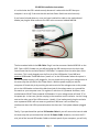
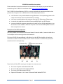
The first 3 connectors are for installing the 3 internal cables described below:
a. The 5V Power cable attaches at 5V CN3. It is then run to the back of your case or
somewhere in the case where you can mount this connector. Mounting the
connector will require a hole in the case that is 3/8” in diameter. This cable is 20”
long so keep that in mind when locating the IRS5 in the case.
b. The Motherboard Front Panel Power/LED header control cable attaches to the MB
FP Header. This has a number of small wires that are color coded and labeled. It
connects the Front Panel header Power Switch and LED cables to the IRS5 while still
allowing the cases power button and power LED to continue to function.
c. The last of the standard cables is the USB cable that attaches at USB and to the
motherboard internal USB 2.0 header.
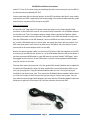
Finally, the optional IR Extender cable installation is similar to the 5V Power cable. It is
mounted somewhere inside the case. It requires a hole that is ¼” or 7mm in diameter. If
your case is a standard size with I/O plates for video and audio cards etc, you could use a
blank I/O plate and drill the holes needed for mounting the cables. This cable is 20” long.
Page 2