1
eDAM-8000 Analog
series
User’s manual
Web site: www.inlog.com.tw
Trademark:
The names used in this manual for indentification only
maybe registered trademarks of their respective companies
Rev 1.3
Printed 2002/10//23 Taiwan
-1-
-2-
Table of Contents
Chapter 1
1.1
1.2
1.3
1.4
1.5
1.6
Overview
................................................................... 7
Module Compatibility....................................................... 7
Communication and Programming ................................ 7
Software Configuration and Calibration......................... 7
Watchdog Timer.............................................................. 8
Power Requirements ...................................................... 8
Chapter 2
2.1
2.2
2.3
2.4
2.4.1
2.4.2
2.4.3
2.5
2.6
2.6.1
2.6.2
2.6.3
About the eDAM Analog Modules ................... 9
Outline of eDAM Analog modules .................................. 9
Module Dimension .......................................................... 10
eDAM Analog modules ................................................... 13
Specifications .................................................................. 14
eDAM-8012/8012D module ......................................... 14
eDAM-8014/14D module ............................................. 16
eDAM-8017 module ..................................................... 18
Block diagram of modules .............................................. 19
Wire connection .............................................................. 21
EDAM-8012/8012D wire connection ........................... 21
EDAM-8014/14D wire connection ............................... 21
EDAM-8017 wire connection ....................................... 22
Chapter 3
3.1
3.2
3.3
Introduction........................................................ 7
Pin definitions .................................................... 23
EDAM8012/8012D.......................................................... 23
EDAM8014/8014D.......................................................... 24
EDAM8017 ................................................................... 25
Chapter 4
Installation .......................................................... 27
-3-
4.1
4.2
4.3
4.4
4.5
4.6
4.7
4.8
4.9
Set up an eDAM network................................................ 28
Host computer................................................................. 28
Power supply................................................................... 29
Communication Wiring ................................................... 29
eDAM Utility Software ..................................................... 29
eDAM Isolated RS-232/RS485 Converter..................... 30
Initializing a Brand-New Module .................................... 30
Initialization Procedure ................................................... 31
Install a New eDAM to a Existing Network .................... 32
Chapter 5
5.1
5.2
5.3
5.4
5.4.1
5.4.2
5.4.3
5.4.4
5.4.5
5.5
5.6
5.7
5.8
5.9
5.10
5.11
5.12
5.13
-4-
Command Set .................................................... 33
Introduction ................................................................... 33
Format of eDAM Commands ......................................... 34
Response of Commands................................................ 36
Summary of Command Set ............................................ 37
eDAM Special commands............................................ 37
General Commands ..................................................... 38
Analog functional commands ...................................... 39
Digital functional Commands ....................................... 40
Linear mapping functional Commands ....................... 41
Set brand compatible...................................................... 42
Read current brand setting............................................. 43
Set Module configuration................................................ 44
Read Configuration......................................................... 49
Set module name............................................................ 50
Reset module .................................................................. 51
Read module name ........................................................ 52
Read firmware version.................................................... 53
Host OK
................................................................... 54
5.14
5.15
5.16
5.17
5.18
5.19
5.20
5.21
5.22
5.23
5.24
5.25
5.26
5.27
5.28
5.29
5.30
5.31
5.32
5.33
5.34
5.35
5.36
5.37
5.38
5.39
5.40
5.41
5.42
Read module’s status ..................................................... 55
Reset module status ....................................................... 56
Read host watchdog timeout value................................ 57
Set host watchdog timeout value ................................... 58
Read power-on/safe value ............................................. 61
Set power-on/safe value................................................. 63
Synchronized Sampling.................................................. 64
Read Synchronized data ................................................ 65
Read analog data............................................................ 66
Enable/disable calibration .............................................. 67
Span calibration .............................................................. 68
Offset calibration ............................................................. 69
Read data from channel N ............................................. 70
Read all analog data....................................................... 71
Enable/disable channel for multiplexing ........................ 72
Read channel status ....................................................... 73
Read LED configuration ................................................. 74
Set LED configuration..................................................... 75
Set LED data ................................................................... 76
Read Digital I/O and alarm status .................................. 77
Set Digital output channel............................................... 79
Clear latch alarm............................................................. 80
Clear event counter ........................................................ 81
Disable alarm .................................................................. 82
Enable alarm ................................................................... 83
Set high alarm ................................................................. 84
Set low alarm................................................................... 85
Read event counter ........................................................ 86
Read high alarm.............................................................. 87
-5-
5.43
5.44
5.45
5.46
5.47
5.48
5.49
Read low alarm ............................................................... 88
Read source HI/LO values for linear mapping .............. 89
Read target HI/LO values for linear mapping................ 90
Write source HI/LO values for linear mapping .............. 91
Write target HI/LO values for linear mapping ................ 91
Enable/disable linear mapping....................................... 93
Read linear mapping status ........................................... 95
Chapter 6
Data Format and Input range........................... 96
6.1
Data Format of Analog Input Modules ........................... 96
6.1.1 Engineering Units ......................................................... 96
6.1.2 Percent of FSR (Full Scale Range) ............................. 96
6.1.3 Two’s Complement Hexadecimal ................................ 96
Chapter 7
7.1
Calibration .......................................................... 98
Calibration for 8012/D,8014/D,8017 .............................. 98
Appendix A INIT*pin operation ............................................... 99
Appendix B Linear mapping .................................................101
Appendix C About high/low alarm .......................................102
Appendix D Power on/Safe value.........................................103
-6-
Chapter 1
1.1
Introduction
Overview
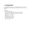
The eDAM-8000 analog modules is a set of intelligent sensor to
computer interface modules containing built-in microprocessor.
They provide data comparison, and digital communication
functions. Some modules provide analog I/O lines for controlling
and monitoring analog signals.
1.2
Module Compatibility
Communication and Programming
eDAM modules can connect to and communicate with all
computers and terminals. They use RS-485 transmission
standards, and communicate with ASCII format commands. All
communications to and from the module are performed in ASCII,
which means that eDAM modules can be programmed in virtually
any high-level language.
Up to 256 eDAM modules may be connected to an RS-485
multi-drop network by using the eDAM RS-485 repeater,
extending the maximum communication distance to 4,000 ft.
1.4
1.5
Power Requirements
Although the modules are designed for standard industrial
unregulated 24V DC power supply , they accept any power
unit that supplies power within the range of +10 to +30 V DC .
The power supply ripple must be limited to 5 V peak-to-peak,
and the immediate ripple voltage should be maintained
between +10 and +30 V DC .
Software Configuration and Calibration
EDAM modules contain no pots or switches to set. By merely
issuing a command from the host computer, you can change
an analog input module to accept several ranges of voltage
input.
-7-
Watchdog Timer
A watchdog timer supervisory function will automatically reset
the eDAM modules in the event of system failure.
Maintenance is thus simplified.
1.6
The eDAM-8000 series are fully compatible to Advantech
ADAM-4000 series, ADlink NµDAM-6000 series and ICP
I-7000 series by Command “~AA2X01V”
1.3
Remote configuration can be done by using the command
set’s configuration and calibration commands.
By storing configuration and calibration parameters in a
nonvolatile EEPROM, modules are able to retain these
parameters in case of power failure.
-8-
Chapter 2
2.1
About the eDAM Analog Modules
2.2
Outline of eDAM Analog modules
-9-
- 10 -
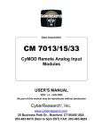
Module Dimension
- 11 -
- 12 -
2.3
2.4
eDAM Analog modules
The eDAM provides a series of analog input or digital in/output
modules to sense the analog and digital signal or to control the
remote devices.
• eDAM-8012 :
• eDAM-8012D:
• eDAM-8014:
• eDAM-8014D :
• eDAM-8017 :
Photo-isolated 1-channel analog input and 3
channel digital I/O module
Photo-isolated 1-channel analog input and 3
channel digital I/O module with seven segment
display
Photo-isolated 2-channel V/I input and 3
channel digital I/O module
Photo-isolated 2-channel V/I input and 3
channel digital I/O module with seven segment
display
Photo-isolated 8-channel analog input module
- 13 -
2.4.1
Specifications
eDAM-8012/8012D module
eDAM-8012/D provides one isolated analog input channel with
input type mV, V, mA, one digital input channel and two digital
output channels with common ground.
Specifications
Interface : RS-485, 2 wires
Speed: 1200, 2400, 4800, 9600, 19.2K, 38.4K ,115.2K
Analog input :
Channel: 1
Input type: mV, V, mA (with external 125 ohms shunt
resistor)
Sampling rate:
Normal mode: 10 samples /sec (default)
Fast mode: 100 samples/sec
Resolution: 20-bit
Bandwidth: 5.24Hz(normal mode)/52.4Hz(fast mode)
Input Impedance: 20M ohms
Isolation voltage: 3000VDC
Overvoltage protection: ±40V
LED display: 5 1/2 digits display (8012D only)
Digital output
Channel: 2
Output type: Open collector (30VDC max.)
Sink current: 300mA max.
Power dissipation: 300mW
- 14 -
Digital input
Channel: 1
Logical level 0: +1V max./Logical level 1: 3.5V to 30V
Event counter:
Maximum input frequency: 50Hz
Minimum input width: 1ms
Power input : +10V to +30VDC
Consumption: eDAM-8012 :1.4W, eDAM-8012D: 2.0W
- 15 -
2.4.2 eDAM-8014/14D module
eDAM-8014/D provides one isolated voltage analog input channel
and one current analog input channel with input type mV, V, mA,
one digital input channel and two digital output channels with
common ground
Specifications
Interface: RS-485, 2 wires
Speed: 1200, 2400, 4800, 9600, 19.2K, 38.4K ,115.2K
Analog Input
Channel: 1 voltage input and 1 current input
Input type: single-ended input
Unit conversion: mV, V, or mA
Voltage Range: ±10V, ±5V, ±1V, ±500mV, ±150mV
Current Measurement: ±20mA
Input impedance:
Voltage input: 20M ohms
Current input: 125 ohms
Accuracy: ±0.05%
Isolation Voltage: 3000 Vrms.
Over voltage protection: ±40V
Digital Output
Channel numbers: 2
Output characteristic: open collector transistor
Maximum current sink: 30mA
Max. power dissipation: 300mW
Digital Input
Channel numbers: 1
Logical level 0: +1V maximum
Logical level 1: +2.0V~30V
- 16 -
Pull up resister: 10K ohms
Event counter:
Maximum input frequency: 50Hz
Minimum input width: 1ms
Excitation voltage output: +15VDC @30mA
Power supply: +10V to +30V
Power consumption: 8014: 1.4 W/ 8014D: 2W
2.4.3 eDAM-8017 module
eDAM-8017 is an analog input module with 8 differential input
channels or six differential inputs and two single-ended inputs
Specifications
Interface : RS-485, 2 wires
Speed: 1200, 2400, 4800, 9600, 19.2K, 38.4K ,115.2K
Analog Input channels:
6 differential and 2 single–ended or 8 differential
Accuracy: ±0.1%(normal mode)/ ±0.5%(fast mode)
Sampling rate:
10 samples/sec (normal mode) (default)
75 samples/sec (fast mode)
Unit conversion: mV, V or mA
Voltage range: programmable 5 levels:
±10V, ±5V,±1V,±500mV,±150mV
Current measurement: 20mA (with 125 ohm shunt resistor)
Isolation Voltage: 3000 Vrms
Over voltage protection: ±40V
Storage Temperature Range: -25 to 80 °C
Operating Temperature Range: -10 to 70 °C
Power Requirement: +10V to +30VDC Unregulated
Power Consumption: 1.2W
Case: ABS with captive mounting hardware
- 17 -
- 18 -
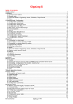
2.5
Block diagram of modules
eDAM-8012/D
+5V
Power
Power
Digital I/O
Micro
processor
(EEPROM)
Data+
Data-
GND
DO 1/HI
INIT
Micro
processor
Data+
+IN
ADC
Data-
-IN
VS
Isolated
Power
GND
eDAM-8014/D
+5V
Power
DI 0/EV
Digital I/O
INIT
Micro
processor
DO 0/LO
DO 1/HI
(EEPROM)
Data-
Iin+
Photo-Isolation
RS-485
interface
Mux
Data+
ADC
+5V
VS
GND
Power
supply
Isolated
Power
+15Vout
+15Vout
125 ohms
IinVin+
Vin+15Vout
- 19 -
Vin 1ADC
(EEPROM)
RS-485
interface
LED indicator
Vin 1+
Photo-Isolation
Photo-Isolation
Power
supply
Vin 0-
LED indicator
DO 0/LO
RS-485
interface
+5V
VS
Vin 0+
DI 0/EV
LED indicator
INIT
eDAM-8017
+5V
- 20 -
Vin 2-
Vin 7+
Vin 7+5V
Power
supply
Vin 2+
Isolated
Power
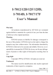
2.6
2.6.3
Wire connection
2.6.1
EDAM-8017 wire connection
EDAM-8012/8012D wire connection
125 ohms
Vin x+
Analog input
Digital output
Analog input
+IN
+IN
+
+
relay
DO0
mA
V
-
-IN
Vin x+
Vin x-
V
-
-IN
+
V
+
-
I
Vin x-
+
-
-
GND
125 ohms
Digital input(1)
Digital input(2)
DI0
DI0
GND
GND
GND
2.6.2
Differential analog input for channel 0 to channel 7
Digital input(3)
DI0
Analog input mode for channel 6 can channel 7 can be selected by
setting JP1 on the board
Differential input channel 6 and 7 Single-ended input channel 6 and 7
EDAM-8014/14D wire connection
JP1
Analog input
Vin 6+
Digital output
+IN
relay
DO0
+
+
V
-IN
V
-
JP1
Vin 6-
Vin 6+
+
V
-
-
GND
Digital input(2)
Digital input(3)
DI0
DI0
DI0
GND
GND
GND
3 wire transmitter
+15V
+IN
-IN
Vin 7/INIT
2 wire transmitter
+15V
3 wire
transmitter
+IN
Vin 6-
+
-
V
Vin 7+
Digital input(1)
V
2 wire
transmitter
-IN
- 21 -
- 22 -
Vin 7+
+
V
-
Vin 7/INIT
+
Chapter 3
3.1
pin
Pin definitions
3.2
EDAM8012/8012D
name
description
1
2
3
IN+
Analog Input Positive Terminal
INAnalog Input Negative Terminal
DO 1/HI Digital Output Channel 1 or High alarm status
output
4 DI 0 /EV Digital Input Channel 0 or event counter input
5 DO 0 /LO Digital Output Channel 0 or Low alarm output
6 INIT*
Initial state setting
7 DATA+ RS-485 series signal, positive
8 DATA- RS-485 series signal, negative
9 +Vs
Power supply, +10V~+30V
10 GND
Ground
- 23 -
EDAM8014/8014D
pin
name
description
1
2
3
6
7
8
9
10
11
12
13
18
19
20
+15V out
Iin+
IinINIT*
DATA+
DATA+Vs
GND
VinVin+
+15V out
DO 0 / LO
DI 0 / EV
DO 1/ HI
External +15V output
Current input positive terminal
Current input negative terminal
Initial state setting
RS-485 series signal, positive
RS-485 series signal, negative
Power supply, +10V~+30V
Ground
Analog input negative terminal
Analog input positive terminal
External +15V output
Digital output channel 0 or low alarm output
Digital input channel 0 or event counter input
Digital output channel 1 or high alarm status
output
- 24 -
3.3
EDAM8017
pin
name
description
1
2
Vin5+
Vin5-
3
4
Vin6+
Differential/single-ended input channel 6
Vin6-/AGND* Differential negative ground of channel 6 or
AGND for single-ended input channel 6 & 7
Vin7+
Differential/single-ended input channel 7
Vin7-/INIT** Differential negative ground of channel 7 or
Initial state setting
DATA+
signal, positive
DATAsignal, negative
+VS
+10V ~ +30Vdc
5
6
7
8
9
10 GND
11 Vin0+
12 Vin0-
Differential positive input channel 5
Differential negative input channel 5
Ground
Differential positive input channel 0
Differential negative input channel 0
13 Vin1+
Differential positive input channel 1
14 Vin1Differential negative input channel 1
15 Vin2+
Differential positive input channel 2
16 Vin2Differential negative input channel 2
17 Vin3+
Differential positive input channel 3
18 Vin3Differential negative input channel 3
19 Vin4+
Differential positive input channel 4
20 Vin4Differential negative input channel 4
* Negative input of channel 6 or common AGND of channel 6 and 7
depended on JP1 setting (see page 22)
** Negative input of channel 7 or INIT (Initial state setting) pin
- 25 -
- 26 -
Chapter 4
Installation
This chapter provides guidelines to what is needed to set up and
install an eDAM network. A quick hookup scheme is provided that
lets you configure modules before they are installed in a network.
To help you to connect eDAM modules with sensor inputs,
several wiring examples are provided. Finally, you will find at the
end of this chapter a programming example using the eDAM
command set.
Be sure to carefully plan the layout and configuration of your
network before you start. Guidelines regarding layout are given in
Appendix E: RS-485 Network.
NOTICE: Except for changing eDAM to other compatible
modules, which have on-board switches for their baud rate setting,
eDAM modules should not be opened. There is no need to open
the eDAM modules: all configuration is done remotely and there
are no user serviceable parts are inside. Opening the cover will
therefore void the warranty.
4.1
Set up an eDAM network
The following list gives an overview of what is needed to setup,
install and configure an eDAM environment.
A host computer that can output ASCII characters with an
RS-232C or RS-485 port.
Power supply for the eDAM modules (+10 to +30 VDC )
eDAM Series Utility software
4.2
Host computer
Any computer or terminal that can output in ASCII format over
either RS-232 or RS-485 can be connected as the host computer.
When only RS-232 is available, an eDAM-8520 module
(RS-232/RS-485 converter) is required to transform the host
signals to the correct RS-485 protocol. The converter also
provides opto-isolation and transformer-based isolation to protect
your equipment.
For the ease of use in industrial environments the eDAM modules
are designed to accept industry standard +24 VDC unregulated
power. Operation is guaranteed when using any power supply
between +10 and +30 VDC. Power ripples must be limited to 5 V
peak to peak while the voltage in all cases must be maintained
between +10 and +30 VDC . All power supply specifications are
referenced at module connector. When modules are powered
remotely, the effects of line voltage drops must be considered.
- 27 -
- 28 -
4.3
Power supply
All modules use on-board switching regulators to sustain good
efficiency over the 10-30V input range, therefore we can assume
that the actual current draw is inversely proportional to the line
voltage. The following example shows how to calculate the
required current that a power supply should be able to provide.
4.6
When the host computer or terminal has only a RS-232 port, an
eDAM-8520 Isolated RS-232/RS-485/422 converter connected to
the host’s RS-232 port is required.
This module equips a “Auto baud rate detector” inside, therefore it
can detect the baud rate and data format automatically and
control the direction of RS-485 precisely
4.7
4.4
Communication Wiring
We recommend that shielded-twisted-pair cables that comply with
the EIA RS-485 standard be used with the eDAM network to
reduce interference.
4.5
eDAM Utility Software
A menu-driven utility program called “DOSEDAM.EXE” for DOS
or “WINEDAM.EXE for Windows is provided for eDAM module
configuration, monitoring and calibration. It also includes a
terminal emulation program that lets you easily communicate
through the eDAM command set
- 29 -
eDAM Isolated RS-232/RS485 Converter
Initializing a Brand-New Module
All eDAM modules in a RS-485 network must have an unique
address ID. Therefore, to configure the brand-new 8012/D,
8014/D, 8017 before using is necessary
Factory default settings:
Address ID is 01
Baud rate is 9600 bps, check-sum disable
Analog input type: Type 08 (±10V)
60Hz filter rejection mode
Normal operation mode (for 8012/D, 8017)
Six differential and 2 single-ended input mode (for 8017)
INIT* State settings:
The eDAM I/O modules must be set at INIT* State when
you want to change the default settings, such as the ID
address, baud rate, check-sum status etc. All eDAM I/O
modules have an special pin labeled as INIT*. The module
will be in Default State if the INIT* pin is shorted to ground
when power ON. Under this state, the default configuration
is set as following :
Address ID is 00
Baud rate is 9600 bps
Check-sum disable
- 30 -
Therefore, the communication between host and the module will
can be easily set as the same configuration, the initialization of a
module will be possible no matter what configuration is set under
operating state.
4.8
Initialization Procedure
1. Power off the host computer and the installed eDAM-8520 to
COM port of host computer.
2. Connect a brand new eDAM module with the RS-485. Set the
module in Default State by shorting the INIT* pin to GND.
Refer to Figure 4.1 for detailed wiring.
3. Power on the power supply for eDAM modules.
4. Use the eDAM utility to configure the address ID, baud rate,
check-sum status and command sets of the module.
eDAM8520
HOST PC RS-232C
TX 3
RX 2
5
GND
Data+
3 TX Data2 RX
5 GND
eDAM I/O module
RS-485
VS
GND
Data+
Data-
INIT
VS
GND
4.9
1. Equipments for Install a New Module
2. A existing eDAM network
3. New eDAM modules.
4. Power supply (+10 to +30 VDC)
Installing Procedures
1. Configure the new eDAM module according to the initialization
procedure in section 4.7
2. The baud rate and check-sum status of the new module must
be identity with the existing RS-485 network. The address ID
must not be conflict with other eDAM modules on the network.
3. Power off the eDAM power supply of the existing RS-485
network.
4. Wire the power lines for the new eDAM with the existing
network. Be careful about the signal polarity as wiring.
5. Wire the RS-485 data lines for the new eDAM with the existing
network. Be careful about the signal polarity as wiring.
6. Wire to the input or output devices.
7. Power on the eDAM local power supply.
8. Use the eDAM utility to check entire network.
GND
Power supply
VS 10Vdc-30Vdc
Figure 4.1
- 31 -
Install a New eDAM to a Existing Network
- 32 -
Chapter 5
5.1
Command Set
5.2
Introduction
The eDAM command is composed by numbers of characteristics,
including the leading code, address ID, the variables, the optional
check-sum byte, and a carriage return to indicate the end of a
command.
The host computer can only command only one eDAM module
except those synchronized commands with wildcard address
command “#**”. The eDAM may or may not give response to the
command. The host should check the response to handshake
with the modules.
Format of eDAM Commands
Syntax: (Leading code)(Addr)(Command)[Data] <Cksum><CR>
Every command begins with a delimiter character. There are five
valid characters: a dollar sign $, a pound sign #, a percentage ,a
wave sign ’~’ ,sign % and an at sign @.
The delimiter character is followed by a two-character address
(hexadecimal) that specifies the target module. The actual two
character command follows the address. Depending on the
command, an optional data segment follows the command string.
An optional two character checksum may be appended to the
total string. Every commands is terminated by a carriage return
(cr).
Conventions
Leading Code The first characteristic of the eDAM command,
such as %,$,#,~, @, ...etc(1- character)
Addr
Module’s address ID, the value is in the range of
00 – FF (Hex) 2- character
Command
Command codes or value of variables
Data
Data needed by some output command
Checksum
Checksum in brackets indicate optional
parameter, only checksum is enable then this
field is required (2- character)
<CR>
carriage return( 0x0D)
Note:
1. all commands should be issued in ASCII uppercase
characters. There is no spacing between characters.
- 33 -
- 34 -
Calculate Checksum:
1. Calculate ASCII sum of all characters of command (or
response) string except the character return(cr)
2. Mask the sum of string with 0ffh
3. [Checksum]={(Leading code)+(addr)+(command)+[data]} MOD 0x100
Example:
Command string : $012(cr)
Sum of string=’$’+’0’+’1’+’2’=24h+30h+31h+32h=B7h
The checksum is B7h, and [CHK]=”B7”
Command string with checksum=$012B7(cr)
Response string : !01400600(cr)
Sum of string=’!’+’0’+’1’+’4’+’0’+’0’+’6’+’0’+’0’
=21h+30h+31h+34h+30h+30h+36h+30h+30h=1ACh
The checksum is ACh, and [CHK]=”AC”
Response string with checksum=!01400600AC(cr)
- 35 -
5.3
Response of Commands
The response message depends on eDAM command. The
response is also composed with several characteristics, including
leading code, variables, and carriage return for ending. There are
two kinds of leading code for response message, ”!“ or ”>“ means
valid command and ”?“ means invalid. By checking the response
message, user can monitor the command is valid or invalid.
But under the following conditions, there will have no response
message.
The specified address ID is not exist.
Syntax error.
Communication error
Some special commands does not have response.
- 36 -
5.4
5.4.2
Summary of Command Set
There are four categories of eDAM commands. The first is the
eDAM special commands. The second is the general
commands, The third is the analog commands., the forth is the
digital commands and the last is linear mapping commands.
All the commands used in the eDAM analog input module are list
in the following table.
5.4.1
eDAM Special commands
Modules page
General Commands
Command
Syntax
Modules page
Set configuration
%AANNTTCCFF All modules
44
Read configuration
$AA2
All modules
49
Set module Name
~AAO
All modules
50
Reset module
$AARS
All modules
51
Read module Name
$AAM
All modules
52
Read firmware Version
$AAF
All modules
53
Command
Syntax
Set brand compatible
~AA2X01V
All modules
42
Host OK
~**
Al modules
54
Read current brand setting
~AA2X02
All modules
43
Read module status
~AA0
All modules
55
Reset module status
!AA1
All modules
56
~AA2
All modules
57
~AA3EVV
All modules
58
~AA4
All modules
61
~AA5PPSS
All modules
63
Read host watchdog
timeout interval
Set watchdog timeout
interval
Read power on value/safe
value
Set power on value/safe
value
- 37 -
- 38 -
5.4.3
5.4.4
Analog functional commands
Command
Syntax
Modules
page
Digital functional Commands
Command
Syntax
Modules
page
Synchronized Sampling #**
8012/D,8014/D
64
8012/D,8014/D
77
Read Synchronized
Analog Data
Read Digital I/O and Alarm
@AADI
Status
$AA4
8012/D,8014/D
65
Set Digital Output
@AADODD
8012/D,8014/D
79
Read Analog Data
#AA
8012/D,8014/D
66
Clear Latch Alarm
@AACA
8012/D,8014/D
80
Span Calibration
$AA0
8012/D,8014/D,8017
67
Clear Event Counter
@AACE
8012/D,8014/D
81
Offset Calibration
$AA1
8012/D,8014/D,8017
69
Disable Alarm
@AADA
8012/D,8014/D
82
Read Data From Chan. N # AAN
8017
70
Enable Alarm
@AAEAM
8012/D,8014/D
83
Enable/disable calibration ~AAEV
8012/D,8014/D,8017
67
Set High Alarm
@AAHIDD
8012/D,8014/D
84
Read All Analog Data
$AAA
8017
71
Set Low Alarm
@AALODD
8012/D,8014/D
85
Enable/Disable Channel
for Multiplexing
$AA5VV 8017
72
Read Event Counter
@AARE
8012/D,8014/D
86
Read Channel Status
$AA6
8017
73
Read High Alarm
@AARH
8012/D,8014/D
87
Read LED configuration
$AA8
8012D,8014D
74
Read Low Alarm
@AARL
8012/D,8014/D
88
Set LED configuration
$AA8V
8012D,8014D
75
Set LED data
$AA9DD 8012D,8014D
76
- 39 -
- 40 -
5.4.5
5.5
Linear mapping functional Commands
Command
Read Source High/Low
Values for Linear Mapping
Read Target High/Low
Values for Linear Mapping
Write Source High/Low
Values for Linear Mapping
Write Target High/Low Values
for Linear Mapping
Enable/Disable Linear
Mapping
Syntax
$AA3
Modules page
8014/D
89
Set brand compatible
Modules:
All eDAM modules
Description:
Set compatible to other brand
Command:
~AA2X01V[CHK](cr)
~
Command leading code
AA
Module address ID (00 to FF)
2X
eDAM exclusive code
01
Set Compatible command.
$AA5
8014/D
90
$AA6(SL)(SH)
8014/D
91
$AA7(TL)(TH)
8014/D
92
V
Brand ID
$AAAV
8014/D
93
CHK
Check sum
(cr)
Carriage return
8014/D
93
Read Linear Mapping Status $AAA
Syntax:
0= eDAM , 1=ADAM
2=NuDAM, 3=I-7000
!AA[CHK](cr)
Valid Command
?AA[CHK](cr)
Invalid Command
!
Delimiter for valid command
Response:
?
AA
Delimiter for invalid command
Module address ID
CHK
Check sum
(cr)
Carriage return and then reboot module
Note: Module will be set to default states after this command issued
Example: Set eDAM-8017 module with ID=02 to command
.compatible to NuDAM-6017
Command: ~022X012(cr)
Response: !02((cr)
Example: Set eDAM-8012 module with ID=02 to command
.compatible to I-7012
Command: ~022X013(cr)
Response: !02(cr)
- 41 -
- 42 -
5.6
Read current brand setting
Modules:
All eDAM modules
Description:
Read current brand ID setting
Command:
~AA2X02[CHK](cr)
Syntax:
~
Command leading code
AA
Module address ID (00 to FF)
2X
eDAM exclusive code
02
Read Brand ID com..
5.7
Set Module configuration
Modules:
8012/D, 8014/D, 8017
Description: Set module configuration
Command:
Syntax:
CHK Check sum
(cr)
Carriage return
!AAV[CHK](cr)
Valid command
?AA[CHK](cr)
Invalid command
!
Delimiter for valid command
Response:
?
AA
Delimiter for invalid command
Module address ID
V
Brand ID
Response:
CHK Check sum
(cr)
Carriage return
Example: Read current brand ID of eDAM-8017 module with ID=02
Command: ~022X02(cr)
Response: !022((cr)
// Compatible to uDAM-6017
- 43 -
%AANNTTCCFF[CHK](cr)
%
Command leading code
AA
Module address ID (00 to FF)
NN
New eDAM address ID (00 to FF)
TT
Analog input range (See *)
CC
Set new baud rate of module (See **)
FF
Data format (See ***)
CHK Check sum
(cr)
Carriage return
!AA[CHK](cr) Valid command
?AA[CHK](cr) Invalid command
!
Delimiter for valid command
?
Delimiter for invalid command
AA
New Module address ID
CHK Check sum
(cr)
Carriage return
Note: The module will be reboot after sending this command
- 44 -
*Analog Input type and range (TT)
Input types and data format table
Type code
range
Modules
08
±10 V
8012/D,8017,8014/D
09
±5 V
8012/D,8017,8014/D
0A
±1 V
8012/D,8017,8014/D
0B
±500 mV 8012/D,8017,8014/D
0C
±150 mV 8012/D,8017,8014/D
0D
±20 mA
Code
03
8012/D,8017, 8014/D (Required
125Ω current conversion resistor.)
04
05
06
baud rate 1200 2400
4800
9600
07
08
09
0A
19200 38400 57600 115200
*** :Data format settings (FF)
Bit
7
6
5
4
3
Format
+F.S.
zero
-F.S
Engineer unit
+10.000 +00.000 -10.000
08
%of F.S.R
+100.00 +000.00 -100.00
2’s complement 7FFF
0000
8000
Engineer unit
+5.0000 +0.0000 -5.0000
-5~+5
09
%of F.S.R
+100.00 +000.00 -100.00
V
2’s complement 7FFF
0000
8000
Engineer unit
+1.0000 +0.0000 -1.0000
-1~+1
0A
%of F.S.R
+100.00 +000.00 -100.00
V
2’s complement 7FFF
0000
8000
Engineer unit
+500.00 +000.00 -500.00
-500~+500
0B
%of F.S.R
+100.00 +000.00 -100.00
mV
2’s complement 7FFF
0000
8000
Engineer unit
+150.00 +000.00 -150.00
-150~+150
0C
%of F.S.R
+100.00 +000.00 -100.00
mV
2’s complement 7FFF
0000
8000
Engineer unit
+20.000 +00.000 -20.000
-20~+20
0D
%of F.S.R
+100.00 +000.00 -100.00
mA
2’s complement 7FFF
0000
8000
Note:
It’s needed to short the INIT* pin to ground while changing baud
rate and/or enable/disable checksum (see following examples)
-10~+10
V
** Baud Rate settings (CC)
code
Range
2
1
0
Bit7: =0 for 60 Hz (default)
=1 for 50 Hz
Bit6: =1 Enable checksum
=0 Disable checksum (default setting)
Bit5: =0 for normal operation mode (Default setting)
=1 for fast operation mode (8012/D,8017)
Bit4~bit2: No used
Bit1~bit0 :=00 Engineer unit format (default setting)
=01 Percent format
=11 2’s complement Hex format
Example 1: Change ID address from 01 to 03 (Assume current baud
rate is 9600 and checksum disabled)
Command: %0103080600(cr)
Response: !03(cr)
response new module ID address 03 (change ID address only)
- 45 -
- 46 -
Example 2: Change baud rate from 9600 to 19200(Assume current
ID is 03, baud rate is 9600, and checksum disabled).
Because that the baud rate is changed from 9600 to 19200, the
following procedures should be done before sending this
command
1. Power off the module
2. Short INIT* pin to GROUND (see Appendix A)
3. Power on the module
4. send command string
Command: %0003080700(cr)
Response: !03(cr)
response module ID address 03
5. Power off module
6. Open INIT* pin
7. Power on module again ( Baud rate changed to 19200)
Example 3: Enable checksum(Assume current ID is 03, baud rate is
9600 and checksum disabled).
Because that the checksum is changed from disable to enable,
the following procedures should be done before sending this
command
1. Power off the module
2. Short INIT* pin to GROUND (see Appendix A)
3. Power on the module
4. send command string
Command: %0003080640(cr)
Response: !03(cr)
response module ID address 03
5. Power off module
6. Open INIT* pin
7. Power on module again (checksum enabled)
- 47 -
Example 4: Change baud rate from 9600 to 19200 and enable
checksum (Assume current ID is 03, baud rate is 9600
and checksum disabled).
Because that both the baud rate and checksum is changed , the
following procedures should be done before sending this
command
1. Power off the module
2. Short INIT* pin to GROUND (see Appendix A)
3. Power on the module
4. send command string
Command: %0003080740(cr)
Response: !03(cr)
response module ID address 03
5. Power off module
6. Open INIT* pin
7. Power on module again
( Baud rate changed to 19200 and checksum enabled)
It is recommended to use the setup utility to configure the module
(see section 4.7 and 4.8)
- 48 -
5.8
5.9
Read Configuration
Set module name
Modules:
For eDAM modules
Description: Read module configuration
Modules:
For all eDAM modules
Description: Set new module name.
Command:
Command:
Syntax:
Response:
$AA2[CHK](cr)
$
Command leading code
AA Module address ID (00 to FF)
2
Command for reading configuration
CHK Check sum
(cr) Carriage return
!AATTCCFF[CHK](cr) Valid command
?AA[CHK](cr)
Invalid command
!
Delimiter for valid command
?
AA
TT
CC
FF
CHK
(cr)
Syntax:
Delimiter for invalid command
Module address ID
Analog input type and range (see sec.5.7)
Baud rate (see sec.5.7)
Data format of module (see sec.5.7)
Check sum
Carriage return
Response:
(see Note)
~AAO(data)[CHK](cr)
$
Command leading code
AA
Module address ID (00 to FF)
O
Command for setting new name
(data) Module name, Max. 6 characters
CHK Check sum
(cr)
Carriage return
!AA [CHK](cr)
Valid command
?AA[CHK](cr)
Invalid command
!
Delimiter for valid command
?
AA
CHK
(cr)
Delimiter for invalid command
Module address ID
Check sum
Carriage return
Example 1: Set new module name at address ID=30
Command: ~30O4012<CR>
Set new name 4012 to the module at address ID=30
Response: !30<CR>
! Command is valid.,
Example 5: Read configuration of module with ID address=05
Command: $052(cr)
Response: !05080600(cr)
Read address ID=05 module configuration
08=Analog input range ±10 V
06=9600 baud rate
00=no checksum,
- 49 -
- 50 -
5.10
Reset module
Modules:
Description:
All eDAM modules
Reset all existing eDAM modules
Command:
$AARS[CHK](cr)
$
Command leading code
AA
Module address ID (00 to FF)
RS
Reset command
CHK Check sum
Syntax:
Response:
5.11
Read module name
Modules:
For eDAM DIO modules
Description: Read module‘s name
Command:
Syntax:
(cr) Carriage return
No response
Note: Reset command will reset module to default settings.
This command has no response from module
Response:
(see Note)
Example 1: Example: Reset module with ID address is 02
Command: $02RS(cr)
Response: No response
$AAM[CHK](cr)
$
Command leading code
AA Module address ID (00 to FF)
M
Command for reading module’s name
CHK Check sum
(cr) Carriage return
!AA(data)[CHK](cr) Valid command
?AA[CHK](cr)
Invalid command
!
?
Delimiter for valid command
Delimiter for invalid command
AA
data
CHK
(cr)
Module address ID
Module‘s name
Check sum
Carriage return
Example 1: Read module’s name of address ID=30
Command: $30M<CR>
Response: !308014<CR>
! Command is valid., Address ID=30, module’s name=8014
- 51 -
- 52 -
5.12
Read firmware version
5.13
Modules:
For eDAM DIO modules
Description: Read module‘s firmware version.
Command:
Syntax:
Response:
(see Note)
$AAF[CHK](cr)
$
Command leading code
AA Module address ID (00 to FF)
F
Command for reading firmware version.
CHK Check sum
(cr) Carriage return
!AA(data)[CHK](cr) Valid command
?AA[CHK](cr)
Invalid command
!
Delimiter for valid command
?
AA
data
CHK
(cr)
Delimiter for invalid command
Module address ID
Module‘s firmware version.
Check sum
Carriage return
Modules:
For all eDAM modules
Description: Host send this command to all modules for send
the information “Host OK”
Command: ~**[CHK](cr)
~
Command leading code
Syntax:
**
For all modules
CHK Check sum
(cr) Carriage return
Response: No response
Note:
When host watchdog timer is enable, host computer must send
this command to all module before timeout otherwise “Host
watchdog timer enabled” module‘s output value will go to safety
state output value.
Example 1: Read firmware version of module address ID=30
Command: $30F<CR>
Response: !30A1.04<CR>
! Command is valid., Address ID=30, Firmware
Version=A1.04
- 53 -
Host OK
- 54 -
5.14
5.15
Read module’s status
Modules:
For all eDAM modules
Description: Reset watchdog timeout status
Modules:
For all eDAM modules
Description: Read watchdog timeout status
Command:
Syntax:
Response:
Command:
~AA0[CHK](cr)
~
Command leading code
AA Module address ID (00 to FF)
0
Command for reading timeout status
CHK Check sum
(cr) Carriage return
! AASS[CHK](cr) Valid command
?AA[CHK](cr)
Invalid command
!
?
Reset module status
Syntax:
Delimiter for valid command
Delimiter for invalid command
Response:
AA
SS
Module address ID
SS=00 - watchdog timeout is cleared
SS=04 - watchdog timeout is set
SS=80 - watchdog activated
CHK Check sum
(cr) Carriage return
Note:
1. the watchdog timeout status will be stored in EEPROM of the
module and can only be cleared by issuing ~AA1 command
(see ~AA1 and ~AA3EVV commands)
2. When the module’s watchdog timeout value is reached, this
command will be responded with SS=04 otherwise SS=00
3. When the module’s watchdog timer is not timeout, this
command will be responded with SS=80
- 55 -
~AA1[CHK](cr)
~
Command leading code
AA Module address ID (00 to FF)
Command for resetting watchdog timeout
1
status
CHK Check sum
(cr) Carriage return
! AA [CHK](cr)
Valid command
?AA[CHK](cr)
Invalid command
!
Delimiter for valid command
?
Delimiter for invalid command
AA Module address ID
CHK Check sum
(cr) Carriage return
Note:
1. The module’s watch dog status will be cleared after this
command issued
2. (reference to ~AA3EVV command)
- 56 -
5.16
5.17
Read host watchdog timeout value
Modules:
For all eDAM modules
Description: Set host watchdog timeout value
Modules:
For all eDAM modules
Description: Read host watchdog timeout value
Command:
Syntax:
~AA2[CHK](cr)
~
Command leading code
AA
Module address ID (00 to FF)
2
Command for reading watchdog timeout
value
CHK Check sum
(cr) Carriage return
! AAEVV[CHK](cr) Valid command
?AA[CHK](cr)
Invalid command
!
?
Set host watchdog timeout value
Delimiter for valid command
Delimiter for invalid command
AA
E
Module address ID
Response:
Host watchdog enable/disable status
E=1 – Enabled
E=0 – Disabled
Timeout value in Hex format from 01
VV
to FF=25.5 seconds (one unit is 0.1 sec)
CHK Check sum
(cr) Carriage return
(also see sec 5.17)
Command:
Syntax:
Response:
~AA3EVV[CHK](cr)
~
Command leading code
AA Module address ID (00 to FF)
3
Command for setting watchdog timeout value
E
1= enable, 0= disable Host watchdog
VV Timeout value (01~FF, each for 0.1 second)
CHK Check sum
(cr) Carriage return
! AA [CHK](cr)
Valid command
?AA[CHK](cr)
Invalid command
!
Delimiter for valid command
?
AA
CHK
(cr)
Delimiter for invalid command
Module address ID
Check sum
Carriage return
Note:
If host watchdog timer is enabled, the host should send Host OK
(see section 5.13) command periodically within Timeout value to
refresh the timer, otherwise the module will be forced to safety state
(see section 5.19)
Example 1: Set module (ID=04) to have watchdog timeout value
10.0 seconds and enable host watchdog
- 57 -
Command: ~043164<cr>
Set watchdog timeout value 10.0 sec and enable host
watchdog
Response: !04<cr> Valid command
- 58 -
Example 2: Read watchdog timeout value form module (ID=04)
Command: ~042<cr>
Read watchdog timeout value
Response: !04164
Watchdog timeout value=10.0 seconds, and host watchdog
is enabled
Example 3: Reset watchdog timer
Example 6: Reset watchdog timeout status
Command: ~041<cr>
Reset watchdog timeout status
Response: !04<cr>
Watchdog timeout is cleared and LED stop flashing, and
host watchdog is disabled
Example 7: Read watchdog timeout status
Command: ~**<cr>
Read host watchdog timer
Stop sending any command string to modules for at least 10.0
seconds. The LED on the module will go to flash. The flash LED
indicates the host watchdog is timeout and timeout status is set
Command: ~040<cr>
Read module (ID=04) watchdog timeout status
Response: !0400<cr>
Timeout status is cleared
Example 4: Read watchdog timeout status
Command: ~040<cr>
Read module (ID=04) watchdog timeout status
Response: !0404<cr>
Timeout status is set
Example 5: Read watchdog timeout value form module (ID=04)
Command: ~042<cr>
Read watchdog timeout value
Response: !04164
Watchdog timeout value=10.0 seconds, and host watchdog
is enabled
- 59 -
- 60 -
5.18
Example 1: Read Power on /safe value
Read power-on/safe value
Modules:
For all eDAM modules
Description: Read Power on and safe value
Command:
~AA4[CHK](cr)
~
Command leading code
AA Module address ID (00 to FF)
4
Command for reading power on and safe
Syntax:
value
CHK Check sum
(cr) Carriage return
! AAPPSS[CHK](cr) Valid command
?AA[CHK](cr)
Invalid command
!
Delimiter for valid command
?
Delimiter for invalid command
Response:
AA Module address ID
(see Note)
PP Power on value (see *)
SS Safe value (see **)
CHK Check sum
(cr) Carriage return
* Power on value:
00=DO0 off and DO1 off
01=DO0 on and DO1 off
02=DO0 off and DO1 on
03=Do0 on and DO1 on
** Safe value:
00=DO0 off and DO1 off
01=DO0 on and DO1 off
02=DO0 off and DO1 on
03=Do0 on and DO1 on
- 61 -
Command: ~0344<cr>
Read power on value
Response: !041100<cr>
11=power on value
00=safe value
- 62 -
5.19
5.20
Set power-on/safe value
Modules:
For all eDAM modules
Description: Set current output value as power on or safe value
Command:
Syntax:
Response:
~AA5PPSS[CHK](cr)
~
Command leading code
AA Module address ID (00 to FF)
5
Command for setting power on or safe value
PP Power on value
00=DO0 off and DO1 off
01=DO0 on and DO1 off
02=DO0 off and DO1 on
03=DO0 on and DO1 on
SS Safe value
00=DO0 off and DO1 off
01=DO0 on and DO1 off
02=DO0 off and DO1 on
03=DO0 on and DO1 on
CHK Check sum
(cr) Carriage return
! AA [CHK](cr) Valid command
?AA[CHK](cr) Invalid command
!
?
AA
CHK
(cr)
Modules:
For 8012,8012D,8014,8014D
Synchronize
all modules to sample analog input
Description:
values and store the values in the module’s register at
the same time and use “Read Synchronized Data”
command to read the data and process it one by one.
Command: #**[CHK](cr)
#
Command leading code
Syntax:
**
Synchronized Sampling command
CHK Check sum
(cr)
Carriage return
Response: No response
Example 1: Synchronized Sampling
command: #**<CR>
Synchronized sampling command has no response
Delimiter for valid command
Delimiter for valid command
Module address ID
Check sum
Carriage return
Example 1: See sec.5.18
- 63 -
Synchronized Sampling
- 64 -
5.21
5.22
Read Synchronized data
Modules:
For 8012,8012D,8014,8014D
Description: Read synchronized data
Command:
Syntax:
Response:
(see Note)
Read analog data
Modules:
For 8012,8012D,8014,8014D,8017
Description: Read the ANALOG input value
Command: #AA[CHK](cr)
#
Command leading code
Syntax:
AA
Module address ID (00 to FF)
CHK
Check sum
(cr)
Carriage return
>(data)[CHK](cr)
Valid command
$AA4CHK](cr)
$
Command leading code
AA
Module address ID (00 to FF)
4
Command for reading synch. data
CHK Check sum
(cr)
Carriage return
!AAS(data)[CHK](cr) Valid command
? AA[CHK](cr)
Invalid command
Response:
(see Note)
!
?
Delimiter for valid command
Delimiter for invalid command
AA
Module address ID
S
(data)
CHK
(cr)
Data status, S=1 first read, S=0 been read
synchronized data
Check sum
Carriage return
Example 1: Read Synchronized data from eDAM8012 (ID=05)
?AA[CHK](cr)
Invalid command
>
Delimiter for valid command
?
Delimiter for invalid command
(data) Analog input data(see *)
CHK
Check sum
(cr)
Carriage return
* “DD” Analog input data:
If analog data of eDAM-8017 module be read by using this
command, data of all channels are responded as follows:
>(chan.0 data) (chan.1 data) …… (chan.7 data) [CHK](cr)
Example 1: Read analog input data from eDAM8012 at address=05
Command: $054(cr)
Response: !1097800(cr)
Read synchronized data from address ID=05 module
S=1 – first read
synchronized data=011+0.2556
Command: #05(cr)
Response: >+02.645(cr)
Read analog input data from address ID=05 module
Example 2: Read analog input data from eDAM8017 at address=05
Command: #05(cr)
Response:
+02.645-01.001+03.023+00.321+08.123-03.333+09.210-06.000(cr)
- 65 -
- 66 -
5.23
5.24
Enable/disable calibration
Modules:
For 8012,8012D,8014,8014D,8017
Description: Enable or disable Span calibration.
Command:
Syntax:
Response:
(see Note)
Modules:
For 8012/D,8014/D,8017
Description: To correct the gain errors of AD converter by
using the span calibration.
Command: $AA0[CHK](cr)
$
Command leading code
Syntax:
AA Module address ID (00 to FF)
0
Command for span calibration
CHK Check sum
(cr) Carriage return
!AA[CHK](cr)
Valid command
~AAEV[CHK](cr)
!
Command leading code
AA Module address ID (00 to FF)
E
Enable/disable calibration command
V
0=Disable span calibration
1=Enable span calibration
CHK Check sum
(cr) Carriage return
!AA[CHK](cr)
Valid command
?AA[CHK](cr)
Invalid command
!
Delimiter for valid command
?
AA
CHK
(cr)
Response:
(see Note)
Delimiter for invalid command
Module address ID (00 to FF)
Check sum
Carriage return
Note: send enable calibration command before performing the
calibration,
Example 1: Perform span calibration of module with address=06
Command: $06E1<CR>
Response: !06<CR>
Command: $060<CR>
Response: !06<CR>
Span calibration
?AA[CHK](cr)
Invalid command
!
Delimiter for valid command
?
AA
CHK
(cr)
Delimiter for invalid command
Module address ID (00 to FF)
Check sum
Carriage return
Note: To perform the calibration, a proper input signal should be
connected to the analog input module. Different input range have
different input voltage, detail refer Chapter 7 “Calibration”.
Example 2: Perform span calibration of module with address=06
Command: $060<CR>
Response: !06<CR>
// Enable calibration
// perform span calibration
- 67 -
- 68 -
5.25
5.26
Offset calibration
Modules:
For 8012,8012D,8014,8014D,8017
Description: To correct the offset errors of AD converter by
using the offset calibration
Command: $AA1[CHK](cr)
$
Command leading code
Syntax:
AA Module address ID (00 to FF)
1
Command for offset calibration
CHK Check sum
(cr) Carriage return
!AA[CHK](cr)
Valid command
Response:
(see Note)
Read data from channel N
Modules:
For eDAM 8017 only
Description: Read the analog input value of a specified AD
channel from an analog input module
Command: #AAN[CHK](cr)
$
Command leading code
Syntax:
AA
Module address ID (00 to FF)
N
Command for reading analog input
value
CHK
Check sum
(cr)
Carriage return
>(data)[CHK](cr)
Valid command
?AA[CHK](cr)
Invalid command
!
Delimiter for valid command
?
AA
CHK
(cr)
Response:
(see Note)
Delimiter for invalid command
Module address ID (00 to FF)
Check sum
Carriage return
Note:
To perform the calibration, a proper input signal should be connected
to the analog input module. Different input range have different input
voltage, detail refer Chapter 7 “Calibration”.
Example 1: Perform offset calibration of module with address=06
?
(data)
CHK
(cr)
Delimiter for invalid command
Analog input data
Check sum
Carriage return
Example 1: Read the analog input channel 1 of AD module at
address 06 in the network. (Data format is engineering
unit)
User command: #061<CR>
Response: >+1.6888<CR>
Command: $061<CR>
Response: !06<CR>
- 69 -
?AA[CHK](cr)
Invalid command
>
Delimiter for valid command
- 70 -
5.27
5.28
Read all analog data
Modules:
For eDAM 8017 only
Description: Read all the analog input channel value from
8017
Command: $AAA[CHK](cr)
$
Command leading code
Syntax:
AA
Module address ID (00 to FF)
A
Command for reading all channels
CHK
Check sum
(cr)
Carriage return
>(data0)..(data7)[CHK](cr) Valid command
Modules:
For eDAM 8017 only
Description: Enable/Disable multiplexing simultaneously for
individual channel.
Command: $AA5VV[CHK](cr)
$
Command leading code
Syntax:
AA Module address ID (00 to FF)
5
Command for reading digital I/O status
VV bit 3~0 of 1st character control channel 7-4
bit 3~0 of 2nd character control channel 3-0
bit value 0: Disable channel
bit value 1: Enable channel
CHK Check sum
(cr) Carriage return
!AA[CHK](cr) Valid command
?AA[CHK](cr)
Invalid command
>
Delimiter for valid command
Response:
(see Note)
?
(data)
CHK
(cr)
Enable/disable channel for multiplexing
Delimiter for invalid command
Data string of all channels in 2’s
complement Hex format (see *)
Check sum
Carriage return
Response:
(see Note)
* “data” Analog input data:
data of all channels are responded as follows:
>(chan.0 data) (chan.1 data) …… (chan.7 data) [CHK](cr)
Example 1: Read all analog input data from eDAM8017 , assume
address=03
Command: $03A(cr)
Response: 000132112321A221C001B12321103443(cr)
?AA[CHK](cr) Invalid command
!
Delimiter for valid command
?
AA
CHK
(cr)
Delimiter for invalid command
Module address ID (00 to FF)
Check sum
Carriage return
Example 1: Enable channel 3 and channel 6, the other channels are
all disable of eDAM-8017.
Command: $06548<CR>
‘48’ is 01001000 that means enable channel 3 and
channel 6, the other channels are all disable.
Response: !06<CR>
- 71 -
- 72 -
5.29
5.30
Read channel status
Modules:
For eDAM 8017 only
Description: Read the enable/disable status the channels of
eDAM-8017
Command: $AA6[CHK](cr)
$
Command leading code
Syntax:
AA Module address ID (00 to FF)
6
Command for reading channel status
CHK Check sum
(cr) Carriage return
!AAVV[CHK](cr)
Valid command
Read LED configuration
Modules:
For eDAM-8012D,8014D
Description: Read LED control status
Command:
Syntax:
?AA[CHK](cr)
Invalid command
!
Delimiter for valid command
?AA[CHK](cr)
Invalid command
!
Delimiter for valid command
Response:
(see Note)
?
AA
VV
CHK
(cr)
Response:
(see Note)
Delimiter for invalid command
Module address ID (00 to FF)
Channel status (See sec 5.28)
Check sum
Carriage return
Example 1: Read channel status of eDAM-8017 with address=06.
Command: $066<CR>
Response: !0648<CR>
4 is equals binary 0100 that means enable channel 6 and
disable channel 7, 5, 4.
8 is equals binary 1000 that means enable channel 3 and
disable channel 2, 1, 0.
- 73 -
$AA8[CHK](cr)
$
Command leading code
AA Module address ID (00 to FF)
8
Command for reading LED status
CHK Check sum
(cr) Carriage return
!AAV[CHK](cr)
Valid command
?
AA
V
Delimiter for invalid command
Module address ID (00 to FF)
LED control status
1=LED controlled by module
2=LED controlled by host
CHK Check sum
(cr) Carriage return
Example 1: Read LED control status of eDAM-8012D at address=03
Command: $038(cr)
Response: !032(cr)
The module LED is controlled by host
- 74 -
5.31
5.32
Set LED configuration
Modules:
For eDAM-8012D,8014D
Description: Set module LED control mode
Command:
Syntax:
Response:
(see Note)
Modules:
For eDAM-8012D,8014D
Description: Set LED display data when LED controlled by
host
Command: $AA9(data)[CHK](cr)
$
Command leading code
Syntax:
AA
Module address ID (00 to FF)
9
Command for setting LED data
(data) LED display data from –19999. to
+19999.
CHK
Check sum
(cr)
Carriage return
!AA[CHK](cr)
Valid command
$AA8V[CHK](cr)
$
Command leading code
AA Module address ID (00 to FF)
8
Command for setting LED control
V
LED control status
1=LED controlled by module
2=LED controlled by host
CHK Check sum
(cr) Carriage return
!AA[CHK](cr)
Valid command
?AA[CHK](cr)
Invalid command
!
Delimiter for valid command
?AA[CHK](cr)
Invalid command
!
Delimiter for valid command
?
AA
CHK
(cr)
Set LED data
Response:
Delimiter for invalid command
Module address ID (00 to FF)
Check sum
Carriage return
Example 1: Set LED control to host of eDAM-8012D at address=03
Command: $0382(cr)
Response: !03(cr)
?
AA
CHK
(cr)
Delimiter for invalid command
Module address ID (00 to FF)
Check sum
Carriage return
Example 1: Set LED display data “+32.120” of eDAM-8012D at
address=03
Command:$039+32.120(cr)
Repsonse:!03(cr)
- 75 -
- 76 -
5.33
Example 1: Read digital I/O and alarm at address 06H.
Read Digital I/O and alarm status
Modules:
For eDAM-8012,8012D,8014,8014D
Description: Read the digital input channel value and
readback the digital output channel value.
Command: @AADI[CHK](cr)
@ Command leading code
Syntax:
AA Module address ID (00 to FF)
DI
Command for reading DI/O & alarm status
CHK Check sum
(cr) Carriage return
!AASDODI[CHK](cr) Valid command
Command: @06DI<CR>
Response: !0620301<CR>
alarm state is LATCH, digital output channel port 0 and 1
are ON and digital input channel is HIGH.
?AA[CHK](cr)
Invalid command
!
Delimiter for valid command
?
AA
S
Response:
(see Note)
Delimiter for invalid command
Module address ID (00 to FF)
Alarm status(1-character)
0: alarm is disable
1: MOMENTARY mode enable.
2: LATCH mode enable.
DO Digital output status(2-character)
00=DO0 off,DO1 off
01=DO0 on,DO1 off
10=DO0 off,DO1 on
11=DO0 on,DO1 on
DI
Digital input status(2-character)
00: channel is LOW.
01: channel is HIGH.
CHK Check sum
(cr) Carriage return
- 77 -
- 78 -
5.34
5.35
Set Digital output channel
Clear latch alarm
Modules:
For eDAM-8012,8012D,8014,8014D
Description: Set digital output channels
Modules:
For eDAM-8012,8012D,8014,8014D
Description: Clear latch alarm
Command: @AADODD[CHK](cr)
@
Command leading code
AA
Module address ID (00 to FF)
Syntax:
DO
Output command type
DD
Digital output data(2-characters)
00: bit 1 is off, bit 0 is off
01: bit 1 is off, bit 0 is on.
02: bit 1 is on , bit 0 is off
03: bit 1 is on , bit 0 is on.
CHK Check sum
(cr)
Carriage return
!AA[CHK](cr) Valid command
?AA[CHK](cr) Invalid command
!
Delimiter for valid command
?
Delimiter for invalid command
Response: AA
Module address ID (00 to FF)
CHK Check sum
(cr)
Carriage return
Command: @AACA[CHK](cr)
@
Command leading code
AA
Module address ID (00 to FF)
Syntax:
CA
Clear alarm command
(cr)
Carriage return
!AA[CHK](cr) Valid command
?AA[CHK](cr) Invalid command
!
Delimiter for valid command
?
Delimiter for invalid command
Response: AA
Module address ID (00 to FF)
CHK Check sum
Example 1: Clear the both High/Low latch alarm state at address
06H.
Command: @06CA<CR>
Response: !06<CR>
Example 1: Set the digital output channel state at address 06H,
digital output channel port 0 is OFF, port 1 is ON.
Command: @06DO02<CR>
Response: !06<CR>
- 79 -
- 80 -
5.36
5.37
Clear event counter
Disable alarm
Modules:
For eDAM-8012,8012D,8014,8014D
Description: Clear event counter
Modules:
For eDAM-8012,8012D,8014,8014D
Description: Disable alarm
Command: @AACE[CHK](cr)
@
Command leading code
AA
Module address ID (00 to FF)
Syntax:
CE
Clear event counter command
CHK Check sum
(cr)
Carriage return
!AA[CHK](cr) Valid command
?AA[CHK](cr) Invalid command
Response: !
Delimiter for valid command
?
Delimiter for invalid command
CHK Check sum
(cr)
Carriage return
Command: @AADA[CHK](cr)
@
Command leading code
AA
Module address ID (00 to FF)
Syntax:
DA
Disable alarm command
CHK Check sum
(cr)
Carriage return
!AA[CHK](cr) Valid command
?AA[CHK](cr) Invalid command
Response: !
Delimiter for valid command
?
Delimiter for invalid command
CHK Check sum
(cr)
Carriage return
Example 1: Clear event counter at address 06H.
Example 1: Disable all alarm functions at address 06H.
Command: @06CE<CR>
Response: !06<CR>
Command: @06DA<CR>
Response: !06<CR>
- 81 -
- 82 -
5.38
5.39
Enable alarm
Set high alarm
Modules:
For eDAM-8012,8012D,8014,8014D
Description: Enable alarm
Modules:
For eDAM-8012,8012D,8014,8014D
Description: Set high alarm value
Command: @AAEAM[CHK](cr)
@
Command leading code
AA
Module address ID (00 to FF)
Syntax:
EA
Enable alarm command
M
M= enable alarm to MOMENTARY mode.
L=enable alarm to LATCH mode.
CHK Check sum
(cr)
Carriage return
!AA[CHK](cr) Valid command
?AA[CHK](cr) Invalid command
Response: !
Delimiter for valid command
?
Delimiter for invalid command
CHK Check sum
(cr)
Carriage return
Command: @AAH(data)[CHK](cr)
@
Command leading code
AA
Module address ID (00 to FF)
Syntax:
HI
Set high alarm command
(data) High alarm value in engineer unit
CHK Check sum
(cr)
Carriage return
!AA[CHK](cr) Valid command
?AA[CHK](cr) Invalid command
!
Delimiter for valid command
?
Delimiter for invalid command
Response: CHK Check sum
(cr)
Carriage return
Example 1: Enable alarm to MOMENTARY mode at address 06H.
Command: @06EAM<CR>
Response: !06<CR>
Example 1: Set high alarm limit value to +10.000 for analog input at
address 03H.
Command: @03HI+10.000<CR>
Response: !03<CR>
(Refer to Appendix C)
- 83 -
- 84 -
5.40
5.41
Set low alarm
Read event counter
Modules:
For eDAM-8012,8012D,8014,8014D
Description: Set low alarm value
Modules:
For eDAM-8012,8012D,8014,8014D
Description: Read the event counter value
Command: @AALO(data)[CHK](cr)
@
Command leading code
AA
Module address ID (00 to FF)
Syntax:
HI
Set low alarm command
(data) low alarm value in engineer unit
CHK Check sum
(cr)
Carriage return
!AA[CHK](cr) Valid command
?AA[CHK](cr) Invalid command
!
Delimiter for valid command
?
Delimiter for invalid command
Response: CHK Check sum
(cr)
Carriage return
Command: @AARE[CHK](cr)
@
Command leading code
AA
Module address ID (00 to FF)
Syntax:
RE
Read event counter command
CHK Check sum
(cr)
Carriage return
!AA(data)[CHK](cr) Valid command
?AA[CHK](cr)
Invalid command
!
Delimiter for valid command
?
Delimiter for invalid command
Response: AA
Module address ID (00 to FF)
(data) Event counter value(from 00000 to 65535)
CHK Check sum
(cr)
Carriage return
Example 1: Set low alarm limit value to +00.400 for analog input at
address 03H.
Command: @03LO+00.400<CR>
Response: !03<CR>
Example 1: Read event counter at address 03H
Command: @03RE<CR>
Response: !0312340<CR>
its value is 12340 (Decimal) at address 03H.
(Refer to Appendix C)
- 85 -
- 86 -
5.42
Read high alarm
5.43
Modules:
For eDAM-8012,8012D,8014,8014D
Description: Read the high alarm limit at specified analog input
module.
Command: @AARH[CHK](cr)
@
Command leading code
AA
Module address ID (00 to FF)
Syntax:
RH
Read high alarm value command
CHK Check sum
(cr)
Carriage return
!AA(data) [CHK](cr) Valid command
?AA[CHK](cr)
Invalid command
!
Delimiter for valid command
?
Delimiter for invalid command
Response: (data) High alarm limit value in engineering units.
CHK Check sum
Example 1: Read the high alarm limit value at address 03H,
Read low alarm
Modules:
For eDAM-8012,8012D,8014,8014D
Description: Read the low alarm limit at specified analog input
module.
Command: @AARL[CHK](cr)
@
Command leading code
AA
Module address ID (00 to FF)
Syntax:
RL
Read low alarm value command
CHK Check sum
(cr)
Carriage return
!AA(data)[CHK](cr) Valid command
?AA[CHK](cr)
Invalid command
!
Delimiter for valid command
?
Delimiter for invalid command
Response: (data) low alarm limit value in engineering units.
CHK Check sum
Example 1: Read the low alarm limit value at address 03H,
Command: @03RH<CR>
Response: !03+01.420<CR>
High alarm value is 1.420 Volts,
Command: @03RH<CR>
Response: !03+0.3420<CR>
Low alarm value is +0.3420 Volts,
(Refer to Appendix C)
(Refer to Appendix C)
- 87 -
- 88 -
5.44
Read source HI/LO values for linear mapping
Modules:
For eDAM-8014,8014D
Description: Read source high/low limit values from input for
linear mapping.
Command: $AA3[CHK](cr)
$
Command leading code
AA
Module address ID (00 to FF)
Syntax:
3
Read source HI/LO values command
CHK Check sum
(cr)
Carriage return
!AA(SL)(SH)[CHK](cr) Valid command
?AA[CHK](cr)
Invalid command
>
Delimiter for valid command
?
Delimiter for invalid command
Response: (SL) Low limit value in engineering unit for linear
mapping.
(SH) High limit value in engineering unit for linear
mapping.
CHK Check sum
Example 1: Read the high/low values for linear mapping. The
address of this module is 02H.
5.45
Read target HI/LO values for linear
mapping
Modules:
For eDAM-8014,8014D
Description: Read target high/low limit values from input for linear
mapping.
Command: $AA5[CHK](cr)
$
Command leading code
AA
Module address ID (00 to FF)
Syntax:
5
Read target HI/LO values command
CHK Check sum
(cr)
Carriage return
!AA(TL)(TH)[CHK](cr) Valid command
?AA[CHK](cr)
Invalid command
>
Delimiter for valid command
?
Delimiter for invalid command
Response: (TL)
Low limit value in engineering unit for linear
mapping.
(TH) High limit value in engineering unit for linear
mapping.
CHK Check sum
Example 1: Read the target high/low values for linear mapping. The
address of this module is 02H.
Command: $023<CR>
Response: !02+04.000+20.000<CR>
The high limit value is +20mA and low limit value is +4mA
The linear mapping function should already have been
executed.
(refer to Appendix B)
Command: $025<CR>
Response: !02+04.000+20.000<CR>
The high limit value is +20mA and low limit value is +4mA
The linear mapping function should already have been
executed.
(refer to Appendix B)
- 89 -
- 90 -
5.46
Write source HI/LO values for linear
mapping
5.47
Modules:
For eDAM-8014,8014D
Description: Write source HI/LO values for linear mapping. HI/LO
values will be permanently stored into EEPROM on
the module after #AA7(TL)(TH)(cr) command
applied (see sec 5.47)
Command: $AA6(SL)(SH)[CHK](cr)
$
Command leading code
AA
Module address ID (00 to FF)
Syntax:
6
Write source HI/LO values command
(SL) Low limit input value in engineering unit for
(SH)
linear mapping. It must be lower than the
high limit input value.
High limit input value in engineering unit for
linear mapping. It must be higher than the
low limit input value.
CHK Check sum
(cr)
Carriage return
!AA[CHK](cr) Valid command
?AA[CHK](cr) Invalid command
!
Delimiter for valid command
Response: ?
Delimiter for invalid command
AA
Module address ID (00 to FF)
CHK Check sum
(cr)
Carriage return
Example: (see sec 5.47)
Write target HI/LO values for linear
mapping
Modules:
For eDAM-8014,8014D
Write
target HI/LO values for linear mapping. This
Description:
command need be followed with $AA6(SL)(SH)
Command: $AA7(TL)(TH)[CHK](cr)
$
Command leading code
AA
Module address ID (00 to FF)
Syntax:
7
Write target HI/LO values command
Low limit input value in engineering unit for
(TL)
(TH)
linear mapping. It must be lower than the
high limit input value.
High limit input value in engineering unit for
linear mapping. It must be higher than the
low limit input value.
CHK Check sum
(cr)
Carriage return
!AA[CHK](cr) Valid command
?AA[CHK](cr) Invalid command
!
Delimiter for valid command
Response: ?
Delimiter for invalid command
AA
Module address ID (00 to FF)
CHK Check sum
(cr)
Carriage return
Example 1: set the source input high/low values from +120.00
to –160.00mV for linear mapping. The address of this
module is 03H.
Command: $036-160.00+120.00<CR>
Response: !03<CR>
- 91 -
- 92 -
Example 2: set the target input high/low values from +120.00
to –160.00 for linear mapping. The address of this
module is 03H.
5.48
Command: $037-160.00+120.00<CR>
Response: !03<CR>
Note:
The source HI/LO values and target HI/LO values will be stored
into EEPROM on the module after “Write target HI/LO values for
linear mapping” command applied
Enable/disable linear mapping
Modules:
For eDAM-8014,8014D
Description: Enable or disable the linear mapping function for the
module.
Command: $AAAS[CHK](cr)
$
Command leading code
AA
Module address ID (00 to FF)
Syntax:
A
Enable/disable the linear mapping command
S
1: means enable.
0: means disable.
CHK Check sum
(cr)
Carriage return
!AA[CHK](cr) Valid command
?AA[CHK](cr) Invalid command
!
Delimiter for valid command
?
Delimiter for invalid command
Response: AA
Module address ID (00 to FF)
CHK Check sum
(cr)
Carriage return
Example 1: set the linear mapping function enable, the address of
this module is 03H.
Command: $03A1<CR>
Response: !03<CR>
(refer to Appendix B)
- 93 -
- 94 -
5.49
Chapter 6
Read linear mapping status
Modules:
For eDAM-8014,8014D
Description: Read enable or disable the linear mapping status for
the module.
Command: $AAA[CHK](cr)
$
Command leading code
AA
Module address ID (00 to FF)
Syntax:
A
Read linear mapping status
CHK Check sum
(cr)
Carriage return
!AAS[CHK](cr) Valid command
?AA[CHK](cr) Invalid command
!
Delimiter for valid command
?
Delimiter for invalid command
Response: AA
Module address ID (00 to FF)
S
1: means enable.
0: means disable.
CHK Check sum
(cr)
Carriage return
Example 1: Read linear mapping function enable, the address of this
module is 03H.
Command: $03A<CR>
Response: !030<CR>
the linear mapping function is disable,
6.1
Data Format and Input range
Data Format of Analog Input Modules
There are three types of data format used in analog input
modules.
1. Engineering units.
2. Percent of FSR (Full Scale Range).
3. Two’s complements hexadecimal.
6.1.1
Engineering Units
Example 1: Input Range is ±5 V
Input is -1.37 Volts
engineering units: -1.3700<CR>
Example 2: Input Range is ±10 V
Input is +3.653 Volts
engineering units: +03.653<CR>
6.1.2
Percent of FSR (Full Scale Range)
Example 1: Input Range is ±5 V
Input is +1 Volts
% of FSR: +020.00<CR> (+(20/100) x 5 V) = +1 V
Example 2: Input Range is ±10 V
Input is +4 Volts
% of FSR: +040.00<CR> (+(40/100) x 10 V) = +4 V
6.1.3
Two’s Complement Hexadecimal
Example 1: Input Range is ±5 V
Input is +1 Volts
Two’s complement hexadecimal: 1999<CR>
((1/5) x 32768) = 6553.6 = 1999H
(refer to Appendix B)
- 95 -
- 96 -
Chapter 7
Example 2: Input Range is ±5 V
Input is -2 Volts
Two’s complement hexadecimal: CD27<CR>
((-2/5) x 32768) = -13107.2 = CD27H
7.1
Calibration
Calibration for 8012/D,8014/D,8017
The offset calibration is used to calibrate output offset when the
input voltage is 0V
The span calibration is used to calibrate the full scale output when
the input is full scale voltage
Calibration procedures
1. Apply zero voltage to channel 0 of analog module
(refer to sec 2.6)
2. Issues configuration command with type=08
(refer to sec 5.7)
3. Issues enable calibration command
4. Issues zero offset calibration command five times
5. Apply span voltage to channel 0 of analog module
6. Issues span calibration command five times
7. Repeat procedure 1 to procedure 6 two times
Example 3: Input Range is ±10 V
Input is +4 Volt
Two’s complement hexadecimal: 3333<CR>
((4/10) x 32768) = 13107.2 = 3333H
Type code
08
09
0A
0B
0C
0D
Zero input
0V
0V
0V
0mV
0mV
0mA
Span input
+10V +5V +1V +500mV +150mV +20mA
Table 7-1: 8012/D,8014/D,8017 Calibration voltages
Note:
While using calibration type 0D to calibrate 8012/D, 8017 module, an
external shunt resistor 125 ohms should be connected to channel 0
of module
- 97 -
- 98 -
Appendix A INIT*pin operation
Configuring the module baud rate and checksum
The “INIT*mode” has two purposes, one for reading module
current configuration, and another for configuring the module
baud rate and checksum
■
Reading module current configuration
Each eDAM module has a built-in EEPROM which is used to
store the configuration information such as address ID, type, baud
rate etc..
If the user unfortunately forget the configuration of the module.
User may use a special mode called “INIT* mode” to resolve the
problem
When the module is set to “INIT*” mode”, the default settings are
ID=00, baud rate=9600, and checksum=disable
The module should be set to “INIT* mode”, While changing baud
rate and/or checksum state by sending “Set module configuration”
command ( see section 5.7)
The following steps show you how to enable INIT* mode and
change baud rate and/or checksum state
1. Power off the module
2. Connect the “INIT*” pin to GND pin
3. Power on the module
4. Send command %AANNTTCCFF in 9600 baud rate to
set baud rate and/or checksum state (ID should be set
to 00 in “INIT* mode”)
5. Power off the module again
6. Open “INIT*” pin to force the module to normal mode
The following steps show you how to enable INIT* mode and read
the current configuration
,
1. Power off the module
2. Connect the “INIT*” pin to GND pin
3. Power on the module
4. Send command $002<cr> in 9600 baud rate to read the
current configuration stored in the EEPROM
5. Power off the module again
6. Open “INIT*” pin to force the module to normal mode
■
- 99 -
- 100 -
Appendix B Linear mapping
Appendix C
The linear mapping function is a mechanism that convert the
analog input value into the physical quantity, such as load cell,
pressure, water level etc.
The formula of linear mapping is
Output value =
(Vin − VSL )
× (VTH − VTL ) + VTL
(VSH − VSL )
Where
Vin =analog input value
VSL =Source low value for linear mapping
VSH =Source high value for linear mapping
VTL =Target low value for linear mapping
VTH =Target high value for linear mapping
Assume a load cell has voltage output range from 5mV to 80mV
which relates to 0Kg to 50Kg in physical quantity
The modules equipped with high/low alarm function will output a
signal to outside world to indicate the input data has been over or
under the alarm margin
The DO0 and DO1 are both used to output alarm signal when
alarm function is enabled. The DO0 is low alarm indicator, and the
DO1 is high alarm indicator (DO0 and DO1 can’t be controlled by
digital output commands when alarm function enabled)
When analog input value over high alarm value, the DO1 is ON
else is OFF
When analog input value under low alarm value, the DO0 is ON
else is OFF
The analog input value is compared to high alarm value and low
alarm value. There are two types:
1. Momentary alarm: Alarm signal automatically cleared while
the analog input data is not over/under the alarm values
2. Latch alarm: Alarm signal is always activated until the user
send alarm clear command
1. Set 8014D to have ±150 mV range by using command
%AANNTTCCFF(cr) (see sec 5.7)
2. Set source low value(VSL=+005.00) and source high
value(VSH=+080.00) by using command $AA6(SL)(SH)(cr)
(see sec 5.46) ($AA6+005.00+080.00(cr))
3. Set target low value(VTL=+000.00) and target high
value(VTH=+050.00) by using command $AA7(TL)(TH)(cr)
see sec 5.47) ($AA7+000.00+050.00(cr))
4. Enable linear mapping function by using $AAA1(cr)
(see sec 5.48)
5. The output data to host will be ranged from 00Kg to 50Kg
- 101 -
About high/low alarm
- 102 -
Appendix D Power on/Safe value
Power on value:
Power on value are used to set the module default output value
when the module is turned-on or watch dog timeout reset. This
function is especially importance in some application where the
specified initial output states are required
User can set power on value by sending Set power-on/safe value
command (see section 5.19)
Safe value:
Safe value are used to set the module outputs into the specified
values when Host watchdog timeout
If The host watchdog timer is enabled by sending Set host
watchdog timeout value(see section 5.17), the host should send
Host OK (see section 5.13) command periodically within Timeout
value to refresh the timer, otherwise the module will be forced to
safety state (see section 5.19)
- 103 -
- 104 -