1
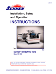
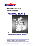
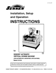
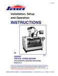
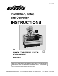
I-MBC-188
New Machine
Inspection and Installation
PROCEDURE
IM
T
N
A
T
R
O
P
for
SUNNEN® PRECISION HONING MACHINE
Model: MBC-1805
READ THE FOLLOWING INSTRUCTIONS THOROUGHLY AND CAREFULLY BEFORE UNPACKING,
INSPECTING, OR INSTALLING THE SUNNEN® PRECISION HONING MACHINE.
“SUNNEN AND THE SUNNEN LOGO ARE REGISTERED TRADEMARKS OF SUNNEN PRODUCTS COMPANY.”
SUNNEN ® PRODUCTS COMPANY • 7910 MANCHESTER ROAD • ST. LOUIS, MO 63143, U.S.A. • PHONE: 314-781-2100
GENERAL INFORMATION
The Sunnen® equipment has been designed and engineered for a wide variety of parts within the capacity and limitation of the equipment. With proper care
and maintenance this equipment will give years of service.
READ THE FOLLOWING INSTRUCTIONS CAREFULLY AND THOROUGHLY BEFORE UNPACKING, INSPECTING, OR INSTALLING THIS EQUIPMENT.
IMPORTANT: Read any supplemental instructions BEFORE installing this equipment. These supplemental instructions give you important information to
assist you with the planning and installation of your Sunnen equipment.
Sunnen Technical Service Department is available to provide telephone assistance for installation, programming, & troubleshooting of your Sunnen
equipment. All support is available during normal business hours, 8:00 AM to 4:30 PM Central Time.
Review all literature provided with your Sunnen equipment. This literature provides valuable information for proper installation, operation, and maintenance
of your equipment. Troubleshooting information can also be found within the Instructions. If you cannot find what you need, call for technical support.
Where applicable, programming information for your Sunnen equipment is also included. Most answers can be found in the literature packaged with your
equipment.
Help us help you. When ordering parts, requesting information, or technical assistance about your equipment, please have the following
information available:
• Have ALL MANUALS on hand. The Customer Services Representative or Technician will refer to it.
• Have Model Number and Serial Number printed on your equipment Specification Nameplate.
• Where Applicable: Have Drive model and all nameplate data. Motor type, brand, and all nameplate data.
For Troubleshooting, additional information may be required:
• Power distribution information (type - delta, wye, power factor correction; other major switching devices used, voltage fluctuations)
• Installation Wiring (separation of power & control wire; wire type/class used, distance between drive and motor, grounding).
• Use of any optional devices/equipment between the Drive & motor (output chokes, etc.).
For fast service on your orders call:
Sunnen Automotive Customer Service toll free at: 1-800-772-2878
Sunnen Industrial Customer Service toll free at: 1-800-325-3670
Customers outside the USA, contact your local authorized Sunnen Distributor.
Additional information available at: http://www.sunnen.com or e-mail: [email protected]
NOTE: Sunnen reserves the right to change or revise specifications and product design in connection with any feature of our products contained herein.
Such changes do not entitle the buyer to corresponding changes, improvements, additions, or replacements for equipment, supplies or accessories
previously sold. Information contained herein is considered to be accurate based on available information at the time of printing. Should any discrepancy of
information arise, Sunnen recommends that user verify the discrepancy with Sunnen before proceeding.
ESD PREVENTION REVIEW
Let's review the basics of a sound static control system and its effective implementation. First, in the three step plan:
1.
Always ground yourself when handling sensitive components or assemblies.
2.
Always use a conductive or shielded container during storage or transportation. These materials create a Faraday
cage which will isolate the contents from static charges.
3.
Open ESD safe containers only at a static safe work station.
At the static safe work station, follow these procedures before beginning any work:
A.
Put on your wrist strap or foot grounding devices.
B.
Check all grounding cords to make sure they are properly connected to ground, ensuring the effective dissipation of static charges.
C.
Make sure that your work surface is clean and clear of unnecessary materials, particularly common plastics.
D.
Anti-static bubble wrap has been included for use at the machine when an ESD safe workstation is not available.
You are now properly grounded and ready to begin work. Following these few simple rules and using a little common sense will go a long
way toward helping you and your company in the battle against the hazards of static electricity. When you are working with ESD sensitive devices, make sure you:
GROUND
ISOLATE
NEUTRALIZE
SUNNEN® LIMITED PRODUCT WARRANTY
Sunnen® Products Company and its subsidiaries (SPC) warrant that all new SPC honing machines, gaging equipment, tooling, and related equipment will
be free of defects in material and/or workmanship for a period of one year from the date of original shipment from SPC.
Upon prompt notification of a defect during the one-year period, SPC will repair, replace, or refund the purchase price, with respect to parts that prove to be
defective (as defined above). Any equipment or tooling which is found to be defective from improper use will be returned at the customer's cost or repaired
(if possible) at customer's request. Customer shall be charged current rates for all such repair.
Prior to returning any SPC product, an authorization (RMA#) and shipping instructions must be obtained from the Customer Service Department or items
sent to SPC will be returned to the customer.
Warranty Limitations and Exclusions This Warranty does not apply to the following:
• Normal maintenance items subject to wear and tear: (belts, fuses, filters, etc).
• Damages resulting from but not limited to:
› Shipment to the customer (for items delivered to customer or customer's agent F.O.B., Shipping Point)
› Incorrect installation including improper lifting, dropping and/or placement
› Incorrect electric power (beyond +/- 10% of rated voltage) including intermittent or random voltage spikes or drops
› Incorrect air supply volume and/or pressure and/or contaminated air supply
› Electromagnetic or radio frequency interference from surrounding equipment (EMI, RFI)
› Storm, lightning, flood or fire damage
› Failure to perform regular maintenance as outlined in SPC manuals
› Improper machine setup or operation causing a crash to occur
› Misapplication of the equipment
› Use of non-SPC machines, tooling, abrasive, fixturing, coolant, repair parts, or filtration
› Incorrect software installation and/or misuse
› Non-authorized customer installed electronics and/or software
› Customer modifications to SPC software
THE LIMITED WARRANTY DESCRIBED HEREIN IS EXPRESSLY IN LIEU OF ALL ANY OTHER WARRANTIES. SPC MAKES NO REPRESENTATION OR WARRANTY OF ANY
OTHER KIND, EXPRESS OR IMPLIED, WHETHER AS TO MERCHANTABILITY, FITNESS FOR A PARTICULAR PURPOSE OR ANY OTHER MATTER. SPC IS NOT
RESPONSIBLE FOR THE IMPROPER USE OF ANY OF ITS PRODUCTS. SPC SHALL NOT BE LIABLE FOR DIRECT, INDIRECT, INCIDENTAL, OR CONSEQUENTIAL
DAMAGES INCLUDING BUT NOT LIMITED TO: LOSS OF USE, REVENUE, OR PROFIT. SPC ASSUMES NO LIABILITY FOR PURCHASED ITEMS PRODUCED BY OTHER
MANUFACTURERS WHO EXTEND SEPARATE WARRANTIES. REGARDLESS OF ANY RIGHTS AFFORDED BY LAW TO BUYER, SPC's LIABILITY, IF ANY, FOR ANY AND
ALL CLAIMS FOR LOSS OR DAMAGES WITH RESPECT TO THE PRODUCTS, AND BUYER'S SOLE AND EXCLUSIVE REMEDY THEREFORE, SHALL IN ALL EVENTS BE
LIMITED IN AMOUNT TO THE PURCHASE PRICE OF THAT PORTION OF THE PRODUCTS WITH RESPECT TO WHICH A VALID CLAIM IS MADE.
Shipping Damages
Except in the case of F.O.B., Buyer's destination shipments, SPC will not be liable for any settlement claims for obvious and/or concealed shipping damages.
The customer bears the responsibility to unpack all shipments immediately and inspect for damage. When obvious and/or concealed damage is found, the
customer must immediately notify the carrier's agent to make an inspection and file a claim. The customer should retain the shipping container and packing
material.
SUNNEN® SOFTWARE LICENSE AGREEMENT
This document is a Legal Agreement between you, as user and licensee (Licensee), and Sunnen® Products Company (SPC) with respect to preprogrammed
software (Software) provided by SPC for use on SPC Equipment. By using the Software, you, as Licensee, agree to become bound by the terms of this
Agreement.
In consideration of payment of the license fee (License Fee) which is part of the price evidenced by your receipt (Receipt), SPC grants to you as Licensee
a non-exclusive right, without right to sub-license, to use the particular copy of the SPC Software licensed hereunder only on the particular equipment sold with
the Software. SPC reserves all rights including rights not otherwise expressly granted, and retain title and ownership to the Software including all subsequent copies or updates in any media. The Software and all accompanying written materials are covered by copyrights owned by SPC. If supplied on
removable media (floppy disk), you, as Licensee, may copy the Software only for back up purposes; or you may request that SPC copy the Software for you
for the same purposes. All other copying of the Software or of the accompanying written materials is expressly forbidden and is in violation of the Agreement.
The Software and accompanying written materials (including the user's manual, if any) are provided in an "as is" condition without warranty of any kind
including the implied warranties of merchantability and fitness for a particular purpose, even if SPC has been advised of this purpose. SPC specifically does
not warrant that it will be liable as a result of the operation of the Software for any direct, indirect, consequential or accidental damages arising out of the
use of or inability to use such product even if SPC has been advised of the possibility of such use. It is recognized that some states do not allow the exclusion or limitation of liability for consequential or accidental damages and to the extent this is true, the above limitations may not apply.
Any alteration or reverse engineering of the software is expressly forbidden and is in violation of this agreement.
SPC reserves the right to update the software covered by this agreement at any time without prior notice and any such updates are covered by this
agreement.
SAFETY INSTRUCTIONS
READ FIRST
This machine, like any equipment, may be dangerous if used improperly. Please
read all warnings and instructions before attempting to use this machine.
Always disconnect power at main enclosure before servicing machine.1
Always wear eye protection when operating this machine.
WARNING: Do not wear cotton or heavy gloves while operating this equipment! If
gloves must be worn, wear only the tear-away type.
NEVER open or remove any machine cover or protective guard with power "ON."
Always disconnect power at main enclosure before servicing this equipment.1
DO NOT attempt any repair or maintenance procedure beyond those described in
this book. Contact your Sunnen® Field Service Engineer or Technical Services
Representative for repairs not covered in these instructions.
Due to the wide variety of machine configurations, all possibilities cannot be
described in these instructions. Instructions for safe use and maintenance of
optional equipment ordered through Sunnen, will be provided through separate
documentation and/or training provided by your Sunnen Field Service Engineer or
Technical Services Representative.
DO NOT attempt to defeat any safety device on this machine or on any of the
optional equipment.
If specially built automation components are added to this system, be sure that
safety is not compromised. If necessary, obtain special enlarged work area safety
system from Sunnen Products Co.
Indicates CE version ONLY.
1
DO NOT touch electrical components until main input power has been turned off and CHARGE
lamps are extinguished. WARNING: The capacitors are still charged and can be quite dangerous.
Important information to assist you with
the unpacking and installation of your
Sunnen Vertical Honing System.
NEW MACHINE
INSPECTION & INSTALLATION PROCEDURE
FOR SUNNEN® PRECISION HONING MACHINE
PURPOSE
TOOLS & MATERIALS
Consult this section when unpacking, inspecting,
and installing Sunnen® MBC-1805 Precision Honing
Machine. Hereafter, referred to as the Machine (see
Figure 1).
The following tools and materials are required for
unpacking and installing the machine:
Knife Hammer
Crow Bar
Tin Snips
Hex Wrench Wire Cutters/Strippers
Screwdriver (Std. Nose)
Slip-Joint Pliers
Open End Wrenches Cleaning Solvent
INSTALLATION
Read the following instructions carefully and
thoroughly before unpacking, inspecting and installing
your Machine. All references to right and left in these
instructions are, unless otherwise noted, as seen by
the operator as one looks at the front of the Machine
or assembly being described (refer to Figure 1).
1. Remove top and front of shipping carton by
cutting along edges.
2. Remove items shipped inside carton.
3. Remove machine from carton and inspect
Machine and Components for dents, scratches, or
damage resulting from improper handling, by
carrier (see Figure 2). If damage is evident,
immediately file a claim with carrier.
LEFT
RIGHT
4. Move Machine to desired location.
5. Level Machine in both left to right and front to
back directions (see Figure 3).
FRONT
FIGURE 1, Precision Honing Machine
LEVELING
BOLTS
FIGURE 2, Unpacking
FIGURE 3, Leveling Machine
1
NOTE: For permanent installation, secure Machine's
Support Feet to floor with four (4) Fasteners.
OIL RESERVOIR
1/4 IN. SCREW
6. Open access Door on front of the Machine.
RESERVOIR
RETAINER
7. Remove Reservoir Retainers, by removing two
(2) Screws (see Figure 1-4).
8. Remove and discard cardboard packing.
9. Open left Belt Guard
10. Open access Door to Filter Canister.
DRAIN
PLUG
SETTLEMENT
TRAY
11. Loosen Screws in Mounting Bracket and raise
Filter Canister Assembly 115 mm (4.5 in.) so hoses
will clear Coolant Reservoir and allow Coolant
Reservoir to be pulled out (see Figure 1-5).
FIGURE 1-4, Coolant Reservoir
CLAMP
12. Tighten Screws in Mounting Bracket.
13. Push Drain Pipe to the left and up.
(190 mm)
14. Pull Reservoir out far enough to remove all
packing paper and tape from the reservoir.
7!s IN.
(300 mm)
15. Remove packing material and tape from the
Settlement Tray, and install tray in Coolant Reservoir.
(115 mm)
4!s IN.
16. Push the Reservoir all the way in and reinstall
Reservoir Retainers, using two (2) Screws removed
in step 7.
MOUNTING
BRACKET
OIL
RESERVOIR
17. Pull Drain Pipe down and to the right.
18. Loosen Screws in Mounting Bracket and lower
Filter Canister Assembly back into operating position.
Tighten Screws.
CLAMP
19. Close access Door to Filter.
20. Close Belt Cover Guard.
(190 mm)
7.5 in.
21. Open access Door to Power Stroke Unit, remove
strapping from Power Stroke Motor; then close Door.
22. WORK TRAY. Install Work Tray on left side of
machine as follows (see Figure 1-6):
Remove Nuts on left side of machine.
Install Work Tray using Nuts just removed.
Install Tray Pad in Work Tray.
MOUNTING
BRACKET
OIL
RESERVOIR
23. DRIP TRAY. Install Drip Tray on right side of
machine as follows (see Figure 1-7):
Remove Nuts on bottom of Operator Control Station.
Install Drip Tray using Nuts just removed.
Install Tray Pad in Drip Tray.
Slide Retaining Bushing over end of Drain Tube
and insert tube into hole in Machine Tray. Allow
13 mm (.500 in.) of Drain Tube to project through
side of Machine Tray. Secure Drain Tube by inserting
Retaining Bushing into hole
Attach other end of Drain Tube to Drip Tray.
24.
12 IN.
}
OPERATING
POSITION
FIGURE 1-5, Filter Canister
LEFT
WORK TRAY
NUT
Raise the work area cover.
FIGURE 1-6, Left Work Tray
2
OPERATOR
CONTROL
PANEL
25. MOVEABLE TRAY. Adjust Moveable Tray as
follows: Lift and pull out the Moveable Tray to a
position that will be comfortable for the job to be
honed.
TRAY PAD
26. AUTOMATIC SIZE CONTROL UNIT. Remove
packing material and tape from the Automatic Size
Control (ASC) Unit (see Figure 1-8), and attach unit
to bracket in Movable Tray.
27.
Close work area cover.
28.
WORK AREA COVER. Loosen the two
Knobs on the top of the cover and move the cover
out until the Target Piece on the cover is over the
Magnetic Switch on the Front Splash Gate (see
Figure 1-9). Tighten the knobs.
Adjust the Pressure Regulator on the Cover
Counterbalance Cylinder so that the Cover will
remain in any position in which it is placed.
DRAIN TUBE
DRIP TRAY
FIGURE 1-7, Right Drip Tray
29.
FOOT PEDAL. To install Foot Pedal
Assembly, proceed as follows (see Figure 1-10).
PROBE BODY
NOTE: DO NOT attempt to fork machine with the
Pedal Tube Assembly and Pedal Assembly installed.
FIGURE 1-8, Automatic Size Control Unit
• Loosen Socket Head Screw (1/4 in. Hex Wrench)
securing Extension Bar to Cross Bar, and slide
Extension Bar out of Cross Bar.
• Slide Cross Bar under machine so U-Shade Hook on
end of Bar engages Machine’s Foot Pedal Extension
Bars. Slide Bar in at an angle; engage one side, then
straighten out Bar to engage other side.
• Slide Cross Bar back and hook over Machine’s
Cross Arm.
• Remove Foot Pedal from Accesory Pack.
• Lay Foot Pedal Assembly (Extension Bar) on its side.
• Slide Foot Pedal over Cross Arm on Extension Bar
and tighten Socket Head Screw (1/4 in. Hex
Wrench).
• Slide Extension Bar into Cross Bar and tighten
Socket Head Screw (1/4 in. Hex Wrench).
FIGURE 1-9, Work Area Cover
EXTENSION
BARS
CROSS
ARM
HOOK
CROSS
BAR
CROSS
BAR
AIRLINE
SCREW
FITTING
EXTENSION
BAR
EXTENSION
BAR
PEDAL ASSSEMBLY ON
ITS SIDE
SCREW
EXTENSION
BAR
PEDAL
ASSEMBLY
FIGURE 1-11, AIR FILTER REGULATOR
FIGURE 1-10, Pedal Assembly
3
30. Open access Door on top right of the machine.
NOTE:
machines require no tools to open doors.
31. Route a 6,350mm (1/4") air supply line (Parker
Push Lok-801-4 Air Line or its equivalent is recommended) under back panel of machine and up to
Barb Fitting on Inlet Side of Air Filter/Regulator
(see Figure 1-11).
(90
MAIN POWER
DISCONNECT
NOTE: An air supply of at least 5.5 Bar (80 psi)
must be connected to machine for Automatic Cycle
Start to operate properly.
32. Route Drain Hose to Coolant Reservoir.
m
(23
3
m)
0m
.5
9
m)
IN
.
IN.
OKAY
HERE
NOT
HERE
OKAY
HERE
33 Close access Door.
(76
ELECTRICAL CONNECTION
)
mm
3I
N.
OKAY
HERE
The 230 V Machine requires a 5,3mm2 (#10/4, Type
SO, 600 Volts) electrical supply cord. (The Machine
requires 230 V, 3 Phase, 50 or 60 Cycle Power.
Maximum current load is 35 amps.)
The 460 V Machine requires a 3,3mm2 (#12/4, Type
SO, 600 Volts) electrical supply cord. (The Machine
requires 460 V, 3 Phase, 50 or 60 Cycle Power.
Maximum current load is 35 amps.)
(76
m
3
m)
IN
.
PREFERRED
AREA
WIRES:
RED
WHT
BLK
GROUND
WIRE:
GRN
1. Loosen Safety Latches on Electrical Control,
and remove padlock if installed.
ELECTRICAL
DISCONNECT
BLOCK
2. Turn OFF Main Power Disconnect and open
door to enclosure.
3. Punch a 22mm (.875") Diameter Hole through
the bottom of Enclosure (see Figure 1-12).
ELECTRICAL
SUPPLY
CORD
4. Insert Electrical Supply Cord through Entrance
Hole, using a Cord Connector (not supplied) to
provide an oil tight fitting. Allow for approximately
610mm (24") of cable from where it enters
enclosure and cut off excess.
OIL TIGHT
FITTING
FIGURE 1-12 Electrical Control Enclosure
5. Strip 250mm (10 in.) of outer jacket from cable.
6. Strip 10mm (.375 in.) of insulation from each wire.
7. Connect green wire (electrical supply cord) to
Terminal E or PE (Earth Ground).
8. Connect other three wires (electrical supply
cord) to top of Electrical Disconnect Block as noted
on block.
1/4 IN. SCREW
9. Replace plastic cover on Electrical Disconnect
Block. 10. Close and lock door to Electrical Control
Enclosure.
RESERVOIR
RETAINER
OIL RESERVOIR
11. Connect Electrical Supply Cord to power source.
12. Turn ON power at Main Power Disconnect and
check spindle shaft rotation.
NOTE: Rotation of Spindle Shaft should be
counterclockwise, as viewed from output end of
Spindle Drive Motor. If rotation is incorrect reverse
any two wires, connected in step 8.
13. Turn OFF power.
SETTLEMENT
TRAY
DRAIN
PLUG
FIGURE 1-13, Coolant Reservoir
4
FILLING FLUIDS
1. Power up the Machine and check that motors
and spindle are operating properly.
Fill Coolant Reservoir with Sunnen Industrial Honing
Oil or Sunnen Water-Based Coolant as follows (see
Figure 1-13):
2. Bleed Coolant System:
Direct Coolant Nozzles downward and open Knobs
on Flow Control Manifold.
Turn ON power and let pump run until all coolant
nozzles are delivering a steady stream of coolant.
Pour an additional 19 liters (5 gallons) of approved
coolant into the Machine Work Tray, to top off the
system as the Filter Canister fills. The Coolant
System holds a total of 106 liters (28 gallons) of
coolant.
Push POWER OFF Button.
NOTE: Maximum capacity of the Coolant Reservoir
is 106 liters (28 gallons). A minimum capacity of 38
liters (10 gallons) is needed for proper pump
operation.
1. Open Door on front of Machine.
2. Remove Settlement Tray from Coolant Reservoir.
3. Pour approximately 90 liters (23 gallons) of
coolant into the machine Work Tray or pump
coolant directly into Reservoir.
3. After unpacking and installing the Machine,
clean and lubricate. Refer to Section 4.
4. Replace Tray and close door.
OPERATIONAL CHECK
Read Sections 2 and 3 thoroughly and carefully
before performing the Operational Check.
5
NOTES
CAUTION
IT IS NOT RECOMMENDED THAT GLOVES BE
WORN WHILE OPERATING THIS EQUIPMENT!
HOWEVER, IF GLOVES ARE WORN, WEAR
ONLY LATEX GLOVES THAT CAN EASILY
RIP IF CAUGHT ON A ROTATING MANDREL.
6
NEW MACHINE
INSPECTION & INSTALLATION PROCEDURE
CHECKLIST
FOR SUNNEN® MODULAR HONING SYSTEM
MECHANICAL
1.
2.
3.
4.
5.
6.
7.
8.
9.
10.
11.
12.
13.
14.
ELECTRICAL
Move machine to staging area.
Remove shipping carton.
Remove all loose components.
Check components against list.
Inspect Machine and components.
Remove Bolts securing Machine to Skid.
Lift Machine and install Adjustable Feet.
1. Open doors to enclosure.
2. Route cables and connect to enclosure.
3. Attach power cord.
4. Route and connect cord to power source.
5. Visual check cable connectors.
6. Close doors to enclosure.
7. Connect coolant system to power source.
Move machine to desired location.
GENERAL
Level machine.
Attach cable track.
Remove wooden block.
Attach coolant system.
Visual check hoses.
Verify all guards are in place.
!
WARNING
1. Fill grease lubricating system.
2. Connect coolant system supply hose.
3. Connect coolant system return hose.
4. Fill coolant system reservoir.
5. Perform operational check.
!
DO NOT WEAR COTTON
OR HEAVY GLOVES
WHILE OPERATING
THIS EQUIPMENT!
IL1198 / PNP520
Like any machinery, this equipment may
be dangerous if used improperly. Be sure
to read and follow instructions for
operation of equipment.
7
FRACTION / DECIMAL / MILLIMETER EQUIVALENTS CHART
INCH
FRACTION
DECIMAL
MILLIMETER
INCH
FRACTION
DECIMAL
MILLIMETER
INCH
FRACTION
DECIMAL
MILLIMETER
....
.003937
0,1000
9/32
.281250
7,1438
21/32
.656250
16,6688
....
.007874
0,2000
19/64
.296875
7,5406
....
.669291
17,0000
....
.011811
0,3000
5/16
.312500
7,9375
43/64
.671875
17,0656
1/64
.015625
0,3969
....
.314961
8,0000
11/16
.687500
17,4625
....
.015748
0,4000
21/64
.328125
8,3344
45/64
.703125
17,8594
....
.019685
0,5000
11/32
.343750
8,7313
....
.708661
18,0000
....
.023622
0,6000
....
.354331
9,0000
23/32
.718750
18,2563
....
.027559
0,7000
23/64
.359375
9,1281
47/64
.734375
18,6531
1/32
.031250
0,7938
3/8
.375000
9,5250
....
.748031
19,0000
....
.031496
0,8000
25/64
.390625
9,9219
3/4
.750000
19,0500
....
.035433
0,9000
....
.393701
10,0000
49/64
.765625
19,4469
....
.039370
1,0000
13/32
.406250
10,3188
25/32
.781250
19,8438
3/64
.046875
1,1906
27/64
.421875
10,7156
....
.787402
20,0000
1/16
.062500
1,5875
....
.433071
11,0000
51/64
.796875
20,2406
5/64
.078125
1,9844
7/16
.437500
11,1125
13/16
.812500
20,6375
....
.078740
2,0000
29/64
.453125
11,5094
....
.826772
21,0000
3/32
.093750
2,3813
15/32
.468750
11,9063
53/64
.828125
21,0344
7/64
.109375
2,7781
....
.472441
12,0000
27/32
.843750
21,4313
....
.118110
3,0000
31/64
.484375
12,3031
55/64
.859375
21,8281
1/8
.125000
3,1750
1/2
.500000
12,7000
....
.866142
22,0000
9/64
.140625
3,5719
....
.511811
13,0000
7/8
.875000
22,2250
5/32
.156250
3,9688
33/64
.515625
13,0969
57/64
.890625
22,6219
....
.157480
4,0000
17/32
.531250
13,4938
....
.905512
23,0000
11/64
.171875
4,3656
35/64
.546875
13,8906
29/32
.906250
23,0188
3/16
.187500
4,7625
....
.551181
14,0000
59/64
.921875
23,4156
....
.196850
5,0000
9/16
.562500
14,2875
15/16
.937500
23,8125
13/64
.203125
5,1594
37/64
.578125
14,6844
....
.944882
24,0000
7/32
.218750
5,5563
....
.590551
15,0000
61/64
.953125
24,2094
15/64
.234375
5,9531
19/32
.593750
15,0813
31/32
.968750
24,6063
....
.236220
6,0000
39/64
.609375
15,4781
....
.984252
25,0000
1/4
.250000
6,3500
5/8
.625000
15,8750
63/64
.984375
25,0031
17/64
.265625
6,7469
....
.629921
16,0000
1
1.000000
25,4000
....
.275591
7,0000
41/64
.640625
16,2719
1-1/16
1.062500
26,9880
FORMULAS:
MULTIPLY
INCHES (in)
FEET (ft)
x
x
BY
25.4
0.3048
=
=
TO GET
MILLIMETERS (mm)
METERS (m)
MULTIPLY
MILLIMETERS (mm)
METERS (m)
x
x
BY
0.03937
3.281
=
=
TO GET
INCHES (in)
FEET (ft)
“SUNNEN AND THE SUNNEN LOGO ARE REGISTERED TRADEMARKS OF SUNNEN PRODUCTS COMPANY.”
Sunnen® reserves the right to change or
revise specifications and product design
in connection with any feature of our
products contained herein. Such changes
do not entitle the buyer to corresponding
changes, improvements, additions, or
replacements for equipment, supplies or
accessories previously sold. Information
contained herein is considered to be
accurate based on available information
at the time of printing. Should any
discrepancy of information arise, Sunnen
recommends that user verify discrepancy
with Sunnen before proceeding.
PRINTED IN U.S.A.
0803
SUNNEN PRODUCTS LIMITED
No. 1 Centro, Maxted Road
Hemel Hempstead, Herts HP2 7EF ENGLAND
Phone: ++ 44 1442 39 39 39
Fax: ++ 44 1442 39 12 12
www.sunnen.co.uk
e-mail: [email protected]
SUNNEN AG
SUNNEN PRODUCTS COMPANY
7910 Manchester Road, St. Louis, MO 63143 U.S.A.
Phone: 314-781-2100
Fax: 314-781-2268
U.S.A. Toll-Free Sales and Service –
Automotive: 1-800-772-2878 • Industrial: 1-800-325-3670
International Division Fax: 314-781-6128
Fabrikstrasse 1
8586 Ennetaach-Erlen, Switzerland
Phone: ++ 41 71 649 33 33
Fax: ++ 41 71 649 34 34
www.sunnen.ch
e-mail: [email protected]
SHANGHAI SUNNEN MECHANICAL CO., LTD.
889 Kang Qiao East Road, PuDong
Shanghai 201319, P.R. China
Phone: 86 21 5 813 3322
Fax: 86 21 5 813 2299
www.sunnensh.com
e-mail: [email protected]
SUNNEN ITALIA S.R.L.
http://www.sunnen.com
e-mail: [email protected]
Viale Stelvio 12/15
20021 Ospiate di Bollate (MI) Italy
Phone: 39 02 383 417 1
Fax: 39 02 383 417 50
www.sunnenitalia.com
e-mail: [email protected]
©COPYRIGHT SUNNEN® PRODUCTS COMPANY 2008, ALL RIGHTS RESERVED