1
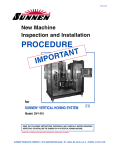
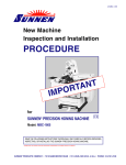
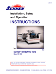
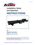
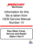
I-PF-157
New Machine
Inspection and Installation
PROCEDURE
IM
T
N
A
T
R
PO
THESE INSTRUCTIONS COVERS
THE PF-150 BEGINNING WITH
SERIAL No. 3485 (1pH) /10382 (3pH).
for
SUNNEN® FILTRATION UNIT
Model: PF-150
READ THE FOLLOWING INSTRUCTIONS THOROUGHLY AND CAREFULLY BEFORE UNPACKING,
INSPECTING, OR INSTALLING THE SUNNEN® PF-150 FILTRATION UNIT.
“SUNNEN® AND THE SUNNEN LOGO ARE REGISTERED TRADEMARKS OF SUNNEN PRODUCTS COMPANY.”
SUNNEN ® PRODUCTS COMPANY • 7910 MANCHESTER ROAD • ST. LOUIS, MO 63143, U.S.A. • PHONE: 314-781-2100
GENERAL INFORMATION
The Sunnen® equipment has been designed and engineered for a wide variety of parts within the capacity and limitation of the equipment. With proper care
and maintenance this equipment will give years of service.
READ THE FOLLOWING INSTRUCTIONS CAREFULLY AND THOROUGHLY BEFORE UNPACKING, INSPECTING, OR INSTALLING THIS EQUIPMENT.
IMPORTANT: Read any supplemental instructions BEFORE installing this equipment. These supplemental instructions give you important information to
assist you with the planning and installation of your Sunnen equipment.
Sunnen Technical Service Department is available to provide telephone assistance for installation, programming, & troubleshooting of your Sunnen
equipment. All support is available during normal business hours, 8:00 AM to 4:30 PM Central Time. Emergency breakdown support is available on a 24
hour / 7 day basis.
Review all literature provided with your Sunnen equipment. This literature provides valuable information for proper installation, operation, and maintenance
of your equipment. Troubleshooting information can also be found within the Instructions. If you cannot find what you need, call for technical support.
Where applicable, programming information for your Sunnen equipment is also included. Most answers can be found in the literature packaged with your
equipment.
Help us help you. When ordering parts, requesting information, or technical assistance about your equipment, please have the following
information available:
• Have ALL MANUALS on hand. The Customer Services Representative or Technician will refer to it.
• Have Model Number and Serial Number printed on your equipment Specification Nameplate.
• Where Applicable: Have Drive model and all nameplate data. Motor type, brand, and all nameplate data.
For Troubleshooting, additional information may be required:
• Power distribution information (type - delta, wye, power factor correction; other major switching devices used, voltage fluctuations)
• Installation Wiring (separation of power & control wire; wire type/class used, distance between drive and motor, grounding).
• Use of any optional devices/equipment between the Drive & motor (output chokes, etc.).
For fast service on your orders call:
Sunnen Automotive Customer Service toll free at: 1-800-772-2878
Sunnen Industrial Customer Service toll free at: 1-800-325-3670
Customers outside the USA, contact your local authorized Sunnen Distributor.
Additional information available at: http://www.sunnen.com or e-mail: [email protected]
NOTE: Sunnen reserves the right to change or revise specifications and product design in connection with any feature of our products contained herein.
Such changes do not entitle the buyer to corresponding changes, improvements, additions, or replacements for equipment, supplies or accessories
previously sold. Information contained herein is considered to be accurate based on available information at the time of printing. Should any discrepancy of
information arise, Sunnen recommends that user verify the discrepancy with Sunnen before proceeding.
ESD PREVENTION REVIEW
Let's review the basics of a sound static control system and its effective implementation. First, in the three step plan:
1.
Always ground yourself when handling sensitive components or assemblies.
2.
Always use a conductive or shielded container during storage or transportation. These materials create a Faraday
cage which will isolate the contents from static charges.
3.
Open ESD safe containers only at a static safe work station.
At the static safe work station, follow these procedures before beginning any work:
A.
Put on your wrist strap or foot grounding devices.
B.
Check all grounding cords to make sure they are properly connected to ground, ensuring the effective dissipation of static charges.
C.
Make sure that your work surface is clean and clear of unnecessary materials, particularly common plastics.
D.
Anti-static bubble wrap has been included for use at the machine when an ESD safe workstation is not available.
You are now properly grounded and ready to begin work. Following these few simple rules and using a little common sense will go a long
way toward helping you and your company in the battle against the hazards of static electricity. When you are working with ESD sensitive devices, make sure you:
GROUND
ISOLATE
NEUTRALIZE
ii
SUNNEN® LIMITED PRODUCT WARRANTY
Sunnen® Products Company and its subsidiaries (SPC) warrant that all new SPC honing machines, gaging equipment, tooling, and related equipment will
be free of defects in material and/or workmanship for a period of one year from the date of original shipment from SPC.
Upon prompt notification of a defect during the one-year period, SPC will repair, replace, or refund the purchase price, with respect to parts that prove to be
defective (as defined above). Any equipment or tooling which is found to be defective from improper use will be returned at the customer's cost or repaired
(if possible) at customer's request. Customer shall be charged current rates for all such repair.
Prior to returning any SPC product, an authorization (RMA#) and shipping instructions must be obtained from the Customer Service Department or items
sent to SPC will be returned to the customer.
Warranty Limitations and Exclusions This Warranty does not apply to the following:
• Normal maintenance items subject to wear and tear: (belts, fuses, filters, etc).
• Damages resulting from but not limited to:
› Shipment to the customer (for items delivered to customer or customer's agent F.O.B., Shipping Point)
› Incorrect installation including improper lifting, dropping and/or placement
› Incorrect electric power (beyond +/- 10% of rated voltage) including intermittent or random voltage spikes or drops
› Incorrect air supply volume and/or pressure and/or contaminated air supply
› Electromagnetic or radio frequency interference from surrounding equipment (EMI, RFI)
› Storm, lightning, flood or fire damage
› Failure to perform regular maintenance as outlined in SPC manuals
› Improper machine setup or operation causing a crash to occur
› Misapplication of the equipment
› Use of non-SPC machines, tooling, abrasive, fixturing, coolant, repair parts, or filtration
› Incorrect software installation and/or misuse
› Non-authorized customer installed electronics and/or software
› Customer modifications to SPC software
THE LIMITED WARRANTY DESCRIBED HEREIN IS EXPRESSLY IN LIEU OF ALL ANY OTHER WARRANTIES. SPC MAKES NO REPRESENTATION OR WARRANTY OF ANY
OTHER KIND, EXPRESS OR IMPLIED, WHETHER AS TO MERCHANTABILITY, FITNESS FOR A PARTICULAR PURPOSE OR ANY OTHER MATTER. SPC IS NOT
RESPONSIBLE FOR THE IMPROPER USE OF ANY OF ITS PRODUCTS. SPC SHALL NOT BE LIABLE FOR DIRECT, INDIRECT, INCIDENTAL, OR CONSEQUENTIAL
DAMAGES INCLUDING BUT NOT LIMITED TO: LOSS OF USE, REVENUE, OR PROFIT. SPC ASSUMES NO LIABILITY FOR PURCHASED ITEMS PRODUCED BY OTHER
MANUFACTURERS WHO EXTEND SEPARATE WARRANTIES. REGARDLESS OF ANY RIGHTS AFFORDED BY LAW TO BUYER, SPC's LIABILITY, IF ANY, FOR ANY AND
ALL CLAIMS FOR LOSS OR DAMAGES WITH RESPECT TO THE PRODUCTS, AND BUYER'S SOLE AND EXCLUSIVE REMEDY THEREFORE, SHALL IN ALL EVENTS BE
LIMITED IN AMOUNT TO THE PURCHASE PRICE OF THAT PORTION OF THE PRODUCTS WITH RESPECT TO WHICH A VALID CLAIM IS MADE.
Shipping Damages
Except in the case of F.O.B., Buyer's destination shipments, SPC will not be liable for any settlement claims for obvious and/or concealed shipping damages.
The customer bears the responsibility to unpack all shipments immediately and inspect for damage. When obvious and/or concealed damage is found, the
customer must immediately notify the carrier's agent to make an inspection and file a claim. The customer should retain the shipping container and packing
material.
SUNNEN® SOFTWARE LICENSE AGREEMENT
This document is a Legal Agreement between you, as user and licensee (Licensee), and Sunnen® Products Company (SPC) with respect to preprogrammed
software (Software) provided by SPC for use on SPC Equipment. By using the Software, you, as Licensee, agree to become bound by the terms of this
Agreement.
In consideration of payment of the license fee (License Fee) which is part of the price evidenced by your receipt (Receipt), SPC grants to you as Licensee
a non-exclusive right, without right to sub-license, to use the particular copy of the SPC Software licensed hereunder only on the particular equipment sold with
the Software. SPC reserves all rights including rights not otherwise expressly granted, and retain title and ownership to the Software including all subsequent copies or updates in any media. The Software and all accompanying written materials are covered by copyrights owned by SPC. If supplied on
removable media (floppy disk), you, as Licensee, may copy the Software only for back up purposes; or you may request that SPC copy the Software for you
for the same purposes. All other copying of the Software or of the accompanying written materials is expressly forbidden and is in violation of the Agreement.
The Software and accompanying written materials (including the user's manual, if any) are provided in an "as is" condition without warranty of any kind
including the implied warranties of merchantability and fitness for a particular purpose, even if SPC has been advised of this purpose. SPC specifically does
not warrant that it will be liable as a result of the operation of the Software for any direct, indirect, consequential or accidental damages arising out of the
use of or inability to use such product even if SPC has been advised of the possibility of such use. It is recognized that some states do not allow the exclusion or limitation of liability for consequential or accidental damages and to the extent this is true, the above limitations may not apply.
Any alteration or reverse engineering of the software is expressly forbidden and is in violation of this agreement.
SPC reserves the right to update the software covered by this agreement at any time without prior notice and any such updates are covered by this
agreement.
iii
SAFETY INSTRUCTIONS
READ FIRST
This machine, like any machine tool, may be dangerous if used improperly. Please read all
warnings and instructions before attempting to use this machine.1
DO NOT remove or defeat any safety device.
Always wear eye protection when operating this machine.
DO NOT attempt any repair or maintenance procedure beyond those described in this book.
Contact your Sunnen Service Representative for repairs not covered in this book.
Indicates CE version ONLY.
1
DO NOT touch electrical components until main input power has been turned off and CHARGE lamps are
extinguished. WARNING: The capacitors are still charged and can be quite dangerous.
INTRODUCTION
Sunnen PF-150 Filtration Unit is designed to filter grit and metal particles from coolant supply on Sunnen
Precision Honing Machines and other manufacture machines.
Unit is a 100% filter in that it filters all of coolant that passes through it; none is bypassed unless you
intentionally bypass it. In operation, unit's pump sucks dirty coolant from machine reservoir and pushes
this dirty coolant through a 5-micron paper filter element. Clean filtered coolant is then returned to
machine.
Unit pumps an oversupply of filtered coolant to machine. This oversupply of coolant is bled off to machine
reservoir by overflowing receiving bucket or by action of optional low-pressure relief valve (MBB-1620
Pump Bypass Kit), depending upon which method of installation is employed.
As filter canister fills with sludge being removed from coolant, an ample supply of filtered coolant
continues to be supplied to machine. Over 75 cubic inches (1.2 liters) of sludge can accumulate in canister
without interfering with filtering operation. When filter element clogs, coolant supply to machine is shut
off. 5-micron filter element can be changed easily in a few minutes, restoring flow filtered coolant.
Important information to assist you with
the unpacking and installation of your
Sunnen Vertical Honing System.
iv
NEW MACHINE
INSPECTION & INSTALLATION PROCEDURE
FOR SUNNEN® PF150 FILTRATION UNIT
GENERAL
This section is designed to aid in installation of
Sunnen PF-150 FILTRATION Unit.
Unit may be used in either of two ways:
First - Unit can be installed to supply clean coolant
to machine pump without additional adapters or
fittings. Belt-driven pumps will then supply clean
coolant to machine's flow control manifold. (See
Installation.)
Second - Unit may also be installed using optional
MBB-1620 Pump Bypass Kit (not supplied, must be
ordered separately). When unit is installed in this
manner, machine pump is bypassed and clean
FIGURE 1, Unpacking
coolant is supplied directly from Unit to machine's
flow control manifold. advantages of this installation is a stronger, more constant flow of coolant to
workpiece; and a slight increase in power at
machine's spindle, since spindle motor is no longer
operating machine's pump. (See Optional
Installation.)
SUGGESTED TOOLING
The following tools are required for installation:
Knife
Screw Driver (std.)
Hex Wrenches (1/8 & 5/32 in.)
Open End Wrench (7/16 & 9/16 in.)
UNPACKING
Unpack Unit as follows (see Figure1):
1. Cut Bands on shipping carton.
2. Cut around base of outer shipping carton and lift
carton off.
3. Cut down side of inner shipping carton and
remove.
4. Open Unit and remove any contents packaged
inside unit.
5. Open Accessory Pack and inventory contents (see
Figure 2).
6. Remove any Packaging from inside Unit.
7. Inspect Unit and Accessories for signs of damage
resulting from improper handling by carrier. If
damage is evident, immediately file a claim with
carrier and notify Sunnen Customer Service.
CLAMPS
1/2” NIPPLE & ELBOW
(INTAKE HOSE)
(NOT•USED•IN•ALL•APPLICATIONS)
3/8” NIPPLE, ELBOW &
COLLAR
(OUTLET HOSE)
ELBOW &
COLLAR
(SUCTION LINE)
OUTLET HOSE
(PLAIN END)
INTAKE HOSE
(W/STRAINER)
RECEIVING BUCKET
(NOT•USED•IN•ALL•APPLICATIONS)
FIGURE 2, PF-165 Installation Kit
KNOCKOUT
PLUG
INSTALLATION - ML Application
To install Unit on one of Sunnen ML-Series Power
Stroked Honing Machines, proceed as follows:
INTAKE
NOTE: Receiving Bucket IS NOT used when
PF-150 is used with ML-Series Honing Machines.
OUTLET
1. Drain coolant from machine reservoir as
instructed in machine operating instruction book.
2. Turn OFF all power to machine. Unplug electrical
power supply cord or disconnect at main power source.
KNOCKOUT
HOLES
3. Remove reservoir from machine and clean as
instructed in machine operating manual.
FIGURE 3, Knockouts
4. Install Knockout Plugs in two holes in base of
interior wall of reservoir (see Figure 3).
COLLAR
(INTAKE)
5. Elbows and pipe nipple supplied with Kit will be
installed in Holes in left side panel of Reservoir.
ELBOW
(INTAKE)
INTAKE HOSE
W/STRAINER
(SUCTION)
6. Outlet: Apply Permatex No. 2 Sealant (or
equivalent) to 3/8in. Nipple and assemble 3/8in.
Elbows with Collars to machine base as shown (see
Figure 4). Tighten securely to prevent leaks.
Apply Permatex No. 2 Sealant (or equivalent) to
Fitting on end of Outlet Hose. Then connect Hose to
inside Elbow and tighten securely.
7. Intake: Apply Permatex No. 2 Sealant (or
equivalent) to Fitting on end of Intake Hose and
assemble 1/2in. Elbows with Collars to machine base
as shown (refer to Figure 4). Tighten securely to
prevent leaks. Then attach Strainer to end of Intake
Hose with Clamp provided.
8. Slide Reservoir back into machine.
ELBOWS &
COLLAR
(OUTLET)
OUTLET HOSE
OUTLET HOSE
(FROM PF-150)
FIGURE 4, Connections
9. Connect Intake Hose (Dirty Oil) and Outlet Hose
(Filtered Oil) between Filtration Unit and machine
(see Figure 5). Use sealant on all threaded
connections and tighten securely to prevent leaks.
INTAKE HOSE
(SUCTION)
OUTLET HOSE
NOTE: These oil hoses are attached to Unit cabinet
for shipment. Connect hoses to machine first, then to
swivel adapter on Unit cabinet.
10 Open top to Unit and remove cover clamp and
cover.
Insert filter element into container, rotate element
slightly while inserting to make it slide down center
post more easily (see Figure 6).
Replace cover, center carefully on rubber gasket to
assure no leakage. Then replace Clamp and tighten
Hex Bolt in Clamp Halves until halves meet, then
tighten T-Handle.
FIGURE 5, Filtration Unit
T-HANDLE
FILTER
ELEMENT
COVER
AIR VENT
11. Hookup is now complete. Check for proper oil
line routing.
CLAMP HALVES
NOTE: TIGHTEN HEX BOLT
UNTIL CLAMP HALVES MEET,
THEN TIGHTEN T-HANDLE.
12. Make Electrical Connection.
FIGURE 6, Filter Element
2
INSTALLATION - Standard Application
8. Replace oil pump belt and adjust tension as
instructed in machine operating instruction book.
9. If so Equipped: Remove two knockouts from left
side panel of machine base. Elbows and pipe nipples
supplied with Kit will be installed in these Holes
(see Figure 9).
On some early model Sunnen honing machines, and
other manufacturers machines, holes were not
provided in side panel of machine base. With these
machines, locate and drill one 7/ in. (22 mm) diameter Hole and one 3/4in. (19 mm) diameter Hole. If
sheet metal drills or hole saws are not available, use
a piece of wood to back up area being drilled.
On Sunnen honing machines manufactured prior to
1979, both Holes in machine base were 3/4in. (19
mm) diameter. Enlarge Hole nearest back of machine
base to 7/8in. (22 mm) diameter.
10. Apply Permatex No. 2 Sealant, or equal to 3/8in.
Nipples and assemble 3/8in.Elbows with Collars to
machine base (see Figure 10). Tighten securely.
11. Connect Intake Hose (with strainer) to rear
12/in. Elbow. Use sealant on threaded connection
and tighten securely.
To install Unit on one of Sunnen Precision Honing
Machines, proceed as follows:
1. Drain coolant from machine reservoir as
instructed in machine operating instruction book.
2. Turn OFF all power to machine. Unplug electrical
power supply cord or disconnect at main power source.
3. Remove Left Rear Cover of machine base and
remove Oil Pump Belt (see Figure 7).
4. Locate coolant line (tube and spring assembly)
inside machine base that connects oil pump to Flow
control manifold, and disconnect. Do not discard.
5. Clean machine reservoir. Remove reservoir from
machine and clean as instructed in machine
operating manual.
6. Attach Receiving Bucket to pump support (see
Figure 8). Pump Support must engage notches in
front and rear walls of Bucket. Knockout Plug should
face left side of reservoir, as seen when facing front
of machine. DO NOT remove Knockout Plug.
7. Place reservoir back in machine and reconnect
oil line to Flow control manifold.
5 in.
(127mm)
PUMP BELT
SCREW(4)
3 in.
(76mm)
2 in.
(51mm)
1/2” ELBOW (BOTH SIDES)
3/8” ELBOW (BOTH SIDES)
COLLAR
(INSIDE UNIT)
LEFT REAR
COVER
HOLE
7/8in. (22mm)
HOLE
3/4 in. (19mm)
FIGURE 9, Elbows
INSIDE UNIT
FIGURE 7, Oil Pump Belt
OUTLET
HOSE
PUMP
SUPPORT
CLAMPS
RECEIVING
BUCKET
OUTSIDE
UNIT
KNOCKOUT
PLUG
FIGURE 8, Receiving Bucket
INTAKE
HOSE
FIGURE 10, Coolant Lines
3
RECEIVING
BUCKET
12. Connect Outlet Hose (plain end) to forward
3/8in. Elbow. Use sealant on threaded connection
and tighten securely.
13. Loosen clamps on Receiving Bucket. Install
Intake under clamp on outside of Bucket; and install
Outlet Hose under clamp on inside of bucket. Then
tighten clamps.
OUTLET
HOSE
14. Place Unit at left side or in back of machine.
INTAKE
HOSE
15. Connect Intake and Outlet Hoses between Unit
and machine (see Figure 11). Use sealant on all
threaded connections and tighten securely to prevent
leaks.
FIGURE 11, Coolant Lines
NOTE: These oil hoses are attached to Unit cabinet
for shipment. Connect hoses to machine first, then to
swivel adapter on Unit cabinet.
FILTER
ELEMENT
T-HANDLE
COVER
AIR VENT
16. Open top to Unit and remove clamp and cover.
17. Insert Filter Element into container, rotate
element slightly while inserting to make it slide
down center post more easily (see Figure 12).
18. Replace cover, center carefully on rubber gasket
to assure no leakage. Then replace Clamp and tighten
Hex Bolt in Clamp Halves until halves meet, then
tighten T-Handle.
19. Hookup is now complete. Check for proper oil
line routing.
20. Proceed to Electrical Connection.
CLAMP HALVES
NOTE: TIGHTEN HEX BOLT
UNTIL CLAMP HALVES MEET,
THEN TIGHTEN T-HANDLE.
FIGURE 12, Filter Element
PUMP
BELT
SCREW(4)
NOTE: Coolant will be replaced in honing machine
and left rear cover of honing machine base will be
reinstalled during Operational Check.
INSTALLATION - Pump Bypass Kit
LEFT REAR
COVER
Filtration Unit may also be installed using Optional
MBB-1620 Pump Bypass Kit. To install using
optional Kit, proceed as follows:
1. Drain coolant from machine reservoir as
instructed in machine operating instruction book.
2. Turn OFF all power to machine. Unplug
electrical power supply cord or disconnect at main
power source.
3. Remove Left Rear Cover of machine base and
remove Oil Pump Belt (see Figure 13).
4. Locate oil line (tube and spring assembly) inside
machine base that connects pump to Flow control
manifold and. Do not discard.
5. Clean machine reservoir. Remove reservoir from
machine and clean as instructed in machine
operating manual.
6. If so Equipped: Remove two knockouts from left
side panel of machine base. Elbows and pipe nipples
supplied with Kit will be installed in these Holes
(see Figure 14).
FIGURE 13, Oil Pump Belt
5 in. (127mm)
2 in. (51mm)
3 in. (76mm)
HOLE
7/8in. (22mm)
KNOCKOUT
HOLE
3/4 in. (19mm)
FIGURE 14, Knockouts
4
LOW PRESSURE
RELIEF VALVE
On some early model MBB-1650 honing machines,
holes were not provided in side panel of machine
base. With these machines, locate and drill one 7/8in.
(22 mm) diameter Hole and one 3/4in. (19 mm)
diameter Hole. If sheet metal drills or hole saws are
not available, use a piece of wood to back up area
being drilled.
On honing machines manufactured prior to 1979, both
Holes in machine base were 3/4in. (19 mm) diameter.
Enlarge Hole nearest back of machine base to 7/8in.
(22 mm) diameter.
(FRONT
OF UNIT)
3/8” TEE
3/8” ELBOW
(OUTSIDE
OF UNIT)
COLLAR
1/2”
ELBOW
(INSIDE OF UNIT)
7. Apply Permatex No. 2 Sealant, or equal to 1/2in.
Nipple and 3/8in. Elbows (see Figure 15). Install
Nipple, Elbows, and Collar in 7/8in. (22 mm) diameter
Hole as shown. Collar is installed on inside of
machine base. Tighten securely to prevent leaks.
FIGURE 15, Fittings
9. Apply sealant to all threaded connections and
install following items thru 3/4in. (19-mm) diameter
Hole as shown (refer to Figure 15):
3/8" Elbow (PF-165 Installation Kit)
3/8" Close Nipple (PF-165)
Collar (PF-165)
3/8" Tee (MBB-1620 Pump Bypass Kit)
Low-Pressure Relief Valve (MBB-1620)
LEFT REAR
SLASH GUARD
10. Tighten all pipe connections to prevent leaks.
11. Remove Left Rear Splash Guard from machine
(see Figure 16).
FIGURE 16, Guard
12. Loosen Screw and remove Flow Control Manifold
(see Figure 17).
13. Unscrew Pipe from Manifold; then reinstall
Manifold and left rear splash guard on machine (see
Figure 18).
14. Apply sealant to threads on Nipple; then thread
Nipple with Back Check Valve into manifold from
inside machine base (see Figure 19).
FLOW CONTROL
MANIFOLD
15. Screw Hose Barb (supplied) into Low-Pressure
Relief Valve, use sealant on pipe threads (see
Figure 20).
SCREW
FIGURE 17, Manifold
FLOW CONTROL
MANIFOLD
NIPPLE
PIPE
BACK CHECK
VALVE
FIGURE 19, Back Check Valve
FIGURE 18, Manifold
5
16. Screw threaded end of Outlet Hose into Center
Opening of Tee Fitting as shown (refer to Figure 20).
Use sealant on pipe threads. Connect plain end of
this hose to Hose Barb on Back Check. Fasten with
hose clamp.
CENTER OPENING
OF TEE FITTING
OUTLET HOSE
(TO BACK CHECK)
17. Reinstall reservoir in honing machine.
ELBOW
18. Slide Tube and Spring Assembly, removed in
step 4, over hose barb on Low-Pressure Relief Valve
and secure it with a Hose Clamp (see Figure 21).
NOTE: Make sure free end of Tube and Spring
Assembly is in reservoir. Otherwise, coolant will be
pumped onto floor.
LOW PRESSURE
RELIEF VALVE
HOSE BARB
INTAKE HOSE (FROM
RESERVOIR)
FIGURE 20, Low-Pressure Relief Valve
19. Place Unit at left side or in back of machine.
HOSE
CLAMP
20. Connect Intake and Outlet Hoses between Unit
and machine (see Figure 22). Use sealant on all
threaded connections and tighten securely to prevent
leaks.
NOTE: These oil hoses are attached to Unit cabinet
for shipment. Connect hoses to machine first, then to
swivel adapter on Unit cabinet.
21 Open top to Unit and remove cover clamp and
cover.
LOW PRESSURE
RELIEF VALVE
22. Insert filter element into container, rotate
element slightly while inserting to make it slide
down center post more easily (see Figure 23).
TUBE & SPRING
(TO RESERVOIR)
FIGURE 21, Coolant Line
23. Replace cover, center carefully on rubber gasket
to assure no leakage. Then replace cover clamp.
24. Hookup is now complete. Check for proper oil line
routing.
OUTLET
HOSE
26. Proceed to Electrical Connection.
NOTE: Coolant will be replaced in honing machine
and left rear cover of honing machine base will be
reinstalled during Operational Check.
INTAKE
HOSE
ELECTRICAL REQUIREMENTS
All wiring is to be performed by a competent,
Licensed Electrician in accordance with all local,
state, and federal codes and regulations; along with
any special information provided on machine
nameplate or electrical specification plate.
FIGURE 22, Coolant Line
FILTER
ELEMENT
WARNING
All wiring and electrical equipment service should
be performed by authorized personnel ONLY.
FIGURE 23, Filter Element
6
115V UNIT
Outlet for 115 volt unit should look like the following.
230V UNIT
Outlet for 230 volt unit should look like the following.
ADAPTER
GROUNDING
SCREW
PROPER
OUTLET
GROUNDING PIN
GROUNDING PIN
Electrical supply cord is equipped with a grounding
pin. A temporary adapter, may be used to connect
this plug to a 2-pole receptacle, if a properly
grounded outlet is not available. Temporary adapter
should ONLY be used until a properly grounded
outlet can be installed by a qualified electrician.
Green-colored rigid ear, lug, etc., extending from
adapter MUST be connected to a permanent ground,
such as a properly grounded outlet box.
Unit wiring should comply with all local, state,
and federal codes and ordinances.
Electrical supply cord is equipped with a grounding
type plug. Make sure unit is connected to an outlet
having the same configuration as the plug. No
adapter is available or should be used with this unit.
If the unit MUST be reconnected for use on a
different type of electrical circuit, the reconnection
should be made by a qualified electrician.
Unit wiring should comply with all local, state,
and federal codes and ordinances.
FIGURE 24, Electrical Requirements
ELECTRICAL CONNECTION
Wiring is complete on all Filtration Units. Wiring
diagrams are furnished with every unit. Also, each
Unit is shipped with a tag attached that specifies
operating voltage.
NOTE: The electrical data plate attached to Unit
provides helpful data including maximum current
requirements. Wiring diagram number for unit is
stamped on this plate. Should additional copies be
needed, specify DIAGRAM NUMBER with your
request.
CONNECTION
(IN BOTTOM)
115/230 V, 60 Hz, Single Phase Units
These Units are supplied with an electrical cord and
plug that is rated 250 volts, 15 amps. Cord and plug
are generally considered as acceptable
disconnecting means. If required by local code,
disconnect switch, fuses, or circuit breakers must be
provided by user (see Figure 24).
FIGURE 25, Switch Enclosure
CAUTION
Note model electrical supply cord requirement
printed on machine nameplate or electrical
specification plate. Do not attempt to connect
machine if supply voltage is not within following
acceptable limits as noted on nameplate or electrical
specification plate. If supply voltage is not within
these limits MACHINE WILL BE DAMAGED.
230/460 V, 60 Hz, 3pH & 380/440 V, 50 Hz, 3pH
Manual Start Units
Open switch enclosure cover and, with hardware
provided, mount starter switch on Unit cabinet.
Assemble cable connector to switch enclosure as
shown (see Figure 25). Wire cable conductors to
switch as follows:
Red conductor to Terminal TI;
White conductor to Terminal T2;
Black conductor to Terminal T3;
Green conductor to Ground Lug.
Verify supply voltage is same as voltage on Machine
Nameplate or Electrical Specifications Plate.
If supply voltage does not match voltage stated on
Electrical Specification Plate but is within acceptable
limits, electrical connection can proceed but Machine
Conversion below will be necessary.
7
3-phase supply (not furnished) must be brought into
switch enclosure through one of knockouts
provided. Locally approved line disconnect switch
and over current protection (if required) are to be
provided by user. When wiring is complete, reinstall
switch enclosure cover.
(GND) PE
TERMINAL
MASTER
ON/OFF
SWITCH
ELECTRICAL - ML Application
WARNING
All wiring must be performed by a competent
Licensed Electrician in accordance with all local,
state and federal codes and regulations; along with
any special information provided on the machine
nameplate or electrical specification plate.
Verify supply voltage is the same as voltage on
Machine nameplate or Electrical Specification
Plate. Please note some models are sold with an
external transformer that steps down the voltage
to the machine's nameplate voltage. PF-150
nameplate voltage MUST BE THE SAME as
ML-2000 nameplate voltage.
PF150 CORD
CONNECTIONS
NOTE: INSTALL OPT.
FUSEHOLDERS
WHEN USING
PF-150 FILTER UNIT
FIGURE 26, ML-2000 Electrical Connections
Option Installation Kit is required to connect the
PF-150 to the ML-2000.
PF-167C for 230V 60Hz machine or
PF-168C for 400V 50Hz machine
Kit include fuseholder and fuses. The PF-150 is
supplied with a cable that is to be installed into
ML-2000 main electrical enclosure. (Refer to wiring
diagram shipped with PF-167C or PF-168C kits for
electrical connection.)
1. Open door to ML-2000 electrical enclosure.
2. Install Fuseholders (supply with kit) as shown
(see Figure 26).
3. Route cable (supply with kit) into ML-2000
Electrical enclosure and attach wires as shown:
Red Wire (L1) to Fuse (4/5FU1);
White Wire (L2) to Fuse (4/5FU2);
Black Wire (L3) to Fuse (4/5FU3);
Green Wire to Ground Lug (PE).
4. Install fuses (supply with kit) as shown.
INTAKE HOSE
FIGURE 27, Intake Hose
TOTAL VOLUME
CONTROL VALVE
OPERATIONAL CHECK
CAUTION
DO NOT run pump without priming.
1. Fill machine reservoir with Sunnen Industrial
Coolant. Pull out movable tray to its fully extended
position and pour coolant into tray.
FIGURE 28, Total Volume Control Valve
AIR VENT
CAUTION
Make Filtration Unit installation checkout with
honing machine turned off.
FILTER
COVER
COVER
CLAMP
2. Manually prime filter pump as follows (see
Figure 27):
• Disconnect Intake Hose on unit cabinet at location
as shown.
• Fill Hose with honing oil.
• Reconnect Hose and tighten securely.
FIGURE 29, Air Vent
8
5. Open Air Vent in Filter Cover and start filter
pump. indicator light on Unit will indicate that
power is on (see Figure 29). As coolant fills filter
container, air will escape through Air Vent.
6. When coolant appears at Air Vent (usually one to
two minutes), close vent.
7. After air vent is closed, filtered coolant will be
flowing back to honing machine reservoir.
If Receiving Bucket is used:
• Filtered coolant will be flowing into Receiving
Bucket (see Figure 30). To get coolant to workpiece, start honing machine motor and adjust flow
control valves on flow control manifold in usual
manner.
• Unit pumps more filtered oil into Receiving
Bucket than honing machine uses. This excess
filtered coolant is returned to reservoir through
Overflow Holes.
OVERFLOW
HOLES
RECEIVING
BUCKET
FIGURE 30, Receiving Bucket
HOSE
CLAMP
LOCKING
NUT
If Pump Bypass Kit is used:
• Check for proper flow of filtered coolant to
reservoir by slowly raising free end of Tube and
Spring Assembly (see Figure 31). Since Flow
control manifold has been turned off, full flow of
filtered coolant from Unit is being returned to
reservoir through Tube and Spring Assembly.
• To get coolant to work-piece, adjust flow control
valves on Flow control manifold in usual manner. It
is not necessary to operate honing machine motor to
apply coolant to workpiece when Pump Bypass Kit
is used.
• Check for proper Low-Pressure Relief Valve
adjustment. Adjust flow control valves on Flow
control manifold as appropriate. You should be able
to "overshoot" workpiece with 3 coolant streams
with all oil jets operating at same time.
• Low-Pressure Relief Valve may be adjusted for
more or less coolant pressure by turning Adjusting
Screw on end of Low-Pressure Relief Valve. First,
loosen Locking Nut, then tighten Adjusting Screw
to increase oil pressure or loosen Adjusting Screw
to decrease oil pressure. Retighten Locking Nut
when adjustment is satisfactory.
ADJUSTING
SCREW
LOW PRESSURE
RELIEF VALVE
TUBE & SPRING
ASSEMBLY
FIGURE 31, Bypass
FIGURE 31, High Pressure Relief Valve
3. Turn Total Volume Control Valve on honing
machine clockwise to off position (see Figure 28).
4. Check pump for correct rotation by momentarily
switching on unit and observing shaft between
pump and motor. Facing pump end, shaft should be
turning counterclockwise.
CAUTION
Unit also has a High-Pressure Relief Valve on the
pressure side of pump to prevent crushing of filter
elements. This High-Pressure Relief Valve is located
adjacent to filter pump (see Figure 32). Valve is a
factory sealed adjustment. DO NOT ATTEMPT TO
READJUST.
NOTE: For Units which operate on 3-phase power,
if filter pump is rotating backwards, remove power
from power cord supplying Unit and reverse any two
of line connections at terminals L1, L2, or L3 on
switch.
7. Examine all hose and pipe fittings for any oil
leaks. Retighten if necessary.
For Units for use on single-phase power are
connected for correct rotation when manufactured. If
reversal of pump rotation is ever necessary, follow
directions on pump motor terminal box cover.
8. Reinstall left rear panel on honing machine base.
9
NOTES
10
NEW MACHINE
INSPECTION & INSTALLATION PROCEDURE
CHECKLIST
FOR SUNNEN® PF150 FILTRATION UNIT
MECHANICAL
q
q
q
q
q
q
GENERAL
q
q
q
q
1. Move unit to staging area.
2. Remove shipping carton.
3. Remove all loose components.
4. Check components against list.
1. Connect coolant system supply hose.
2. Connect coolant system return hose.
3. Fill coolant system reservoir.
4. Perform operational check.
5. Inspect Unit and components.
6. Move unit to desired location.
ELECTRICAL
q
q
q
q
q
q
1. Open doors to unit.
2. Route cables and connect to enclosure.
3. Attach power cord.
4. Route and connect cord to power source.
5. Visual check cable connectors.
6. Close doors.
Like any machinery, this equipment may
be dangerous if used improperly. Be sure
to read and follow instructions for
operation of equipment.
11
FRACTION / DECIMAL / MILLIMETER EQUIVALENTS CHART
INCH
FRACTION
DECIMAL
MILLIMETER
INCH
FRACTION
DECIMAL
MILLIMETER
INCH
FRACTION
DECIMAL
MILLIMETER
....
.003937
0,1000
9/32
.281250
7,1438
21/32
.656250
16,6688
....
.007874
0,2000
19/64
.296875
7,5406
....
.669291
17,0000
....
.011811
0,3000
5/16
.312500
7,9375
43/64
.671875
17,0656
1/64
.015625
0,3969
....
.314961
8,0000
11/16
.687500
17,4625
....
.015748
0,4000
21/64
.328125
8,3344
45/64
.703125
17,8594
....
.019685
0,5000
11/32
.343750
8,7313
....
.708661
18,0000
....
.023622
0,6000
....
.354331
9,0000
23/32
.718750
18,2563
....
.027559
0,7000
23/64
.359375
9,1281
47/64
.734375
18,6531
1/32
.031250
0,7938
3/8
.375000
9,5250
....
.748031
19,0000
....
.031496
0,8000
25/64
.390625
9,9219
3/4
.750000
19,0500
....
.035433
0,9000
....
.393701
10,0000
49/64
.765625
19,4469
....
.039370
1,0000
13/32
.406250
10,3188
25/32
.781250
19,8438
3/64
.046875
1,1906
27/64
.421875
10,7156
....
.787402
20,0000
1/16
.062500
1,5875
....
.433071
11,0000
51/64
.796875
20,2406
5/64
.078125
1,9844
7/16
.437500
11,1125
13/16
.812500
20,6375
....
.078740
2,0000
29/64
.453125
11,5094
....
.826772
21,0000
3/32
.093750
2,3813
15/32
.468750
11,9063
53/64
.828125
21,0344
7/64
.109375
2,7781
....
.472441
12,0000
27/32
.843750
21,4313
....
.118110
3,0000
31/64
.484375
12,3031
55/64
.859375
21,8281
1/8
.125000
3,1750
1/2
.500000
12,7000
....
.866142
22,0000
9/64
.140625
3,5719
....
.511811
13,0000
7/8
.875000
22,2250
5/32
.156250
3,9688
33/64
.515625
13,0969
57/64
.890625
22,6219
....
.157480
4,0000
17/32
.531250
13,4938
....
.905512
23,0000
11/64
.171875
4,3656
35/64
.546875
13,8906
29/32
.906250
23,0188
3/16
.187500
4,7625
....
.551181
14,0000
59/64
.921875
23,4156
....
.196850
5,0000
9/16
.562500
14,2875
15/16
.937500
23,8125
13/64
.203125
5,1594
37/64
.578125
14,6844
....
.944882
24,0000
7/32
.218750
5,5563
....
.590551
15,0000
61/64
.953125
24,2094
15/64
.234375
5,9531
19/32
.593750
15,0813
31/32
.968750
24,6063
....
.236220
6,0000
39/64
.609375
15,4781
....
.984252
25,0000
1/4
.250000
6,3500
5/8
.625000
15,8750
63/64
.984375
25,0031
17/64
.265625
6,7469
....
.629921
16,0000
1
1.000000
25,4000
....
.275591
7,0000
41/64
.640625
16,2719
1-1/16
1.062500
26,9880
FORMULAS:
MULTIPLY
INCHES (in)
FEET (ft)
x
x
BY
25.4
0.3048
=
=
TO GET
MILLIMETERS (mm)
METERS (m)
MULTIPLY
MILLIMETERS (mm)
METERS (m)
PRINTED IN U.S.A.
0909
BY
0.03937
3.281
=
=
TO GET
INCHES (in)
FEET (ft)
UK – SUNNEN PRODUCTS LTD.
Phone: ++ 44 1442 39 39 39
Fax: ++ 44 1442 39 12 12
www.sunnen.co.uk
e-mail: [email protected]
“SUNNEN® AND THE SUNNEN LOGO ARE REGISTERED TRADEMARKS OF SUNNEN PRODUCTS COMPANY.”
Sunnen® reserves the right to change or
revise specifications and product design
in connection with any feature of our
products contained herein. Such changes
do not entitle the buyer to corresponding
changes, improvements, additions, or
replacements for equipment, supplies or
accessories previously sold. Information
contained herein is considered to be
accurate based on available information
at the time of printing. Should any
discrepancy of information arise, Sunnen
recommends that user verify discrepancy
with Sunnen before proceeding.
x
x
SWITZERLAND – SUNNEN AG
Phone: ++ 41 71 649 33 33
Fax: ++ 41 71 649 34 34
www.sunnen.ch
e-mail: [email protected]
CHINA – SHANGHAI SUNNEN MECHANICAL CO., LTD.
Phone: 86 21 5 813 3322
Fax: 86 21 5 813 2299
www.sunnensh.com
e-mail: [email protected]
SUNNEN PRODUCTS COMPANY
7910 Manchester Road, St. Louis, MO 63143 U.S.A.
Phone: 314-781-2100
Fax: 314-781-2268
U.S.A. Toll-Free Sales and Service –
Automotive: 1-800-772-2878 • Industrial: 1-800-325-3670
International Division Fax: 314-781-6128
SUNNEN ITALIA S.R.L.
Phone: 39 02 383 417 1
www.sunnenitalia.com
Fax: 39 02 383 417 50
e-mail: [email protected]
FRANCE – SUNNEN SAS
Phone: +33 01 69 30 0000
Fax: +33 01 69 30 1111
www.sunnen.fr
e-mail: [email protected]
RUSSIA – SUNNEN RUS
Phone: +7 495 258 43 43
Fax: +7 495 258 91 75
www.sunnen.ru
e-mail: [email protected]
CZECH REPUBLIC – SUNNEN S.R.O.
Phone: +420 383 376 317
Fax: +420 383 376 316
www.sunnen.cz
e-mail: [email protected]
http://www.sunnen.com
e-mail: [email protected]
POLAND – SUNNEN POLSKA SP. Z O.O.
Phone: +48 22 814 34 29
Fax: +48 22 814 34 28
www.sunnen.pl
Email: [email protected]
©COPYRIGHT SUNNEN® PRODUCTS COMPANY 2009, ALL RIGHTS RESERVED