1
SYSTEM INTERCONNECTION
Introduction
Your system has been set up and tested before shipment. Installation normally consists of siting
and interconnecting the system components, connecting video and key inputs and outputs and
setting up.
Control Panel
•
Remove and keep the supplied nuts and washers from the two bolts on the top of the Control
Panel.
•
Remove the LCD Touch Screen module from the packaging.
•
Carefully fit it over the two bolts on the top of the Control Panel.
•
Fix down the LCD Touch Screen using the washers and nuts that you removed earlier.
•
Secure the earth strap between the Touch Screen module and the Control Panel using the
fixings provided.
•
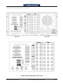
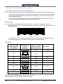
Connect the 25-pin D connector to the similar one on the rear of the Control Panel using the
cable provided.
•
Connect the 9-way D connector to the similar one on the rear of the Control Panel using the
cable provided.
•
If desired, a standard VGA monitor can be plugged into the 15-way sub-D connector at the
bottom rear of the panel. The signal frequency should be acceptable to the vast majority of
VGA-compatible monitors (see Specifications Section).
•
Finally, connect the 10 Base-T connector on the Control Panel to the socket on the Switcher
Mainframe marked “Panel 10 BASE TX” using the cable provided.
Connecting Panel to an “Alternate Mainframe”
The CP1512 Control Panel can be used to control another (Alternate) mainframe, e.g., a HD
system. The IP address of the alternate mainframe is set in the Miscellaneous - IP Address menu.
The alternate mainframe is connected to the primary mainframe via the 10 BASE T sockets.
Connect the 10 BASE T socket on the rear panel of the primary (Master) mainframe (adjacent to
the Panel 10 BASE TX connector) to the Panel 10 BASE TX socket on the alternate mainframe.
Power
Switch all power switches to their OFF states. Connect IEC power cables from the power socket(s)
on the rear of the Switcher Mainframe and Control Panel to the appropriate AC mains distribution
socket(s).
Page 6
SD1512 Installation Manual - Issue 8, Rev 1
S&W Production & Post Production