1
HCC334E
HCC484E
User Manual
HCMU000919 – Rev A – 02/04
ISSUE
DATE
A
February 2004
REVISIONS
Initial Release (PCN 1640)
ALL RIGHTS RESERVED. NO PART OF THIS PUBLICATION MAY BE
REPRODUCED BY ANY MEANS WITHOUT WRITTEN PERMISSION FROM
HONEYWELL VIDEO SYSTEMS. THE INFORMATION IN THIS PUBLICATION IS
BELIEVED TO BE ACCURATE IN ALL RESPECTS. HOWEVER, HONEYWELL
VIDEO SYSTEMS CANNOT ASSUME RESPONSIBILITY FOR ANY
CONSEQUENCES RESULTING FROM THE USE THEREOF. THE
INFORMATION CONTAINED HEREIN IS SUBJECT TO CHANGE WITHOUT
NOTICE. REVISIONS OR NEW EDITIONS TO THIS PUBLICATION MAY BE
ISSUED TO INCORPORATE SUCH CHANGES.
Rev. A
ii
HMMU000919
02/17/04
FCC COMPLIANCE STATEMENT
INFORMATION TO THE USER: THIS EQUIPMENT HAS BEEN
TESTED AND FOUND TO COMPLY WITH THE LIMITS FOR A
CLASS A DIGITAL DEVICE, PURSUANT TO PART 15 OF THE
FCC RULES. THESE LIMITS ARE DESIGNED TO PROVIDE
REASONABLE PROTECTION AGAINST HARMFUL
INTERFERENCE WHEN THE EQUIPMENT IS OPERATED IN A
COMMERCIAL ENVIRONMENT. THIS EQUIPMENT
GENERATES, USES, AND CAN RADIATE RADIO FREQUENCY
ENERGY AND, IF NOT INSTALLED AND USED IN
ACCORDANCE WITH THE INSTRUCTION MANUAL, MAY
CAUSE HARMFUL INTERFERENCE TO RADIO
COMMUNICATIONS. OPERATION OF THIS EQUIPMENT IN A
RESIDENTIAL AREA IS LIKELY TO CAUSE HARMFUL
INTERFERENCE IN WHICH CASE THE USER WILL BE
REQUIRED TO CORRECT THE INTERFERENCE AT HIS OWN
EXPENSE.
CAUTION: CHANGES OR MODIFICATIONS NOT EXPRESSLY
APPROVED BY THE PARTY RESPONSIBLE FOR COMPLIANCE
COULD VOID THE USER’S AUTHORITY TO OPERATE THE
EQUIPMENT.
THIS CLASS A DIGITAL APPARATUS COMPLIES WITH
CANADIAN ICES-003.
CET APPAREIL NUMÉRIQUE DE LA CLASSE A EST
CONFORME À LA NORME NMB-003 DU CANADA.
Rev. A
iii
HMMU000919
02/17/04
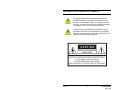
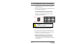
EXPLANATION OF GRAPHICAL SYMBOLS
The lightning flash with arrowhead symbol within an
equilateral triangle is intended to alert the user to the
presence of uninsulated "dangerous voltage" within the
product's enclosure that may be of sufficient magnitude
to constitute a risk of electric shock to persons.
The exclamation point within an equilateral triangle is
intended to alert the user to the presence of important
operating and maintenance (servicing) instruction in the
literature accompanying the product.
CAUTION
RISK OF ELECTRIC SHOCK
DO NOT OPEN
CAUTION: TO REDUCE THE RISK OF ELECTRIC SHOCK,
DO NOT REMOVE COVER (OR BACK).
NO USER-SERVICEABLE PARTS INSIDE.
REFER SERVICING TO QUALIFIED SERVICE PERSONNEL.
Rev. A
iv
HMMU000919
02/17/04
WARNINGS
Installation and servicing should be performed only by qualified
and experienced personnel.
Low voltage cameras must be powered from a UL listed class 2
power supply.
For outdoor use, an appropriate protective housing conforming
to IP65 or UL50 or better must be used.
Main camera is not evaluated by UL.
TO PREVENT FIRE OR SHOCK HAZARD, DO NOT
EXPOSE THIS CAMERA TO RAIN OR MOISTURE.
SAFEGUARDS
This camera range is designed for use in general-purpose CCTV
applications and no other purpose.
Only operate your camera between the temperature of -10ºC to
+50ºC (14ºF to 122ºF).
Do not operate your camera outside its specified power supply
range.
Camera must only be used in clean, dry, dust-free environments
unless housed in suitable protective housings to IP65 or better.
Rev. A
v
HMMU000919
02/17/04
ELECTROMAGNETIC COMPATIBILITY (EMC)
This is a class B product. In a domestic environment this
product may cause radio interference in which case the
user may be required to take adequate measures
INTENDED PURPOSE :
SECURITY AND SURVEILLANCE CCTV APPLICATIONS.
The product must be installed and maintained in accordance
with good installation practice to enable the product to function
as intended and to prevent problems. Refer to Honeywell Video
Systems for installation guidance
MANUFACTURER'S DECLARATION OF CONFORMANCE
The manufacturer declares that the equipment supplied with this
manual is compliant with the essential protection requirements
of the EMC directive 89/336 and the Low Voltage Directive LVD
73/23 EEC. Conforming to the requirements of standards EN
55022 for emissions, IEC801 parts 2, 3 and 4 for immunity and
EN 60065 for Electrical Equipment safety.
Rev. A
vi
HMMU000919
02/17/04
TABLE OF CONTENTS
SECTION 1: INTRODUCTION ............................................................... 1
1.1
INTRODUCTION ..........................................................................1
1.2
FEATURES ...................................................................................1
1.3
PACKAGE CONTENTS ................................................................2
SECTION 2: CAMERA SETTINGS......................................................... 3
2.1
CAMERA BACK ............................................................................3
2.2
AI/AES MODEL SELECTOR.........................................................3
2.3
AUTO IRIS LENS TYPE SELECTOR
(VIDEO DRIVE OR DIRECT DC DRIVE) .......................................3
2.4
AGC LOW / AGC HI .....................................................................4
2.5
BACKLIGHT COMPENSATION....................................................4
2.6
SYNCHRONIZATION SELECTION (LL/INT).................................4
2.7
LINE LOCK PHASE ADJUSTMENT POTENTIOMETER ..............5
2.8
DD LENS LEVEL ADJUSTMENT POTENTIOMETER...................5
2.9
POWER LED.................................................................................5
2.10 COMPOSITE VIDEO OUTPUT BNC CONNECTOR.....................6
2.11 POWER SUPPLY..........................................................................6
2.12 LENS SELECTION .......................................................................6
2.13 BACK FOCUS ADJUSTMENT......................................................6
SECTION 3: LENS INSTALLATION...................................................... 9
3.1
INSTALLING FIXED IRIS LENSES ...............................................9
3.2
INSTALLING MANUAL IRIS LENSES.........................................10
3.3
INSTALLING DIRECT (OR D.C.) DRIVE LENSES ......................11
3.4
INSTALLING VIDEO DRIVE LENSES .........................................12
3.5
CAMERA MOUNTING ................................................................13
Rev. A
vii
HMMU000919
02/17/04
TABLE OF CONTENTS, CONTINUED
SECTION 4: TROUBLESHOOTING..................................................... 15
4.1
NO POWER / LED NOT LIT........................................................15
4.2
NO VIDEO ..................................................................................15
4.3
POWER BUT PICTURE IS BLACK .............................................15
4.4
VIDEO IRIS .................................................................................16
4.5
DARK PICTURE..........................................................................16
4.6
PICTURE NOISE/GRAINY DURING DAYLIGHT OPERATION ...16
4.7
PICTURE TOO BRIGHT .............................................................16
4.8
PICTURE NOT SHARP (OUT OF FOCUS).................................17
4.9
PICTURE GOES SOFT (OUT OF FOCUS) IN LOW LIGHT........17
SECTION 5: SERVICE AND SUPPORT .............................................. 19
5.1
SERVICE AND SUPPORT ..........................................................19
5.2
LIMITED WARRANTY .................................................................20
SECTION 6: SPECIFICATIONS........................................................... 21
6.1
GENERAL SPECIFICATIONS.....................................................21
6.2
VIDEO SPECIFICATIONS ..........................................................22
Rev. A
viii
HMMU000919
02/17/04
SECTION 1:
INTRODUCTION
1.1
INTRODUCTION
Honeywell’s HCC484E and HCC334E color cameras are ideally
suited for use in day to day surveillance applications. Designed
for value, the HCC484E and HCC334E save time and money
with easy installation and reliable performance. Their off-theshelf feature set is designed for high picture quality in standard
applications and they require little to no adjustment once
installed.
1.2
Rev. A
FEATURES
•
1/3 Color CCD with Digital Signal Processing (DSP)
•
NTSC Scanning System
•
480 TV Lines Resolution (HCC484E)
330 TV Lines Resolution (HCC334E)
•
Low Light Performance
HCC484E: 0.55 lux (f1.2)
HCC334E: 0.66 lux (f1.2)
•
Automatic Backlight Compensation (BLC)
•
Automatic Electronic Shutter (AES)
•
12VDC / 24VAC with line lock
•
C/CS Lens Mount
•
Supports DD or Video Drive Auto Iris Lenses
•
Phase Adjustable Line Lock
1
HMMU000919
02/17/04
1.3
PACKAGE CONTENTS
1. Camera
2. Dust Cover
3. User Manual
Rev. A
2
HMMU000919
02/17/04
SECTION 2:
CAMERA SETTINGS
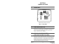
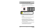
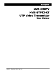
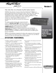
2.1
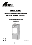
CAMERA BACK
* Default switch positions are shown.
Figure 1: Camera Back
2.2
AI/AES MODEL SELECTOR
The Electronic Iris (EI) feature compensates for excessive light
levels by automatically adjusting the shutter speed of the
camera. Select ON or OFF (default).
2.3
AUTO IRIS LENS TYPE SELECTOR
(VIDEO DRIVE OR DIRECT DC DRIVE)
Automatic iris lenses (direct drive (DC) or video drive types) are
connected to the camera via a 4-pin square socket located at
the right side of the camera. Use this switch on the rear of the
camera to select the type of automatic iris lens connected.
The default setting is DD (Direct or DC drive).
Rev. A
3
HMMU000919
02/17/04
2.4
AGC LOW / AGC HI
The Automatic Gain Control feature can improve picture quality
when the level of scene illumination is low. For most
applications, AGC HI should be selected.
2.5
BACKLIGHT COMPENSATION
If a strong background light such as a window exists in a scene,
the camera will try to compensate for it by reducing the overall
exposure. This would mean that areas surrounding the window
would become too dark. Backlight compensation (BLC) can be
set to ON to eliminate the effect of an area of strong background
lighting in a scene. The default setting is OFF.
BLC will only function with a manual iris lens when the
Electronic Iris feature is switched on. For direct drive and video
drive lenses, BLC will function even though the Electronic Iris
feature is switched off.
2.6
SYNCHRONIZATION SELECTION (LL/INT)
This switch is used to select the synchronization mode of the
camera. When the camera is connected to an AC supply, the
Line-lock (LL) mode can be used to lock the camera's frame rate
to the mains frequency so that each camera in the system is
triggered at the same point on the supply's AC-cycle.
(See also Line Lock Phase Adjustment Potentiometer.)
The default setting is INT.
Rev. A
4
HMMU000919
02/17/04
2.7
LINE LOCK PHASE ADJUSTMENT
POTENTIOMETER
When the camera is in line-lock mode it is possible to adjust the
point on the AC cycle at which the camera triggers. This facility
is provided so that cameras that are connected to different
mains phases may still be synchronized.
The line lock phase adjustment potentiometer allows the line
lock phase trigger point to be adjusted by :1:120°. Rotating the
potentiometer clockwise advances the trigger point and turning
it anticlockwise retards the trigger point. The factory default
setting is the zero crossing point. If all cameras in a system are
on the same mains phase then no line lock phase adjustment
should be made. (See also Synchronization Selection (LL/INT).)
2.8
DD LENS LEVEL ADJUSTMENT POTENTIOMETER
The Direct Drive lens level is controlled by this potentiometer.
The video output signal is converted into a DC voltage by
circuitry within the camera. The potentiometer sets a reference
voltage against which this derived DC voltage is compared. If
the DC voltage is less than the reference level, the lens iris
opening is increased. If the DC voltage is greater than the
reference level, the lens iris opening is decreased. This control
loop attempts to continually match the DC voltage derived from
the video signal, to the reference voltage set by the
potentiometer. This feature allows the installer to set the
required video output amplitude (e.g. 1Vpp) that the lens should
strive to maintain.
2.9
POWER LED
In normal operation, the LED on the rear panel of the camera is
illuminated when power is connected to the camera.
Rev. A
5
HMMU000919
02/17/04
2.10 COMPOSITE VIDEO OUTPUT BNC CONNECTOR
To obtain a 1.0Vpp composite video signal, connect a video
coaxial cable terminated with a 75 Ohm BNC connector to the
BNC socket marked VIDEO OUT.
2.11 POWER SUPPLY
The voltage required to operate the camera is clearly marked on
the rear panel of the camera. Connections are indicated above
the terminals on the rear panel of the camera. The power
supply must be a UL listed class 2 type.
2.12 LENS SELECTION
Suitable lens types are C- and CS-mount in fixed iris, manual iris,
video auto iris or direct drive auto iris versions. Cameras are
factory set for CS-mount lenses.
If using a C-mount lens, rotate the back focus adjustment
mechanism fully clockwise (when viewed from the front of the
camera) before fitting the lens-see Back Focus Adjustment.
2.13 BACK FOCUS ADJUSTMENT
The back focus adjustment is accessible at the front end of the
camera housing to adjust the back focal length or picture focus.
The range of adjustment allows both C- and CS- mount lenses
to be used without the need for a spacer ring.
Rev. A
6
HMMU000919
02/17/04
2.13 BACK FOCUS ADJUSTMENT, CONTINUED
To use the back focus mechanism:
1. Unlock the back focus mechanism using the Back Focus
adjustment lock (figure 1).
2. Rotate the back focus adjustment ring as required. When
viewed from the front of the camera, clockwise adjustment
moves the CCD sensor away from the back of the lens;
counter clockwise adjustment moves the CCD sensor
towards the back of the lens.
3. Lock the back focus mechanism
Rev. A
7
HMMU000919
02/17/04
NOTES:
Rev. A
8
HMMU000919
02/17/04
SECTION 3:
LENS INSTALLATION
3.1
INSTALLING FIXED IRIS LENSES
1. Turn the back focus adjustment ring fully clockwise (when
viewed from the front)-see Back Focus Adjustment.
2. Fit the lens to the camera.
3. If the lens has a focusing ring fitted, set it to infinity (∞) then
adjust the back focus.
4. Ensure the Electronic Iris (EI) and Automatic Gain Control
(AGC) features are both turned ON.
Rev. A
9
HMMU000919
02/17/04
3.2
INSTALLING MANUAL IRIS LENSES
1. Turn the back focus adjustment ring fully clockwise (when
viewed from the front).
2. Fit the lens to the camera and rotate clockwise until the lens
is fully screwed into the camera.
3. Turn the Electronic Iris (EI) and Automatic Gain Control
(AGC) features ON.
4. Adjust the back focus using the back focus ring on the front
of the camera. (See Section 2.13.)
Rev. A
10
HMMU000919
02/17/04
3.3
INSTALLING DIRECT (OR D.C.) DRIVE LENSES
1. Turn the back focus adjustment ring fully clockwise (when
viewed from the front.)
2. Fit the lens to the camera and rotate clockwise until the lens
is fully screwed into the camera.
If the lens is equipped with a 4-pin connector, plug the
connector into the terminal on the side of the camera.
If the lens is not equipped with the connector, connect it
according to the diagram below.
Pin #
DC Drive
Video Drive
Pin 1
Damp –
+12VDC
Pin 2
Damp +
NC
Pin 3
Drive +
Video
Pin 4
Drive –
GND
WARNING: The maximum load for this type of
lens must not exceed 25mA.
3. Set the Auto Iris selector (Figure 1, Switch 1) to AI.
4. Set the Auto Iris lens selector to DD for direct drive lenses.
5. Adjust the back focus using the back focus mounting ring
on the front of the camera. (See Section 2.13.)
6. With typical scene illumination, set the DD Lens Level
adjustment potentiometer (3, figure 1), lens iris for the
correct exposure. This can be achieved either visually,
or by using an oscilloscope to set the output of the camera
to 1 V peak-peak.
Rev. A
11
HMMU000919
02/17/04
3.4
INSTALLING VIDEO DRIVE LENSES
1. Turn the back focus adjustment ring fully clockwise (when
viewed from the front)-see Back Focus Adjustment.
2. Fit the lens to the camera and connect it according to the
diagram below.
Pin #
DC Drive
Video Drive
Pin 1
Damp –
+12VDC
Pin 2
Damp +
NC
Pin 3
Drive +
Video
Pin 4
Drive –
GND
WARNING: The maximum load for this type
of lens must not exceed 50mA.
3. Set the Auto Iris selector (Figure 1, Switch 1) to AI.
4. Set the Auto Iris lens selector switch to Video for video auto
iris lenses.
5. Adjust the back focus using the back focus mounting ring
on the front of the camera. (See Section 2.13.)
6. With typical scene illumination, set the Lens Level
adjustment potentiometer for the correct exposure. This can
be done visually. More accurate results will be achieved
using a video level meter or oscilloscope to set the output of
the camera to 1V peak-peak.
7. If the scene lighting conditions are extremely uneven, it may
be necessary to adjust the lens's Peak Average
potentiometer. Refer to the lens instructions.
Rev. A
12
HMMU000919
02/17/04
3.5
CAMERA MOUNTING
Mounting points are provided on the top and bottom of the
camera and are used to mount the camera on a bracket or
tripod. They are designed to accept standard photographic
mounting bolts (1/4" BSW or 20 UNC).
The mounting bracket must be capable of supporting the weight
of the camera and its lens. In cases where the lens is
substantially heavier than the camera, it is better to use the
mounting point on the lens itself.
NOTE: Some installation codes dictate that the mounting
bracket must be capable of supporting up to four times
the combined weight of the camera and lens.
The mounting bracket is not evaluated by UL.
Rev. A
13
HMMU000919
02/17/04
NOTES:
Rev. A
14
HMMU000919
02/17/04
SECTION 4:
TROUBLESHOOTING
4.1
NO POWER / LED NOT LIT
1. Check power connections.
2. Verify that the power supply is working.
(Use a camera that is known to be good.)
4.2
NO VIDEO
1. Check Power (see above).
2. Check BNC connections.
(Use a camera that is known to be good.)
3. Check Lens.
Remove lens, if video present, lens is source of problem.
4.3
POWER BUT PICTURE IS BLACK
1. DC Iris Check Auto iris lens selector switch is set to DC.
2. Increase DC level.
3. Check wiring connections.
4. Manual Iris: Check to make sure that iris is not closed.
Rev. A
15
HMMU000919
02/17/04
4.4
VIDEO IRIS
1. Verify that Auto iris lens selector switch is set to AI.
Increase level on lens.
2. Check wiring connections.
3. Try lens on another camera or known good lens on camera.
4.5
DARK PICTURE
1. Check lens iris.
2. Check coax termination is 75Ohm.
4.6
PICTURE NOISE/GRAINY DURING DAYLIGHT
OPERATION
Verify lens iris level with AGC function disabled.
4.7
Rev. A
PICTURE TOO BRIGHT
•
Manual IRIS: Switch electronic iris ON.
•
DC IRIS: Switch electronic iris OFF, reduce DC level.
•
Video IRIS: Switch electronic iris OFF, reduce level on lens.
16
HMMU000919
02/17/04
4.8
PICTURE NOT SHARP (OUT OF FOCUS)
1. Adjust focus on lens
2. Adjust back focus
4.9
PICTURE GOES SOFT (OUT OF FOCUS) IN LOW
LIGHT
Adjust focus under low light conditions or use a neutral density
filter under normal lighting conditions.
Rev. A
17
HMMU000919
02/17/04
NOTES:
Rev. A
18
HMMU000919
02/17/04
SECTION 5:
SERVICE AND SUPPORT
5.1
SERVICE AND SUPPORT
Refer servicing to qualified personnel or contact the Technical
Support at 1-800-796-CCTV for assistance.
Rev. A
19
HMMU000919
02/17/04
5.2
LIMITED WARRANTY
Honeywell International Inc. ("Seller"), 1305 Waters Ridge Drive, Lewisville, TX
75057, warrants this camera to be in conformance with its own plans and
specifications and to be free from defects in materials and workmanship under
normal use and service for a period of up to two (3) years from the date of
manufacture. Seller's obligation shall be limited to repairing or replacing, at its
option, free of charge for materials or labor, any product which is proved not in
compliance with Seller's specifications or proves defective in materials or
workmanship under normal use and service. Seller shall have no obligation under
this Limited Warranty or otherwise if the product is altered or improperly repaired
or serviced by anyone other than Honeywell factory service. For warranty service,
return product transportation prepaid, to Honeywell Video Systems Factory
Service, 1305 Waters Ridge Drive, Lewisville, TX 75077.
THERE ARE NO WARRANTIES, EXPRESS OR IMPLIED, OF MERCHANTABILITY,
OR FITNESS FOR A PARTICULAR PURPOSE OR OTHERWISE, WHICH EXTEND
BEYOND THE DESCRIPTION ON THE FACE HEREOF. IN NO CASE SHALL
SELLER BE LIABLE TO ANYONE FOR ANY CONSEQUENTIAL OR INCIDENTAL
DAMAGES FOR BREACH OF THIS OR ANY OTHER WARRANTY, EXPRESS OR
IMPLIED, OR UPON ANY OTHER BASIS OF LIABILITY WHATSOEVER, EVEN IF
THE LOSS OR DAMAGE IS CAUSED BY THE SELLER'S OWN NEGLIGENCE OR
FAULT.
Seller does not represent that the products it sells may not be compromised or
circumvented; that the products will prevent any personal injury or property loss by
burglary, robbery, fire or otherwise; or that the products will in all cases provide
adequate warning or protection. Customer understands that a properly installed
and maintained alarm may only reduce the risk of a burglary, robbery, fire or other
events occurring without providing an alarm, but it is not insurance or a guarantee
that such will not occur or that there will be no personal injury or property loss as a
result. CONSEQUENTLY, SELLER SHALL HAVE NO LIABILITY FOR ANY
PERSONAL INJURY, PROPERTY DAMAGE OR OTHER LOSS BASED ON A CLAIM
THE PRODUCT FAILED TO GIVE WARNING. HOWEVER, IF SELLER IS HELD
LIABLE, WHETHER DIRECTLY OR INDIRECTLY, FOR ANY LOSS OR DAMAGE
ARISING UNDER THIS LIMITED WARRANTY OR OTHERWISE, REGARDLESS OF
CAUSE OR ORIGIN, SELLER'S MAXIMUM LIABILITY SHALL NOT IN ANY CASE
EXCEED THE PURCHASE PRICE OF THE PRODUCT, WHICH SHALL BE THE
COMPLETE AND EXCLUSIVE REMEDY AGAINST SELLER. This warranty replaces
any previous warranties and is the only warranty made by Seller on this product.
No increase or alteration, written or verbal, of the obligations of this Limited
Warranty is authorized.
Rev. A
20
HMMU000919
02/17/04
SECTION 6:
SPECIFICATIONS
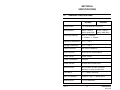
6.1
GENERAL SPECIFICATIONS
HCC484E
HCC334E
Image Sensor
1/3 Format Interline CCD Sensor
Pixel Elements
768 (H) × 494 (V)
approx. 380K pixels
Scanning Frequency
NTSC 2 : 1 Interlace /
H : 15750Hz , V : 59.94Hz
Operation Temperature
-10˚C ~ +50˚C
Storage Temperature
-20˚C ~ +60˚C
Output Terminals
BNC 75Ohm Unbalance
Input Terminals
3pin Push Lock Terminal Block
Power Source
12VDC / 24VAC
Power Consumption
4.2W Max,
Power Indicator
3ø Green LED on Rear Panel
IRIS Connector
4pin Connector on Side ( Panasonic
Standard ) for Video and DC Drive.
Lens Mount
CS ~ C Mount Adjustable
Back Focus Adjust
CS Mount 11mm ~ C Mount 18mm
Mounting Hole
1/4” Top and Bottom
Rev. A
21
510 (H) × 492 (V)
approx. 250K pixels
HMMU000919
02/17/04
6.2
VIDEO SPECIFICATIONS
Resolution
Minimum Illumination
Video Output
HCC484E
HCC334E
480 TV Lines
330 TV Lines
0.55Lux @ F=1.2
(50IRE Video
Output )
0.66Lux @ F=1.2
(50IRE Video
Output )
1.0Vpp 75Ohm BNC unbalance
S/N Ratio
50dB
AGC High Gain
36dB
AGC Low Gain
30dB
H Aperture
10 IRE ( r 0.45 100IRE Video Output )
V Aperture
10 IRE ( r 0.45 100IRE Video Output )
Gamma Compensation
0.45
Specifications are subject to change without prior notice for product
improvements. Actual specifications may vary depending on features
and components.
Rev. A
22
HMMU000919
02/17/04
Rev. A
23
HMMU000919
02/17/04
Video Systems
1305 Waters Ridge Drive
Lewisville, TX 75077
www.honeywellvideo.com
Unit 5, Riverside Centre
24-28 River Road West
Parramatta, NSW 2150
Australia
+61-2-8837-9300
www.ademco.com.au
53 Juta Street
Braamfontein
2001
South Africa
+ 27-11-403-3002
www.teqtrader.com
Aston Fields Rd.
Whitehouse Ind. Est
Runcorn
UK WA7 3DL
+ 44-1928-754000
www.videocontrols.co.uk
Via della Resistenza, 53/59
1 – 20090 Buccinasco
Milano
Italy
+39-02-4571791
www.ademcovideo.com
9315 NW 112th Avenue
Miami, FL 33178
USA
+1-305-805-8188
www.ademcoint.com
6554 176th Street
Surrey, BC V3S 4G5
Canada
+1-888-289-2288
www.silentwitness.com
Copyright © 2004 Honeywell International Inc.
Rev. A
24
HMMU000919
02/17/04