1
Draft
ETSI EN 300 338-2 V1.3.1 (2008-12)
European Standard (Telecommunications series)
Electromagnetic compatibility
and Radio spectrum Matters (ERM);
Technical characteristics and methods of measurement
for equipment for generation, transmission
and reception of Digital Selective Calling (DSC)
in the maritime MF, MF/HF and/or VHF mobile service;
Part 2: Class A/B DSC
2
Draft ETSI EN 300 338-2 V1.3.1 (2008-12)
Reference
REN/ERM-TG26-066-2
Keywords
maritime, radio, GMDSS, DSC
ETSI
650 Route des Lucioles
F-06921 Sophia Antipolis Cedex - FRANCE
Tel.: +33 4 92 94 42 00 Fax: +33 4 93 65 47 16
Siret N° 348 623 562 00017 - NAF 742 C
Association à but non lucratif enregistrée à la
Sous-Préfecture de Grasse (06) N° 7803/88
Important notice
Individual copies of the present document can be downloaded from:
http://www.etsi.org
The present document may be made available in more than one electronic version or in print. In any case of existing or
perceived difference in contents between such versions, the reference version is the Portable Document Format (PDF).
In case of dispute, the reference shall be the printing on ETSI printers of the PDF version kept on a specific network drive
within ETSI Secretariat.
Users of the present document should be aware that the document may be subject to revision or change of status.
Information on the current status of this and other ETSI documents is available at
http://portal.etsi.org/tb/status/status.asp
If you find errors in the present document, please send your comment to one of the following services:
http://portal.etsi.org/chaircor/ETSI_support.asp
Copyright Notification
No part may be reproduced except as authorized by written permission.
The copyright and the foregoing restriction extend to reproduction in all media.
© European Telecommunications Standards Institute 2008.
All rights reserved.
TM
TM
TM
TM
DECT , PLUGTESTS , UMTS , TIPHON , the TIPHON logo and the ETSI logo are Trade Marks of ETSI registered
for the benefit of its Members.
TM
3GPP is a Trade Mark of ETSI registered for the benefit of its Members and of the 3GPP Organizational Partners.
ETSI
3
Draft ETSI EN 300 338-2 V1.3.1 (2008-12)
Contents
Intellectual Property Rights ................................................................................................................................6
Foreword.............................................................................................................................................................6
1
Scope ........................................................................................................................................................7
2
References ................................................................................................................................................7
2.1
2.2
3
Normative references ......................................................................................................................................... 8
Informative references ........................................................................................................................................ 8
Definitions and abbreviations ...................................................................................................................8
3.1
3.2
4
Definitions .......................................................................................................................................................... 8
Abbreviations ................................................................................................................................................... 10
Controls and Indicators in Class A/B DSC Equipment ..........................................................................11
4.1
5
Visual indication .............................................................................................................................................. 11
Technical requirements ..........................................................................................................................11
5.1
5.1.1
5.1.2
5.2
5.3
5.4
6
Facilities for DSC transmission and reception ................................................................................................. 11
Multi-frequency distress alert attempts and watch receiver capabilities (MF/HF) ..................................... 11
Watch receiver capabilities (VHF) ............................................................................................................. 11
Remote alarms .................................................................................................................................................. 11
Galvanic isolation ............................................................................................................................................. 11
Manuals ............................................................................................................................................................ 11
Automated and Non-Automated Procedure Requirements in Class A/B DSC Equipment....................12
6.1
6.2
6.2.1
6.2.2
6.2.3
6.3
6.4
6.4.1
6.4.2
6.4.3
6.4.3.1
6.4.4
6.4.5
6.4.6
6.4.7
6.4.8
6.4.9
6.4.10
6.4.11
6.4.11.1
6.4.12
6.4.13
6.4.14
6.5
6.5.1
6.5.2
6.5.3
6.5.3.1
6.5.4
6.5.5
6.5.6
6.5.7
6.5.8
6.5.9
Introduction ...................................................................................................................................................... 12
Non-automated features ................................................................................................................................... 12
DSC Message Composition ........................................................................................................................ 12
Transmission of DSC messages and prioritized wait .................................................................................. 13
Alarms ........................................................................................................................................................ 14
Standby ............................................................................................................................................................. 14
Sending distress automated procedure ............................................................................................................. 15
Procedure .................................................................................................................................................... 15
Tasks ........................................................................................................................................................... 17
Display ........................................................................................................................................................ 17
Examples of sending distress procedure displays on VHF equipment .................................................. 18
Dedicated distress button sub procedure..................................................................................................... 19
Transmission of the alert attempt ................................................................................................................ 19
Updating position........................................................................................................................................ 20
Handling received DSC Messages .............................................................................................................. 20
Alarms ........................................................................................................................................................ 20
Determining Subsequent communications.................................................................................................. 20
Automated tuning ....................................................................................................................................... 20
Cancelling the Distress Alert ...................................................................................................................... 21
Examples of cancel-distress displays on VHF equipment..................................................................... 22
Acknowledgments ...................................................................................................................................... 22
Termination................................................................................................................................................. 22
Warnings ..................................................................................................................................................... 22
Receiving distress automated procedure .......................................................................................................... 23
Procedure .................................................................................................................................................... 23
Tasks ........................................................................................................................................................... 25
Display ........................................................................................................................................................ 25
Examples of received distress procedure displays on VHF equipment ................................................. 26
Handling received DSC Messages .............................................................................................................. 27
Alarms ........................................................................................................................................................ 27
Determining Subsequent communications.................................................................................................. 27
Automated tuning ....................................................................................................................................... 27
Acknowledgments ...................................................................................................................................... 27
Sending Relays and Acknowledgments ...................................................................................................... 28
ETSI
4
6.5.10
6.5.11
6.6
6.6.1
6.6.2
6.6.3
6.6.3.1
6.6.4
6.6.5
6.6.6
6.6.7
6.6.8
6.6.9
6.7
6.7.1
6.7.2
6.7.3
6.7.3.1
6.7.4
6.7.5
6.7.6
6.7.7
6.7.8
6.7.9
6.8
6.8.1
6.8.2
6.8.3
6.8.4
6.8.5
6.8.6
6.9
6.9.1
6.9.2
6.9.3
Draft ETSI EN 300 338-2 V1.3.1 (2008-12)
Termination................................................................................................................................................. 28
Warnings ..................................................................................................................................................... 28
Sending non distress automated procedure ...................................................................................................... 28
Procedure .................................................................................................................................................... 28
Tasks ........................................................................................................................................................... 29
Display ........................................................................................................................................................ 30
Examples of sending non distress procedures displays on VHF equipment ......................................... 31
Handling received DSC Messages .............................................................................................................. 31
Alarms ........................................................................................................................................................ 31
Automated tuning ....................................................................................................................................... 31
Delayed Acknowledgements ...................................................................................................................... 32
Termination................................................................................................................................................. 32
Warnings ..................................................................................................................................................... 32
Receiving non distress automated procedure ................................................................................................... 32
Procedure .................................................................................................................................................... 32
Tasks ........................................................................................................................................................... 33
Display ........................................................................................................................................................ 34
Examples of receiving non distress procedures displays on VHF equipment ....................................... 35
Handling received DSC messages .............................................................................................................. 35
Alarms ........................................................................................................................................................ 35
Automated tuning ....................................................................................................................................... 36
Acknowledgments ...................................................................................................................................... 36
Termination................................................................................................................................................. 36
Warnings ..................................................................................................................................................... 37
Communications automated procedure ............................................................................................................ 37
Procedure .................................................................................................................................................... 37
Tasks ........................................................................................................................................................... 37
Display ........................................................................................................................................................ 37
Handling received DSC Messages .............................................................................................................. 37
Tuning of the general receiver and transmitter ........................................................................................... 38
Termination................................................................................................................................................. 38
Multiple automated procedures and parallel event handling ............................................................................ 38
Procedure .................................................................................................................................................... 38
Tasks ........................................................................................................................................................... 38
Examples of multiple procedure screens .................................................................................................... 39
Annex A (normative):
DSC Message Composition ...........................................................................41
A.1
Default values .........................................................................................................................................41
A.2
The default DROBOSE ..........................................................................................................................42
A.3
Allowable non distress DSC message parameters..................................................................................42
Annex B (normative):
Radius-Centre point conversion and rounding algorithm .........................43
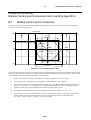
B.1
Radius-centre point conversion ..............................................................................................................43
B.2
Rounding ................................................................................................................................................44
B.3
Special cases for either form of area data entry .....................................................................................44
Annex C (normative):
Automated Non Distress Channel/Frequency Selection Algorithm ..........45
C.1
VHF ........................................................................................................................................................45
C.2
HF ...........................................................................................................................................................45
Annex D (normative):
Alarms .............................................................................................................46
D.1
Alarm specifications ...............................................................................................................................46
D.2
Alarming with critical errors ..................................................................................................................47
D.3
Default alarm sounds ..............................................................................................................................48
D.4
Other alarm sounds.................................................................................................................................48
ETSI
5
Annex E (informative):
Draft ETSI EN 300 338-2 V1.3.1 (2008-12)
Bibliography ...................................................................................................49
History ..............................................................................................................................................................50
ETSI
6
Draft ETSI EN 300 338-2 V1.3.1 (2008-12)
Intellectual Property Rights
IPRs essential or potentially essential to the present document may have been declared to ETSI. The information
pertaining to these essential IPRs, if any, is publicly available for ETSI members and non-members, and can be found
in ETSI SR 000 314: "Intellectual Property Rights (IPRs); Essential, or potentially Essential, IPRs notified to ETSI in
respect of ETSI standards", which is available from the ETSI Secretariat. Latest updates are available on the ETSI Web
server (http://webapp.etsi.org/IPR/home.asp).
Pursuant to the ETSI IPR Policy, no investigation, including IPR searches, has been carried out by ETSI. No guarantee
can be given as to the existence of other IPRs not referenced in ETSI SR 000 314 (or the updates on the ETSI Web
server) which are, or may be, or may become, essential to the present document.
Foreword
This European Standard (Telecommunications series) has been produced by ETSI Technical Committee
Electromagnetic compatibility and Radio spectrum Matters (ERM), and is now submitted f for the Public Enquiry phase
of the ETSI standards Two-step Approval Procedure.
The present document is part 2 of a multi-part deliverable. Full details of the entire series can be found in part 1 [i.2].
Proposed national transposition dates
Date of latest announcement of this EN (doa):
3 months after ETSI publication
Date of latest publication of new National Standard
or endorsement of this EN (dop/e):
6 months after doa
Date of withdrawal of any conflicting National Standard (dow):
6 months after doa
ETSI
7
1
Draft ETSI EN 300 338-2 V1.3.1 (2008-12)
Scope
The present document states the minimum requirements for equipment to be used for generation, transmission and
reception of Class A or B Digital Selective Calling (DSC) for use on board ships.
DSC may be used in the Medium Frequency (MF), High Frequency (HF) and Very High Frequency (VHF) Maritime
Mobile Service (MMS), for both distress, safety and general communications.
The present document is part 2 of a multi-part standard that covers the requirements to be fulfilled by equipment that is
either integrated with a transmitter and/or a receiver or equipment that is a stand-alone DSC terminal and has the
following class of DSC:
•
Class A - includes all the facilities defined in annex 1 of ITU-R Recommendation M.493-12 [3] and complies
with the IMO Global Maritime Distress and Safety System (GMDSS) carriage requirements for MF/HF
installations and/or VHF installations;
•
Class B - provides minimum facilities for equipment on ships not required to use class A equipment and
complies with the minimum IMO GMDSS carriage requirements for MF and/or VHF installations. This
equipment should provide for:
-
alerting, acknowledgement and relay facilities for distress purposes;
-
calling and acknowledgement for general communication purposes; and
-
calling in connection with semi-automatic/automatic services, as defined in
ITU-R Recommendation M.493-12 [3], annex 2, clause 3.
These requirements include the relevant provisions of the ITU Radio Regulations [2] and ITU-R Recommendations, the
International Convention for the Safety Of Life At Sea (SOLAS) [1], and the relevant resolutions of the International
Maritime Organization (IMO).
2
References
References are either specific (identified by date of publication and/or edition number or version number) or
non-specific.
•
For a specific reference, subsequent revisions do not apply.
•
Non-specific reference may be made only to a complete document or a part thereof and only in the following
cases:
-
if it is accepted that it will be possible to use all future changes of the referenced document for the
purposes of the referring document;
-
for informative references.
Referenced documents which are not found to be publicly available in the expected location might be found at
http://docbox.etsi.org/Reference.
For online referenced documents, information sufficient to identify and locate the source shall be provided. Preferably,
the primary source of the referenced document should be cited, in order to ensure traceability. Furthermore, the
reference should, as far as possible, remain valid for the expected life of the document. The reference shall include the
method of access to the referenced document and the full network address, with the same punctuation and use of upper
case and lower case letters.
NOTE:
While any hyperlinks included in this clause were valid at the time of publication ETSI cannot guarantee
their long term validity.
ETSI
8
2.1
Draft ETSI EN 300 338-2 V1.3.1 (2008-12)
Normative references
The following referenced documents are indispensable for the application of the present document. For dated
references, only the edition cited applies. For non-specific references, the latest edition of the referenced document
(including any amendments) applies.
[1]
International Convention for the Safety of Life at Sea (1974) as amended.
[2]
ITU Radio Regulations (2008).
[3]
ITU-R Recommendation M.493-12: "Digital selective-calling system for use in the maritime
mobile service".
2.2
Informative references
The following referenced documents are not essential to the use of the present document but they assist the user with
regard to a particular subject area. For non-specific references, the latest version of the referenced document (including
any amendments) applies.
[i.1]
IMO Regulation IV/14, regulation X/3, IV/6.6, IMO resolution MSC.97 (73) 14.6.4.
[i.2]
ETSI EN 300 338-1: "Electromagnetic compatibility and Radio spectrum Matters (ERM);
Technical characteristics and methods of measurement for equipment for generation, transmission
and reception of Digital Selective Calling (DSC) in the maritime MF, MF/HF and/or VHF mobile
service; Part 1: Common requirements".
3
Definitions and abbreviations
3.1
Definitions
For the purposes of the present document, the following terms and definitions apply:
acknowledged: automated procedure it indicates that the objective of the initial DSC message has been achieved
active: automated procedure which has control of the general receiver and transmitter and is thus able to engage in
subsequent communications and receive DSC messages on both the watch receiver and general receiver
automated procedure: set of actions necessary to complete the objective of an initiating DSC message or non DSC
communication event
NOTE 1: Four DSC automated procedures are designed to process these. They are the receiving of distress DSC
messages, the receiving of non distress DSC messages, the sending of distress DSC alert attempts and the
sending of non distress DSC messages. In addition a fifth procedure is designed to handle non DSC
communication events.
NOTE 2: These automated procedures are called:
Received distress automated procedure.
Sending distress automated procedure.
Received non-distress automated procedure.
Sending non-distress automated procedure.
Communications automated procedure.
ETSI
9
Draft ETSI EN 300 338-2 V1.3.1 (2008-12)
critical errors: set of information characters obtained from one or more received DSC messages is considered to have
critical errors if the automated procedure needs information characters from that set in order to proceed or perform any
task, but the required information characters are in error
EXAMPLE:
An acknowledgement cannot be composed to an individual DSC message that has errors in the
senders MMSI).
default: value selected or an action taken by the equipment software in the absence of any operator input
distress alert: name given to the single distress DSC message with the format symbol 112
distress alert attempt: set of distress alerts sent by a vessel when in distress
NOTE:
A distress alert DSC message by itself is never intentionally sent by a vessel in distress. For example, the
single frequency distress alert attempt consists of five consecutive distress alerts with no break in between
each distress alert.
distress DSC message: DSC message or acknowledgement containing the distress information
distress event: unique distress situation identified by two (VHF) or three (MF/HF) parameters of the distress
information; the MMSI of the vessel in distress and the nature of distress and on MF/HF the mode of subsequent
communication
distress information: symbols within a DSC message describing a distress situation consisting of the MMSI of the
vessel in distress, the nature of distress, the position of the vessel in distress, the UTC time of that position, and the
mode of subsequent communication
engaged: used to indicate that the equipment is busy handling an automated procedure
factory default: default value that is set by the manufacturer such that the field or behaviour is defined prior to any
operator intervention
general receiver: receiver part of the transceiver used for the reception of all subsequent communications and on HF
the reception of DSC acknowledgements on the duplex DSC channels
NOTE:
It is important to distinguish this unit from the watch receiver.
Information characters: set of symbols in a DSC message that contains the items of interest for the recipient and is
used to compute the ECC symbol that terminates the message
NOTE:
These symbols are repeated in the DX/RX time diversity pattern.
initial DSC message: DSC message that starts an automated procedure
non distress DSC message: DSC messages or acknowledgments that do not have the format specifier or category of
"distress"
objective: when in reference to a DSC message or automated procedure, the goal or intent of the item
NOTE:
Usually this goal or intent is to establish subsequent communications or request information.
on hold: automated procedure which does not have access to the transmitter and general receiver and therefore cannot
engage in subsequent communications and is only able to receive DSC messages on the watch receiver
operator options: any choices the operator can make while the automated procedure is engaged
parallel event handling: background process of handling a received DSC message that is not pertinent to the active
automated procedure
pertinent to the automated procedure: expression used primarily with reference to DSC messages to indicate that the
message has something to do with the procedure and is therefore "handled" by the procedure
NOTE:
A DSC message is pertinent to an automated procedure if the set of information characters in the DSC
message has the correct values.
pertinent to the station: any DSC message that would start an automated procedure if the transceiver were in standby
ETSI
10
Draft ETSI EN 300 338-2 V1.3.1 (2008-12)
self-terminating alarm: short alarm that stops by itself without operator intervention
NOTE:
The purpose of this alarm is to inform the operator that a DSC message is received but it does not require
his immediate attention.
standby: the equipment is not handling an automated procedure, either active or on hold, but is able to receive DSC
messages
symbol (as part of the DSC sentence): the term "symbol" used to describe the 7 binary bits of a 10 bit DSC word that
have the information content
toggle (between automated procedures): ability to make one automated procedure active assuring that all other
procedures go on hold
top level: top level means that items, buttons, or functions are present and visible without requiring any action by the
operator (such as scrolling, opening up menus, or removing any obscuring covers, etc.)
two-tone alarm: alarm consisting of a repetition of the 2 200 Hz frequency for 250 ms followed by a 1 300 Hz
frequency for 250 ms
NOTE:
This alarm is used for the initiation of the received distress DSC automated procedure. The characteristics
of this alarm on the equipment shall not be able to be altered.
urgency alarm: alarm consisting of a repetition of the 2 200 Hz frequency for 250 ms followed by 250 ms period of
silence
NOTE:
This alarm is used for the initiation of the received non distress DSC automated procedure when the
category of the initiating DSC message is "urgency". The characteristics of this alarm on the equipment
shall not be able to be altered.
watch receiver: this unit is the separate receiver in DSC radios that continuously monitors the DSC distress frequencies
on MF/HF, 2 187,5 kHz on MF, and channel 70 on VHF
NOTE:
On MF/HF it is sometimes referred to as the scanning receiver.
word (as part of the DSC sentence): term "word" used to describe the 10 binary bits that make up the coded entities of
a transmitted DSC message
NOTE:
3.2
The 10 bits consist of a 7 bit "symbol" that gives the information content and 3 bit error check that gives
the number of 0 binary bits in the 7 bit symbol.
Abbreviations
For the purposes of the present document, the following abbreviations apply:
AIS
ALE
DROBOSE
DSC
ECC
EUT
GMDSS
HF
IEC
ISO
ITU
ITU-R
ITU-T
MF
MMSI
NBDP
UTC
VHF
universal shipborne Automatic Identification System
Automatic Linking Exchange
Distress Relay On Behalf Of Someone Else
Digital Selective Calling
Error Check Character
Equipment Under Test
Global Maritime Distress and Safety System
High Frequency
International Electrotechnical Commission
International Standardization Organization
International Telecommunications Union
ITU - Radiocommunications Sector
ITU - Telecommunications Sector
Medium Frequency
Maritime Mobile Service Identity
Narrow Band Direct Printing
Universal Time Co-ordinated
Very High Frequency
ETSI
11
Draft ETSI EN 300 338-2 V1.3.1 (2008-12)
4
Controls and Indicators in Class A/B DSC Equipment
4.1
Visual indication
Any visual display of the information content shall be clearly legible under all ambient light conditions.
The display shall be large enough to hold enough information from the active procedure to safely guide the operator
through operator options in any engaged DSC procedure (distress or non-distress). It shall at any time hold information
on how to instantly recall any waiting procedure, or put any active procedure on hold.
The amount of information to display simultaneously on the display shall correspond to the information that can be
written in plain text with a minimum of 160 characters, each character having a minimum height of 3,5 mm, and a
nominal character width/height ratio of 0,7.
Where logic flows and procedural guidance, expressed by graphical symbols, have an advantage over text, this shall be
allowed. Any graphical symbols shall be clearly defined in the operation manual.
All DSC displays at all operating positions shall comply with these requirements.
5
Technical requirements
5.1
Facilities for DSC transmission and reception
5.1.1
Multi-frequency distress alert attempts and watch receiver
capabilities (MF/HF)
The equipment shall either:
•
be capable of receiving DSC messages on all distress frequencies (except for the transmit frequency in use)
whilst the distress alert is being transmitted; or
•
be able to complete the multi-frequency distress alert attempt within one minute.
5.1.2
Watch receiver capabilities (VHF)
The watchkeeping receiver part of the DSC equipment shall be designed for continuous operation on channel 70 but the
receiver need not operate when the transmitter is in use on that channel.
5.2
Remote alarms
The equipment shall be provided with facilities for connecting remote alarms as recommended in IMO Regulation
IV/14, regulation X/3, IV/6.6, IMO resolution MSC.97 (73) 14.6.4 [i.1].
5.3
Galvanic isolation
No exposed metallic part of the equipment shall cause any terminal of the source of electrical energy to be earthed.
5.4
Manuals
Maintenance or service manuals shall be available and shall contain:
•
If the equipment is so constructed that fault diagnosis and repair is practicable down to component level, the
maintenance instructions shall include full circuit diagrams, component layouts and components parts lists.
ETSI
12
•
Draft ETSI EN 300 338-2 V1.3.1 (2008-12)
If the equipment contains modules in which fault diagnosis and repair down to component level is not
practicable, the maintenance instructions shall contain sufficient information to enable localization and
replacement of the defective module.
6
Automated and Non-Automated Procedure
Requirements in Class A/B DSC Equipment
6.1
Introduction
This clause covers the minimum level of software automation, operational simplicity, and interface consistency
requirements for shipborne fixed installations using class A/B Digital Selective Calling equipment as specified in
ITU-R Recommendation M.493-12 [3] annexes 1, 3 and 4.
Perhaps the most important issue concerns an implied expectation for the use of the terminology "automated procedure"
as used in the present document to appear in the user interface. The terminology "automated procedure" describes the
set of algorithms that are used to encapsulate all the activities necessary to perform multitasking, DSC, and non DSC
communication events. The operator does not need to know anything about the existence of automated procedures in
order to operate a radio that makes use of these algorithms. Though the present document refers to items such as the
"Sending Distress Automated Procedure" such language shall not appear on the user interface of the equipment.
The primary purpose of DSC signalling is to provide the means to set-up subsequent communications between vessels
and/or coast stations. A call may be considered as being the total duration from the start of the DSC signalling until the
end of the subsequent communications, and the automated procedure is terminated.
The operational functionality described in this part has the objective of not disturbing any ongoing call. Furthermore,
the equipment shall assist the operator by providing simple audible indication of a received DSC call whilst the
equipment is engaged, and provide a facility to manage activation amongst initiated automated procedures.
6.2
Non-automated features
This clause describes the features of the equipment that are necessary to assure compliance to the ITU-R DSC
functionality standards and support a smoother operation of the automation algorithms, but are not directly related to the
automation algorithms.
6.2.1
DSC Message Composition
The equipment shall provide factory default values for all non distress DSC messages as specified in ITU-R
Recommendation M.493-12 [3] annex 3 and summarized in figure A.1 for all parameters where the operator has the
option to select or enter more than one value and has not already done so.
The default values for the Distress Relay On Behalf Of Someone Else (DROBOSE) shall be as given in table A.1.
The default values for the operator-composed distress alert shall be the default distress alert as specified in the sent
distress automated procedure.
A destination MMSI that does not have at least 9 digits entered is invalid.
The MMSI "unknown" indicator shall only be able to be used for the MMSI of the vessel in distress when composing a
DROBOSE.
No DSC message shall be able to be sent that has an invalid parameter.
For simplicity of the user interface:
a)
the DSC message composition interface shall be such that the operator needs no user manual to initiate the
desired DSC message;
b)
it shall require a maximum of two keystrokes, button pushes or menu actions plus the entry or selection of a
destination MMSI for the operator to send the default (routine individual) DSC message from standby;
ETSI
13
Draft ETSI EN 300 338-2 V1.3.1 (2008-12)
c)
parameter descriptions and terms shall be provided in plain language;
d)
all parameters of the DSC message that do not require an operator choice shall be entered automatically;
e)
guidance and/or prompting shall be provided for the entry of any necessary parameters of the DSC message if
these parameters and/or their values are not plainly visible from context or on the display.
For data entry:
a)
the equipment shall only allow the operator to compose and send DSC messages that are compliant with the
latest version of ITU-R recommendation M.493-12 [3];
b)
acknowledgements shall be automatically composed by the equipment and user options for these
acknowledgements are provided by the automated procedures;
c)
the equipment shall provide the operator with the choice of specifying the geographic area parameters as either
a circle of radius "r" about a centre point or the traditional latitude-longitude Mercator box and northwest
corner point or about a centre point;
d)
the equipment shall convert and round the radius-centre point entry according to the algorithm given in
annex B;
e)
the equipment shall provide an automatic determination of the channel and or frequencies of subsequent
communication according to the algorithm given in ITU-R Recommendation M.493-12 [3] annex 3 and
summarized in annex C.
The automated channel selection shall be able to be overridden.
It shall not be possible to select a distress channel for subsequent communications for DSC messages of priority routine.
The equipment shall automatically set the dot pattern length to 20 bits for all transmitted DSC messages on VHF, and
on MF/HF all DSC messages addressed to a coast station and all individual acknowledgements with format specifiers
120 and 123.
Furthermore MF/HF equipment shall automatically set the dot pattern length to 200 bits for all transmitted DSC
messages for:
•
distress alerts;
•
distress acknowledgements;
•
distress relays addressed to a geographic area;
•
distress relay acknowledgements addressed to all ships;
•
all calls addressed to a ship station other than messages addressed to a coast station or all individual
acknowledgements with format specifiers 120 and 123.
6.2.2
Transmission of DSC messages and prioritized wait
If the channel is free after the transmitter has powered up, the transmission shall begin immediately. If the channel is
not free, and the DSC message is a distress alert, the alert shall be transmitted as soon as the channel becomes free or
after 10 s on MF or HF or 1 s on VHF, which ever occurs first. (The 10 s and 1 s values are approximate average times
for HF and VHF DSC messages, respectively.) For all other DSC messages, the equipment shall wait for the channel to
become free and then the equipment shall delay transmission of the DSC message for a specified wait time.
The specified wait time shall depend upon the message type and priority. Distress DSC messages (except for alerts),
urgency, safety, routine and test DSC messages shall wait one, two, three, and four "fixed" units of time plus a random
addition described below, respectively, before attempting to transmit. Transmission occurs if and only if the channel is
still free after this wait time has elapsed, otherwise the process is repeated.
The fixed "unit" of time shall be 100 ms on MF and HF and 50 ms on VHF. The randomly generated component shall
be some positive integer with resolution in milliseconds between zero and the fixed interval. The random component
serves as a tie breaker when multiple DSC messages of the same priority and type are waiting to be transmitted. The
randomly generated part of the wait time shall be recomputed for every transmission attempt.
ETSI
14
Draft ETSI EN 300 338-2 V1.3.1 (2008-12)
For example, on HF, the random interval would be some positive integer of milliseconds between 0 ms and 100 ms, for
example, 56 ms. Thus the wait time for a routine DSC message in this example would be 456 ms the first attempt. If the
channel was once again busy after the wait time expired, the new wait time might be 417 ms the second attempt, etc.
6.2.3
Alarms
Alarms shall have both a visual and aural component.
Any alarm that initiates for the purpose of getting the operator's attention shall provide the reason for and means to
terminate the alarm.
Alarms shall be initiated for the reasons given in table D.1.
The means to terminate the alarms are given in table D.1.
The "two-tone" and "urgency-sound" alarms shall not be able to be disabled.
The default aural alarms are given by table D.2.
Some alarm tones may be customized by the operator as shown in table D.2.
6.3
Standby
NOTE:
Standby is the state of the equipment when it is not engaged in a communications or DSC automated
procedure. The state of the equipment is considered engaged whether the automated procedure is active or
on hold.
The following functions and or information shall be visible to the operator at top level while in standby:
a)
the station MMSI;
b)
the latest position of the vessel;
c)
the UTC time of that position;
d)
the dedicated distress button;
e)
a clearly labelled means to compose a distress alert prior to sending distinct from the dedicated distress button;
f)
a clearly labelled means to compose/send a non distress DSC message;
g)
a clearly labelled means to compose/send a DROBOSE.
The following setup options shall be available with the following factory defaults:
a)
the option to send medical transport DSC messages: set to off;
b)
the option to send neutral crafts DSC messages: set to off;
c)
the option to auto acknowledge polling DSC messages: set to on;
d)
the option to auto acknowledge test DSC messages: set to on;
e)
the option to auto acknowledge position request DSC messages: set to off;
f)
the option to auto acknowledge individually addressed, non distress DSC messages: set to on
(see clause 6.7.7);
g)
the option on MF/HF equipment to set the maximum distance for sounding a two-tone alarm that does not self
terminate upon initiation of a received distress automated procedure to some value greater than or equal to 500
nautical miles that includes "never self terminate": set to 500 nautical miles;
h)
the option to set the no activity timeout to exit any non automated procedure activity to some value that
includes no timeout: set to 10 min;
ETSI
15
Draft ETSI EN 300 338-2 V1.3.1 (2008-12)
i)
the option to set the no activity timeout of non distress DSC automated procedures to some value that includes
no timeout: set to 15 min;
j)
the option to set the no activity timeout of received distress DSC automated procedures to some value that
includes no timeout: set to no timeout;
k)
that there is no option to set any timeout of the unacknowledged sending distress automated procedure;
l)
the option to set the maximum amount of simultaneous automated procedure (applies only to equipment that
supports more than the required minimum of seven);
m)
the option to set the no activity timeout of communications automated procedures to some value in the range
[10 s to 10 min]: set 30 s.
A record of the DSC activity shall be available containing the following information which shall be able to be
displayed:
a)
the UTC time and date of reception;
b)
on MF/HF the frequency of reception;
c)
the information content of the DSC message;
d)
a minimum of the twenty most recently received distress DSC messages; a single or multi frequency alert
attempt shall be recorded as a single DSC message with an indication of how many of the alerts in the attempt
were received. DSC alerts received on the same frequency within a period of 60 s (MF/HF) and 5 s (VHF)
shall be considered part of the same distress alert attempt. On MF/HF consecutive alerts received on different
frequencies within a period of 60 s shall be considered a multi frequency attempt. In both cases, the
information characters assimilated by the automated procedure handling the distress alerts shall be the
recorded information characters. In other words, if any errors in the information characters of a received alert
are corrected by the reception of other alerts within the attempt, only the corrected version shall be recorded;
e)
a minimum of the twenty most recently sent DSC messages, where a distress alert attempt is recorded as a
single message;
f)
a minimum of the twenty most recently received non distress DSC messages.
6.4
Sending distress automated procedure
6.4.1
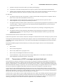
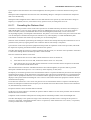
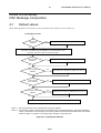
Procedure
The sending distress automated procedure results when the operator presses the dedicated distress button to send a
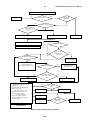
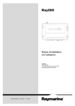
distress alert attempt. An informative schematic of the outline of the automated procedure is given in figure 1.
ETSI
16
Draft ETSI EN 300 338-2 V1.3.1 (2008-12)
PUSH DISTRESS BUTTON
Distress Button Sub Procedure
No
End
procedure
Completed?
Yes
Transmission Sub Procedure
with updated position and time of position,
and default or optional entered distress
information
Compute time to next attempt; Tune radio to comms freq
Options:
- Pause countdown
- Resend attempt
- Change attempt (HF)
- Pick comms freq (HF)
- Cancel Procedure
Ack received
and attempt
stopped
Enter "acked" stage and
sound ack alarm.
Yes
ack?
No
Yes
Received DSC?
log DSC
No
Tune radio
Received
DSC?
No
Time to next
attempt?
No
Yes
Yes
Repeat ack
from same
station?
No
Inform/
allocate (multistation
relays may
be ignored)
Options:
- End procedure
- Pick comms
- hold/activate
Yes
Short alarm
Figure 1: Sending distress procedure
ETSI
End
procedure
17
6.4.2
Draft ETSI EN 300 338-2 V1.3.1 (2008-12)
Tasks
The radio shall follow the sending distress automated procedure as shown in figure 1 complying with the automated
procedures as defined in ITU-R Recommendation M.493-12 [3], annex 4.
The sending distress automated procedure shall handle the following events:
a)
the distress button sub procedure;
b)
previous to the procedure being acknowledged:
c)
6.4.3
1)
on HF the setting of the watch receiver to scan all six distress frequencies (if not already doing so);
2)
the transmission of the alert attempt;
3)
calculating the time to an automated resending of the attempt (random, between 3,5 min and 4,5 min);
4)
tuning to the subsequent communication frequency (upon conclusion of the attempt);
5)
waiting for the reception of a distress alert acknowledgement;
6)
logging all other received DSC messages assuring they do not disrupt the procedure;
7)
retransmission of the alert attempt occurs after the calculated resend timer expires (3);
8)
providing the valid operator options which are:
i)
pausing the countdown to automated resending;
ii)
resending the alert attempt, with the last entered other parameters, using the dedicated DISTRESS
button;
iii)
cancelling the alert attempt;
iv)
selecting amongst the six frequencies of subsequent communications (HF only);
after reception of the acknowledgement:
1)
stopping the automatic resending of the alert attempt;
2)
transmitting any remaining single alert of the attempt to completion;
3)
allocating received DSC messages not pertinent to the procedure to their appropriate automated
procedures or initiating its own procedure on hold; and
4)
providing the valid operator options which are:
i)
selecting amongst the six frequencies of subsequent communications (HF only);
ii)
activate or place the procedure on hold; and
iii)
terminating the automated procedure.
Display
During the sending distress automated procedure the radio shall display the following items and/or information as
appropriate at top level:
1)
the fact one is engaged in sending a distress;
2)
the time remaining to the next automated resending of the attempt (prior to acknowledgement);
3)
the elapsed time since receiving the distress alert acknowledgement (after acknowledgment);
4)
indicate whether the procedure is on hold or is active (after acknowledgement);
5)
the distress information;
ETSI
18
Draft ETSI EN 300 338-2 V1.3.1 (2008-12)
6)
a warning before the automated resending of the attempt in case engaged in traffic;
7)
the frequency of subsequent communication (HF only);
8)
the frequencies on which the alerts are sent (HF only);
9)
the MMSI of the sender of the distress acknowledgement;
10) the sub-stages of the procedure:
a)
transmitting;
b)
waiting for acknowledgement;
c)
alert acknowledged;
d)
waiting for a free channel; and
11) the valid operator options.
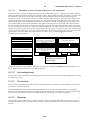
6.4.3.1
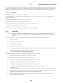
Examples of sending distress procedure displays on VHF equipment
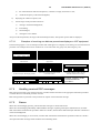
In the following set of figures examples are shown of windows that could appear on a display screen during a sending
distress automated procedure at various stages during the event. The first figure is what might appear after the operator
holds down the dedicated distress button for 3 or more seconds. The second figure shows the window after the alert
attempt has completed. The procedure is waiting for a distress alert acknowledgement and the radio is tuned for distress
traffic on channel 16. The operator has several options; to cancel the alert, resend the alert before the auto-resend
timeout, pause the countdown to the auto-resending, and to look at detailed information about the sent alert. The "info"
must contain, at minimum, the distress information. Note there is no option to "abort" the alert; the operator must go
through the cancel procedure. The third figure is four minutes later. There may have been voice traffic but no authority
has acknowledged the alert. The next figure is two seconds later and now the EUT is warning the operator that the
distress alert will be automatically resent in 9 seconds. The operator could press the pause button to stop the countdown
(perhaps there is voice traffic) at which time the button would say "resume" or something like that. The fifth figure
shows the retransmission of the alert and the sixth figure a short time later after the transmission has finished. Note the
different time to the auto resend in the fifth figure. In the seventh figure the distress alert acknowledgement has been
received. An alarm would sound that needs manual termination, and the text bar indicating the alarm information would
likely flash or provide some other visual alarm signal. The eighth figure shows the acknowledged procedure. Note the
operator options have changed and the procedure is still tuned for distress traffic. At this point, the DSC phase has
accomplished its purpose and linked the vessel in distress to assistance/authorities. Until the procedure is terminated,
the procedure remains.
!! DISTRESS !! Undesignated
!! DISTRESS !! Undesignated
Transmitting alert
Waiting for reply: 2:09
Waiting for reply: 6:09
Time to auto-resend: 4:22
Time to auto-resend: 4:11
Time to auto-resend: 0:11
Cancel
Undesign
Resend
Pause
Undesign
Info
Cancel
Undesign
Resend
Pause
Undesign
Info
!! DISTRESS !! Undesignated
Cancel
Undesign
Resend
Pause
Undesign
!! DISTRESS !! Undesignated
!! DISTRESS !! Undesignated
!! 9 seconds to auto-resend !!
Transmitting alert
Waiting for reply: 6:54
Time to auto-resend: 0:09
Time to auto-resend: 3:39
Time to auto-resend: 3:05
Cancel
Undesign
Resend
Pause
Undesign
Info
Cancel
Undesign
Resend
Pause
Undesign
Info
Our DISTRESS acknowledged
Our DISTRESS acknowledged
Reply received!!
Since 0:14
Quit
Undesi
Info
hold
Silence
Quit
Undesi
Info
Info
!! DISTRESS !! Undesignated
Cancel
Undesign
Resend
Pause
Undesign
Info
Example "windows" of the
sending distress automated
procedure at various stages.
hold
The above examples are only examples. They show one means of providing the minimum required information. The
layout, method, and choice of text are up to the manufacturer.
ETSI
19
6.4.4
Draft ETSI EN 300 338-2 V1.3.1 (2008-12)
Dedicated distress button sub procedure
The dedicated distress button shall be used for the following purposes in the following manner:
a)
use of the dedicated distress button is required to initiate the sending distress automated procedure;
b)
the dedicated distress button shall be used exclusively for initiating the sending distress automated procedure;
c)
use of the dedicated distress button after entering parameters of the alert attempt via a menu or equivalent shall
initiate the sending distress automated procedure with the alert attempt as composed by the operator;
d)
use of the dedicated distress button without entering parameters of the alert attempt via a menu or equivalent
shall initiate the sending distress automated procedure with the default alert attempt. The default alert attempt
is given by the following:
1)
undesignated nature of distress;
2)
the latest position of the vessel;
3)
the UTC time of that position;
4)
radio telephone for subsequent communication;
5)
on HF the multi frequency attempt using all six frequencies.
Use of the dedicated distress button without entering parameters of the alert attempt via a menu or equivalent shall
initiate the sending distress automated procedure with the default alert attempt regardless of the state of the radio,
except when the radio is already engaged in the sending distress automated procedure.
The distress button sub procedure of the sending distress automated procedure shall be as follows:
a)
lifting of the spring loaded lid or cover permanently attached to the equipment by, for example, hinges. This is
ACTION 1;
b)
pressing and holding the distress button (ACTION 2) while:
i)
displaying the seconds remaining to transmission of the attempt starting at three; and
ii)
invoking an intermittent audio and intermittent visual alarm once each second;
c)
stopping the procedure if the distress button is released before the three seconds have elapsed (when releasing
the button the radio shall return to its previous state);
d)
when the three seconds have elapsed regardless of whether the button is continued to be held down or released
completes ACTION 2 and the alert attempt is started;
e)
sounding a steady tone of two-second duration after ACTION 2 has completed and displaying a visual
indication that the distress alert attempt has been sent.
6.4.5
Transmission of the alert attempt
The transmission sub procedure of the sending distress automated procedure shall be as follows:
a)
the appropriate frequencies for transmission shall be determined from the selected frequencies;
b)
on VHF it is always channel 70 and thus always a single frequency attempt;
c)
on MF it is always 2 187,5 kHz and thus always a single frequency attempt;
d)
for an HF single frequency attempt a frequency is chosen from a list of six possible frequencies (default all
six) previously set up by the operator during equipment installation. Each time the attempt is automatically (or
manually) repeated the next frequency in the list is used until all frequencies are utilized at which time the
cycle repeats;
ETSI
20
Draft ETSI EN 300 338-2 V1.3.1 (2008-12)
e)
for an HF multi frequency attempt a list of three to six frequencies (2 MHz and 8 MHz mandatory, default all
six) previously set up by the operator is utilized. The multi frequency attempt is completed when a distress
alert has been transmitted on each of the frequencies in the list. (There shall be no more than a three second
delay between transmissions of each alert in the multi-frequency attempt);
f)
the transmission starts on the appropriate frequency;
g)
the countdown to the next automated resending of the attempt is started;
h)
if a distress acknowledgement is received the attempt shall cease after completion of any ongoing distress alert
within the attempt;
i)
if a single frequency attempt, five alerts shall be sent without a break between alerts;
j)
if a single frequency attempt, the extended position information shall be sent on only the 5th alert;
k)
if a multi frequency attempt, the extended position information shall be sent on each alert.
6.4.6
Updating position
When a distress alert attempt is resent it shall update the position and UTC time of position information.
6.4.7
Handling received DSC Messages
Prior to acknowledgment of the sending distress automated procedure only the distress acknowledgement describing the
same distress event is pertinent to the procedure. All other DSC messages shall be ignored and only recorded in the log.
After the sending distress automated procedure has been acknowledged all DSC messages describing the same distress
event are pertinent to the procedure. Of these DSC messages, all ships, group, and area distress relays may be ignored.
DSC messages not pertinent to the procedure shall be allocated to the appropriate automated procedure or initiate their
own automated procedure on hold.
6.4.8
Alarms
The reception of the first distress alert acknowledgement pertinent to the procedure shall sound a distress
acknowledgement alarm. Any subsequent acknowledgement shall only sound the self terminating alarm.
6.4.9
Determining Subsequent communications
On VHF it is always channel 16.
On MF it is always 2 182,0 kHz (radiotelephone) or 2 174,5 kHz (data).
On HF the frequency is given by:
a)
the distress telephony frequency in the band used for a single frequency distress alert attempt; or
b)
prior to acknowledgement the distress telephony frequency in the 8 MHz band if a multi-frequency distress
alert attempt;
c)
after reception or the sending of a distress alert acknowledgment the distress telephony frequency in the band
of the sent or received distress DSC message.
The channel set is given by the mode of subsequent communication.
6.4.10
Automated tuning
Automatic tuning to the subsequent communications frequency or channel shall occur after transmission of the first
distress alert attempt.
On HF the operator shall have at least a 10 s warning prior to an automated resending of the alert attempt where the
operator may pause the resending in case engaged in traffic.
ETSI
21
Draft ETSI EN 300 338-2 V1.3.1 (2008-12)
Upon reception of the first distress alert acknowledgement, the tuning shall occur after the manual silencing of the
alarm.
Subsequent acknowledgements from the same source demanding changes in subsequent communication frequencies
shall occur automatically.
Subsequent acknowledgments from a different source shall indicate to the operator by some means that a change in
frequency is requested, however, in the absence of any operator action, the tuning shall not occur.
6.4.11
Cancelling the Distress Alert
The distress cancel procedure consists of the cancel operation on all bands utilized by the distress alert attempts (on
VHF and MF there is only one cancel operation whereas on MF/HF there may be up to six). The cancel operation
consists of a DSC cancel (a self-addressed distress alert acknowledgement) followed by a voice cancel on the
corresponding frequency of subsequent communication. The phrase "voice cancel" refers to the part of the cancel done
over the subsequent communication frequencies whether it is by radio telephony or on MF and MF/HF by data.
Cancellation of a distress alert shall only be possible prior to acknowledgement.
Selection of the cancellation option during the sending of a distress alert attempt shall stop the transmission as soon as
possible but only after any ongoing distress alert within the distress alert attempt is completed.
Upon selection of the cancel option the equipment should provide an explanation of the cancel procedure, and for HF
the frequencies requiring cancellation shall be indicated to the operator.
The radio shall prompt the operator to confirm continuing with the cancel, or to abort the cancel procedure. If the latter
is selected the sending distress automated procedure will be resumed.
If the user confirms the distress cancel then:
1)
if the distress alert was sent on VHF, transmit the distress cancel on channel 70;
2)
if the distress alert was sent on MF, transmit the distress cancel on 2 187,5 kHz;
3)
if the distress alert was sent on HF, transmit the distress cancel on the DSC distress frequencies of all bands
that were used for the HF distress alerts.
After the transmission of all of the self-addressed distress alert acknowledgment, the operator shall be given the
subsequent communication options to "voice cancel" by either telephony or data (telex).
If telephony is selected the general receiver and transmitter shall in a sequence automatically be tuned to the subsequent
communication frequency for all channels the cancel distress DSC call have been transmitted on. For each channel the
operator shall be prompted to make the voice cancellation and the appropriate text for the voice cancellation shall be
displayed. The operator shall acknowledge the voice cancel on each channel before the equipment is tuned to the next
communication frequency.
In case data was selected for "voice cancel" the general receiver and transmitter shall in a sequence automatically be
tuned to the subsequent communication frequency for all channels the cancel distress DSC call have been transmitted
on, and automatically send the cancel.
Frequencies that have been cancelled shall be indicated.
On HF once any single channel is cancelled, the operator shall be unable to exit the cancel procedure until all utilized
channels have been cancelled.
Completion of the cancellation shall place the sending distress automated procedure in the acknowledged state.
The radio shall display to the operator the stages of the cancellation procedure such as "waiting for the operator to
proceed" or equivalent, "transmitting the DSC cancel" or equivalent, "radio tuned for the voice cancel", or equivalent,
"cancel procedure done" or equivalent.
ETSI
22
6.4.11.1
Draft ETSI EN 300 338-2 V1.3.1 (2008-12)
Examples of cancel-distress displays on VHF equipment
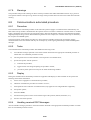
In the following set of figures examples are shown of windows that could appear on a display screen during a sending
distress automated procedure when the cancel operation is done. The first figure shows the sent distress procedure after
the transmission. The operator presses the cancel button. The second figure shows the warning with the option to
continue or to back out. The operator chooses to continue. The third figure shows the start option which still gives the
operator the option to back out. The operator selects start. The fourth figure shows the DSC phase of the cancel (the
self-addressed distress acknowledgement) which lasts only about 0,7 s on VHF. The fifth figure shows the start of the
voice cancel which provides a brief explanation to the operator. The only choice is to proceed, and in the sixth figure
the EUT provides the text of the voice cancel message that the operator can read. Upon completion of the voice cancel,
the operator returns to the distress procedure in its acknowledged state, still tuned to channel 16. Note that the operator
does have the option to repeat the procedure (perhaps instructed to do so by a coast station). That action would bring the
operator back to the fourth figure. However, once the finish option is selected, no further DSC cancels can be sent. The
seventh figure shows the return to the sending distress procedure, now in its acknowledged state. Further
communications may continue.
!! DISTRESS !! Undesignated
Waiting for reply: 0:33
Time to auto-resend: 4:09
Resend
Pause
Cancel
Undesign Undesign Undesign
Info
Sending the DSC distress cancel.
Standby for further information!
!! WARNING !!
Press ‘Start’
You are asking to cancel this distress
since it was in error or otherwise no
longer applies!
No: Don’t do.
Continue
Undesignated
to start the cancel operation.
DSC complete! Tuned to 16. You are
now to give the voice cancel
announcement. Press ‘continue’ and
read the msg.
Text of distress cancel message here
Continue
We cancelled our DISTRESS
Since 0:45
Quit
Undesi
Info
hold
Start
Do again
No: Don’t do.
Finished
Example "windows" of the
cancel distress procedure at
various stages.
Do again
The above examples are only examples. They show one means of providing the minimum required information. The
layout, method, and choice of text are up to the manufacturer.
6.4.12
Acknowledgments
The procedure shall be considered acknowledged upon reception of the first distress alert acknowledgement concerning
the same distress event.
6.4.13
Termination
Prior to acknowledgement the procedure can not be terminated either by the operator or the equipment; it may only be
cancelled by an operator initiative.
After acknowledgment, the procedure is terminated manually or by an imposed automatic timeout (not required).
However, if such an automatic timeout is provided, at least ten seconds prior to termination a visual and aural warning
that automatic termination is about to occur shall be displayed with the option to stop the termination.
6.4.14
Warnings
The procedure shall provide warnings for those reasons provided in ITU-R Recommendation M.493-12 [3], annex 4.
The operator shall have the option to go back to the stage of the procedure where the action was taken that caused the
warning.
ETSI
23
Draft ETSI EN 300 338-2 V1.3.1 (2008-12)
6.5
Receiving distress automated procedure
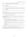
6.5.1
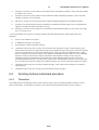
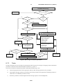
Procedure
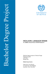
The receiving distress automated procedure is initiated either by the reception of the first multi-station distress DSC
message of a distress event, the reception of the first individually addressed distress DSC message of a distress event, or
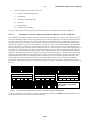
the sending of a DROBOSE. An informative schematic of the outline of the automated procedure is given in figure 2.
ETSI
24
Draft ETSI EN 300 338-2 V1.3.1 (2008-12)
INCOMING DSC
No
Allocate DSC
Yes
Same event?
Yes
Multi/indiv.
different?
No
Yes
First of type?
No
<500 nm?
polar?
Yes
Sound "manual-silence only" alarm
Sound self-terminating alarm
Get RX frequency of DSC
No
Allocate DSC
Distress alert?
Compute comms frequency
Yes
No
No
Previous alert:
different freq
in 60 s?
Yes
Comms change?
Multi frequency
8 MHz comms
Yes
Option in 10 s for: Operator
to block automatic
frequency change on HF
No
Auto change?
User choice was to
keep frequency
Yes
No
Not acked stage or
Rec. DSC is first
ack?
Yes
Make freq. change
Keep frequency
Multi station options (only):
- Send relay
- Send distress acknowledge (if
distress received)
Individual options (only):
- Send distress relay ack. (if
distress relay received)
Common options:
- Activate or place on hold
- Change comms freq (on HF)
- End Procedure
No
Rec. DSC an
ack?
Yes
Send Ack.
End procedure
Send Distress
relay
Set acked stage
No
Multi/indiv.
different?
Send DROBOSE
Figure 2: Receiving distress procedure
ETSI
Yes
Allocate DSC
25
6.5.2
Draft ETSI EN 300 338-2 V1.3.1 (2008-12)
Tasks
The radio shall follow the received distress automated procedure as shown in figure 2 complying with the automated
procedures as defined in ITU-R Recommendation M.493-12 [3], annex 4.
The received distress automated procedure shall handle the following events:
a)
the sounding of the appropriate alarms for DSC messages pertinent to the procedure;
b)
allocating all DSC messages pertinent to the station but not the procedure to their own procedures or initiating
their own procedure;
c)
on HF keeping track of the frequencies of reception;
d)
on HF appropriate tuning to the frequency and mode of subsequent communication and providing at least a
10 s warning if that tuning involves a change from the current tuning and the option to pause the tuning;
e)
on HF scanning all 6 distress frequencies;
f)
watching for the distress event acknowledgement or recognizing the self cancel;
g)
providing the operator with the option to:
6.5.3
1)
send a relay;
2)
send a distress acknowledgement (when and if a distress alert has been received);
3)
send a distress relay acknowledgement (when and if a distress relay has been received);
4)
on HF to change the frequency of subsequent communication;
5)
ability to activate or place the procedure on hold;
6)
end the procedure.
Display
During the received distress automated procedure the radio shall display or make available to the operator the following
items and/or information:
a)
the fact one is engaged in receiving a distress;
b)
the elapsed time since the procedure started (prior to acknowledgment);
c)
the elapsed time since acknowledgement (after acknowledgment);
d)
indicate whether the procedure is on hold or is active;
e)
the latest distress information (MMSI of vessel in distress, nature of distress, position, time of position,
comms);
f)
the type (alert, relay, alert acknowledgement, relay acknowledgement), sender, and intended destination
(individual, area, all ships) of the latest received DSC message;
g)
at least a 10 seconds warning before any automated change in communications frequencies are invoked in case
engaged in traffic;
h)
the frequency of subsequent communication (HF only);
i)
the frequencies on which the DSC messages have been received (HF only);
j)
displaying the valid user options;
k)
the ability to display information about the history of at least the received DSC messages pertinent to the
procedure;
ETSI
26
l)
Draft ETSI EN 300 338-2 V1.3.1 (2008-12)
and the sub-stages of the procedure which are:
1)
waiting to send acknowledgement;
2)
transmitting;
3)
waiting for acknowledgement;
4)
cancelled;
5)
acknowledged;
6)
waiting for a free channel.
At top level the elapsed time, the stage of the automated procedure, and operator options shall be displayed.
6.5.3.1
Examples of received distress procedure displays on VHF equipment
In the following set of figures examples are shown of windows that could appear on a display screen during a received
distress automated procedure at various stages during the event. The first figure show the reception of the distress alert
where the operator must silence the two-tone alarm. The display concerning the alarm text should also be flashing or
providing some type of visual alarm. The second figure shows the procedure after silencing the alarm. The procedure
indicates that channel 16 is open for traffic and that it is waiting for a distress alert acknowledgement. The third figure
shows the reception of a distress relay concerning this distress event. An alarm sounds, but it is self-terminating. The
message must still provide a means to silence it and it must flash or provide some type of visual alarm. The operator can
press "info" to view the details of the latest received DSC message pertinent to this event. The fourth figure shows the
procedure after the alarm terminates. The procedure is still waiting for the DSC acknowledgement and is still tuned to
channel 16. The fifth figure shows the reception of a repeat distress alert attempt by the vessel in distress. This attempt
could have happened automatically or been done by the operator on the vessel in distress. However, this time only the
self terminating alarm sounds. The sixth figure shows continuation of the procedure after the alarm terminates. The
seventh figure shows the reception of the distress alert acknowledgement. This time the alarm must be manually
silenced. The eighth figure shows the received distress procedure upon silencing the alarm. The DSC phase is done.
Note that the operator has the option to exit the procedure, place it on hold, or get further information at any time during
the event.
!! Rx Distress from 343444332 !!
Info
Quit
Hold
Silence
!! Rx Distress from 343444332 !!
Rx Relay about 343444332
Waiting for coast stn! 0:23
Since 5:55
Quit
Info
Hold
Relay
Ack
Info
Hold
Silence*
Rx Relay about 343444332
Repeat Distress from 343444332
Repeat Distress from 343444332
Waiting for coast stn! 6:00
Since 8:07
Waiting coast stn! 8:12
Quit
Info
Hold
Relay
Ack
Info
Quit
Hold
Silence*
Distress from 343444332 acked
Distress from 343444332 acked
Since 0:02
Coast stn replied! 0:23
Quit
NOTE:
Quit
Undesi
Info
Hold
Silence
Quit
Undesign
Info
Hold
Quit
Info
Hold
Relay
Ack
Example “windows” of the
received distress automated
procedure .
*This alarm self terminates in one second. After this the option shall disappear.
The above examples are only examples. They show one means of providing the minimum required information. The
layout, method, and choice of text are up to the manufacturer.
ETSI
27
6.5.4
Draft ETSI EN 300 338-2 V1.3.1 (2008-12)
Handling received DSC Messages
DSC messages pertinent to the station but not the procedure shall be allocated to the appropriate automated procedure
or initiate their own automated procedure on hold.
DSC messages that are pertinent to the procedure are all DSC messages concerning the same distress event. If the
MMSI is unknown, DSC messages that are pertinent to the procedure are all DSC messages that have the same distress
information (nature of distress and subsequent communication - allow updated position and time). However,
individually addressed DSC messages shall initiate their own automated procedures on hold if engaged in a received
distress procedure handling multi-station (for example, all ships, area) addressed DSC messages or vice versa.
6.5.5
Alarms
In a given procedure, only the reception of the initial DSC message and the DSC message that first acknowledges the
procedure shall sound an alarm unique to the DSC message type (with the two-tone sound reserved for the distress alert
or relay if it initiates the procedure) which shall be manually silenced.
All subsequent DSC messages that are pertinent to the procedure shall sound the self terminating alarm.
6.5.6
Determining Subsequent communications
On VHF it is always channel 16.
On MF it is either 2 182,0 kHz (voice) or 2 174,5 kHz (data).
On HF the frequency band is given by:
a)
the frequency band of a single frequency distress alert attempt, relay, distress alert acknowledgement, and
relay acknowledgment;
b)
the 8 MHz band if a multi-frequency distress alert attempt is received. A distress alert attempt is considered to
be multi-frequency if two consecutive distress alerts are received on two different frequencies within a period
of one minute. This rule applies even if neither of the two distress alerts were received on the 8 MHz band;
c)
the channel set is given by the mode of subsequent communication;
d)
the band of subsequent communication given in (c) shall be used as the default DSC band for any subsequent
distress DSC messages sent by the operator.
6.5.7
Automated tuning
The tuning to the subsequent communication frequencies as determined in clause 6.5.6 shall occur automatically upon
reception of a distress DSC message in the following manner:
a)
on HF the operator shall have a 10 seconds warning prior any tuning if the new subsequent frequency is
different from the current;
b)
the operator shall be able to pause the tuning in case engaged in traffic or accept the tuning;
c)
prior to acknowledgement, the tuning to the new frequency shall occur in the absence of any operator action;
d)
after acknowledgment the tuning to the new frequency shall only occur if the operator requests it (note that the
procedure is not yet acknowledged until after the first acknowledgement starts the alarm).
6.5.8
Acknowledgments
The procedure handling all-ships and area distress DSC messages and distress alerts shall be considered acknowledged
upon reception of the first distress alert acknowledgement or all ships distress relay acknowledgement.
A distress alert acknowledgement sent by the vessel in distress shall be recognized as a self cancel.
The procedure handling a received individually addressed distress relay shall be considered acknowledged when the
operator first transmits the corresponding individually addressed distress relay acknowledgement to the sender.
ETSI
28
Draft ETSI EN 300 338-2 V1.3.1 (2008-12)
The procedure handling a distress relay sent to an individual station shall be considered acknowledged when the first
corresponding individually addressed distress relay acknowledgement is received from that station.
6.5.9
Sending Relays and Acknowledgments
On HF the operator shall always have the option to send a distress relay to a coast station.
The operator shall not have the option to send a distress relay acknowledgment until an individual distress relay request
has been received.
The operator shall not have the option to send a distress alert acknowledgment until a distress alert has been received.
Once the option to send any of the distress DSC messages (distress relay, distress alert acknowledgement, distress relay
acknowledgement) referenced above becomes available, the options shall remain available until the procedure is
terminated.
The procedure shall automatically compose the distress DSC messages referenced above except:
a)
the distress relay where the operator shall have the option to select the addressing mode and address where the
default shall be individual and on MF/HF the communications mode, and
b)
in a procedure handling an individually addressed relay or relay acknowledgement, the operator shall have the
option to send an all ships relay acknowledgement in addition to the default individual relay acknowledgement
even though this DSC message is typically forbidden to be sent by ship stations. (Note that it is only possible
to send an individually addressed distress relay acknowledgement upon reception of an individually addressed
relay).
On HF the operator shall have the option to override the default band of the DSC message and send the distress DSC
messages (distress relay, distress alert acknowledgement, distress relay acknowledgement) referenced above on any one
of the six distress channels.
6.5.10
Termination
The procedure can be terminated manually or by the automated timeout. At least ten seconds prior to automated
termination, a visual and discrete aural warning shall be displayed with the option to stop the automatic termination.
If the procedure is terminated manually by the user then integrated equipment may revert to the channel or frequency
that was previously selected before the DSC procedure.
6.5.11
Warnings
The procedure shall provide warnings for those reasons provided in ITU-R Recommendation M.493-12 [3], annex 4.
The operator shall have the option to go back to the stage of the procedure where the action was taken that caused the
warning.
6.6
Sending non distress automated procedure
6.6.1
Procedure
The sending non distress automated procedure results when the operator selects to transmit a DSC message that does
not contain the distress information. It also results when an acknowledgement to a sending non distress automated
procedure that has been prematurely terminated is received ("an acknowledgement one quit waiting for"). An
informative schematic of the outline of the automated procedure is given in figure 3.
ETSI
29
Draft ETSI EN 300 338-2 V1.3.1 (2008-12)
Select to Send DSC Message
Transmit DSC message
No
Require ack?
Yes
HF: Tune radio to ack freq
Enter "acked" stage.
Present Options:
- Resend DSC (unless ack received.)
- On hold/activate
- End Procedure
Tune radio for comms
or display information
Sound
ack alarm
No
Acked
stage?
Yes
Yes
Yes
Pertinent
to proc.?
Receive
DSC?
No
No
allocate DSC message
End Procedure
Figure 3: Sending non distress automated procedure
6.6.2
Tasks
The radio shall follow the sending non distress automated procedure as shown in figure 3 complying with the automated
procedures as defined in ITU-R Recommendation M.493-12 [3], annex 4.
The sending non distress automated procedure shall handle the following events:
a)
prior to acknowledgement:
1)
the transmission of the composed/selected DSC message;
2)
if the DSC message demands no acknowledgment setting the procedure to acknowledged;
3)
if the DSC message demands an acknowledgement:
i)
on HF tuning the general receiver to the frequency of the DSC acknowledgement if required;
ii)
waiting for the acknowledgement and alarming when received;
iii)
allocating any received DSC message not pertinent to the procedure to their appropriate procedure
or initiating their own procedure on hold;
iv)
providing the valid operator options which are:
resend the initial DSC message;
activate or place the procedure on hold;
terminate the procedure;
ETSI
30
b)
Draft ETSI EN 300 338-2 V1.3.1 (2008-12)
upon reception of the acknowledgement or being set to acknowledged:
1)
tuning the general receiver and transmitter to the frequency of subsequent communication or displaying
the requested information;
2)
ignoring any received DSC message pertinent to the procedure since it is a duplicate;
3)
allocating any received DSC message not pertinent to the procedure to the appropriate procedure or
initiating their own procedure on hold; and
4)
providing the valid operator options which are:
6.6.3
i)
resend the initial DSC message if it requires no acknowledgement;
ii)
activate or place the procedure on hold;
iii)
terminate the procedure.
Display
During the sending non distress automated procedure the radio shall display or make available to the operator the
following items and/or information:
a)
the fact one is engaged in sending a non distress DSC message;
b)
the elapsed time since sending the initial DSC message (prior to acknowledgement); or
c)
the elapsed time since being acknowledged (once acknowledged or considered acknowledged);
d)
the information content of the initial DSC message sent which is:
e)
1)
the type of DSC message (description);
2)
the priority of the DSC message;
3)
the destination;
4)
the means of subsequent communication or purpose;
5)
the frequencies of subsequent communication if any;
6)
on HF the frequency of the sent DSC message;
7)
whether or not the DSC message requires an acknowledgement;
if acknowledged, the information content of the acknowledgement which is:
1)
the type of acknowledgment (description);
2)
the priority of the DSC acknowledgement;
3)
the sender;
4)
to whom the DSC acknowledgement was sent;
5)
the means of subsequent communication or the requested information;
6)
if appropriate the mode/frequency change or unable to comply and reason;
7)
the frequencies of subsequent communication if any;
8)
on HF the frequency of the acknowledgement;
f)
the valid operator options; and
g)
the sub-stages of the procedure which are:
1)
waiting for free channel;
ETSI
31
2)
transmitting;
3)
waiting for acknowledgement;
4)
linked for communications;
5)
procedure done (no more to do).
Draft ETSI EN 300 338-2 V1.3.1 (2008-12)
At top level the elapsed time, the stage of the automated procedure, and operator options shall be displayed.
6.6.3.1
Examples of sending non distress procedures displays on VHF equipment
In the following figure is a set of example windows that could appear on a display screen during a sending non distress
procedure. The examples below show windows for a routine call (1-4), group call (5 and 6), and an urgency call (7 and
8).
Calling 456444322
Calling 456444322
Calling 456444322
Transmitting
Waiting for 456444322 to reply: 0:11
Reply received
Quit
Undesign
Hold
Quit
Undesign
Info
Hold
Calling 456444322
Group call to 099988877
Channel 72 ready for talk! 0:02
Transmitting
Quit
Undesign
Info
Hold
Quit
Undesign
Info
Urgency call to all stations!
Transmitting
Channel 9 tuned for broadcast: 0:12
Info
Hold
Quit
Undesign
Info
Quit
Undesign
Info
Hold
Silence
Group call to 099988877
Channel 6 ready for talk! 0:25
Hold
Urgency call to all stations!
Quit
Undesign
6.6.4
Info
Hold
Quit
Undesign
Info
Hold
Example "windows" of the
sending non distress
procedures .
Handling received DSC Messages
DSC messages pertinent to the station but not the procedure shall be allocated to the appropriate automated procedure
or initiate their own automated procedure on hold.
DSC messages that are pertinent to the procedure are acknowledgements to the initial DSC message.
6.6.5
Alarms
The reception of the first acknowledgement pertinent to the procedure shall sound the appropriate acknowledgement
alarm as specified in tables D.1 and D.2.
Any subsequent acknowledgement may be ignored as only individually addressed non distress DSC messages have
acknowledgements.
6.6.6
Automated tuning
On HF, DSC messages using the duplex DSC channels requiring acknowledgements shall tune the general receiver to
the anticipated frequency of the DSC acknowledgement.
If the DSC message requires subsequent communications, the general receiver and transmitter shall be tuned to the
frequencies given in the acknowledgement upon reception of the "able to comply" acknowledgement.
If the acknowledgement received is "unable to comply" the radio shall not tune to the originally proposed channel or
frequency.
If the acknowledgement received is "able to comply" but proposes a new working frequency that is not available the
radio shall not tune to the proposed frequency, but inform the operator that he has to make a new call request to the
called station.
ETSI
32
Draft ETSI EN 300 338-2 V1.3.1 (2008-12)
If no acknowledgement is required the transmitter shall be tuned to the frequency of subsequent communications given
by the initial DSC message.
6.6.7
Delayed Acknowledgements
If an acknowledgement to a sending non distress automated procedure is received after the procedure has been
prematurely terminated, the automated procedure shall initiate itself recreating the initial DSC message based upon the
acknowledgement. The procedure shall inform the operator that "an acknowledgement we quit waiting for" has been
received. If the acknowledging station changed the frequency or communication mode, the original values will not be
known but shall be assumed to be that present in the acknowledgement. If the acknowledging station responded with
"unable to comply" all the original communication information will be unknown in which case the initial DSC message
shall be assumed to have been radiotelephone on any legal frequency.
6.6.8
Termination
Termination is done manually or by the automated timeout. At least ten seconds prior to automated termination, a visual
and discrete aural warning shall be displayed with the option to stop the automatic termination.
If the procedure is terminated manually by the user then integrated equipment may revert to the channel or frequency
that was previously selected before the DSC procedure.
6.6.9
Warnings
The procedure shall provide warnings for those reasons provided in ITU-R Recommendation M.493-12 [3], annex 4.
The operator shall have the option to go back to the stage of the procedure where the action was taken that caused the
warning.
6.7
Receiving non distress automated procedure
6.7.1
Procedure
The received non distress automated procedure results when a DSC message is received that does not contain the
distress information and is not an acknowledgement. An informative schematic of the outline of the automated
procedure is given in figure 4.
ETSI
33
Draft ETSI EN 300 338-2 V1.3.1 (2008-12)
INCOMING DSC Message
No
allocate
Relevant to procedure?
Yes
No
No
Ack req?
Yes
Acked
stage?
Yes
No
Able?
Turn off "able" option
Yes
No
Auto ack?
Yes
1st call: Sound "manual" alarm
after: sound self-terminating alarm
Send ack
Yes
Options (if not acked):
- able to comply (if able)
- comply with change
- unable to comply
- on hold/activate
- end procedure
Unable was
transmitted?
No
Remove
"able" option
Options (if acked):
- resend acknowledgement
- on hold/activate
- end procedure
Remove "unable" and
"comply with change"
user options
Yes
Auto ack
stage?
No
No
Set event/stage acked
Comms?
Yes
Tune to comms
End procedure
Auto ack
stage?
Autom. silenced alarm after sending
No
End procedure
Yes
Figure 4: Receiving non distress procedure
6.7.2
Tasks
The radio shall follow the received distress automated procedure as shown in the figure 4 complying with the automated
procedures as defined in ITU-R Recommendation M.493-12 [3], annex 4.
The received non distress automated procedure shall handle the following events:
a)
sound the appropriate alarms at the appropriate times for DSC messages pertinent to the procedure;
b)
allocate DSC messages pertinent to the station but not the procedure to the appropriate automated procedure or
initiate their own automated procedure on hold;
c)
denote the procedure as acknowledged if the DSC message requires no acknowledgement;
ETSI
34
Draft ETSI EN 300 338-2 V1.3.1 (2008-12)
d)
provide and compose the acknowledgement options as dictated by the initial DSC message;
e)
on HF tune the transmitter to the appropriate DSC frequency for any selected acknowledgement if an
acknowledgement is required;
f)
tune the general receiver and transmitter to the frequencies of subsequent communications when and if
required;
g)
provide the operator with the option to:
1)
2)
6.7.3
prior to acknowledgment:
i)
comply if able;
ii)
comply with mode or frequency change if there are communications;
iii)
unable to comply;
iv)
ability to activate or place the procedure on hold;
v)
end the procedure;
after acknowledgement or being considered acknowledged:
i)
resend the acknowledgment (after sending the first acknowledgment);
ii)
ability to activate or place the procedure on hold;
iii)
end the procedure.
Display
During the received non distress automated procedure the radio shall display or make available to the operator the
following items and/or information:
a)
the fact one is engaged in receiving a non distress DSC message;
b)
the elapsed time since the procedure started (prior to acknowledgment); or
c)
the elapsed time since acknowledgement (after acknowledgment);
d)
indicate whether the procedure is on hold or is active;
e)
at least a 10 s warning before any automated change in communications frequencies are invoked in case
engaged in traffic;
f)
the information content of the received DSC message:
g)
1)
priority (category);
2)
the sender;
3)
to whom the DSC message was sent (format and MMSI or area);
4)
means of subsequent communication or the requested or sent information;
5)
frequencies and mode of subsequent communication (if any);
6)
on HF the frequency of the DSC message;
7)
whether or not the DSC message requires an acknowledgement;
the information content of any acknowledgment sent:
1)
priority;
2)
the destination;
ETSI
35
Draft ETSI EN 300 338-2 V1.3.1 (2008-12)
3)
the communication mode and frequencies, or unable to comply and reason or info;
4)
on HF the frequency of the acknowledgment;
h)
displaying the valid user options; and
i)
the sub-stages of the procedure which are:
1)
waiting to send acknowledgement;
2)
transmitting;
3)
acknowledged;
4)
waiting for a free channel.
At top level the elapsed time, the stage of the automated procedure, and operator options shall be displayed.
6.7.3.1
Examples of receiving non distress procedures displays on VHF equipment
In the following figure is a set of example windows that could appear on a display screen during a received non distress
procedure. The examples below show windows for a received routine call, group call, and an urgency call.
Rx Call from 456444322
Rx Call from 456444322
Silence
Quit Reply
Undes
Info
change
Hold
Rx Call from 456444322
Waiting for you to reply, 1:44
Quit Reply
Undes
change
Info
Transmitting
Hold
User receives call. Alarm sounds. User
silences alarm.
Waiting for user to reply. User presses
reply button.
Rx Call from 456444322
Rx group call to 099988877
Channel 72 ready for talk! 0:12
Info
Silence
Hold
User receives group call. Alarm sounds.
User silences alarm.
Rx all stations Urgency call !
Rx all stations Urgency call !
Channel 9 tuned for broadcast, 0:33
6.7.4
Info
Hold
Silence
Rx group call to 099988877
Now listening on Channel 6! 1:01
Quit
Undes
Quit
Reply Info
Hold
Undes
Procedure tunes to channel and indicates
the link is ready for talk. Reply possible
Quit
Undes
Quit Reply change Info
Hold
Undes
Procedure indicates VHF is transmitting.
Quit
Undes
Info
Hold
Quit
Undes
Info
Hold
Not much to do here. Link is one way.
Procedure indicates link is ready.
Example "windows" of the
received non distress
procedures .
Handling received DSC messages
DSC messages pertinent to the station but not the procedure shall be allocated to the appropriate automated procedure
or initiate their own automated procedure on hold.
DSC messages that are pertinent to the procedure are repeats of the initial DSC message.
6.7.5
Alarms
When auto acknowledging position, poll and test DSC messages no alarm shall sound.
When auto acknowledging individually addressed DSC messages requesting subsequent communications, an alarm
shall sound and be terminated as specified in tables D.1 and D.2, but the alarm shall be delayed until after transmission
of the acknowledgement.
When auto acknowledging is not involved, an alarm shall sound and be terminated as specified in tables D.1 and D.2.
All repeat initial DSC messages shall sound the self-terminating alarm.
ETSI
36
6.7.6
Draft ETSI EN 300 338-2 V1.3.1 (2008-12)
Automated tuning
DSC messages requiring acknowledgements shall determine the frequency of the DSC acknowledgement based upon
the frequency of the received DSC message. If the channel of the DSC message cannot be determined, the
acknowledgment shall be sent on the same frequency as the original DSC message was received (HF only).
If the DSC message requires subsequent communications, the general receiver and transmitter shall be tuned to the
frequencies of the subsequent communications given in the acknowledgement if acknowledgments are requested.
Otherwise the general receiver shall be tuned to the frequency of subsequent communication given by the initial DSC
message:
a)
the operator shall have a 10 seconds warning prior to any tuning if the new subsequent frequency is different
from the current;
b)
the operator shall be able to pause the tuning or accept the tuning.
6.7.7
Acknowledgments
Acknowledgment options shall only be provided if the initial DSC message requests an acknowledgement and the
acknowledgment option is possible. For example, the "able to comply" option is not possible for an individually
addressed DSC message requesting telephony but providing no subsequent communication frequency information. Only
the "comply with mode/frequency change" and "unable to comply" options are possible.
In the case of a received individual call requesting telephony, the radio shall be capable of identifying if the requested
working frequency identified in the call is available in the equipment:
-
If this frequency is available the radio shall display the call details and compose an "Able to comply"
acknowledgement which shall only be transmitted manually. Switching to the frequency identified shall only
be performed after a manual "Able to comply" acknowledgement has been transmitted.
-
If this frequency is not available the radio shall display the call details and compose an "Unable to comply"
acknowledgement with 104 as the first telecommand and 108 as the second telecommand. This
acknowledgement may be automatic.
The "able to comply" option shall only require a single action by the operator to respond (e.g. lifting the handset). The
operator shall not be required to compose any elements of this acknowledgement.
The "comply with mode/frequency change" option shall require that the operator be able to enter/select frequencies
and/or channels and on HF between voice and data modes before sending. The operator shall not be required to
compose any other elements of this acknowledgement.
The "unable to comply" option shall require that the operator select one of the 10 reasons (telecommand 2 symbols, 101
does not apply to ship stations) specified in ITU-R recommendation M.493-12 [3] for being unable to comply (default
"no reason given") before sending. In the case of a position request, the option shall only require a single action by the
operator to send, and the procedure shall indicate non compliance by filling the position and time information with the
no information character.
If an acknowledgement is resent by the operator it shall be identical to the first acknowledgment. It shall not be possible
to further edit the content.
6.7.8
Termination
When auto acknowledging position, poll and test DSC messages the procedure shall self-terminate after sending the
acknowledgement.
When sending an "unable to comply" acknowledgement the procedure shall terminate after completing the
transmission.
In all other cases, termination is done manually or by the automated timeout. At least ten seconds prior to automated
termination, a visual and discrete aural warning shall be displayed with the option to stop the automatic termination.
If the procedure is terminated manually by the user then integrated equipment may revert to the channel or frequency
that was previously selected before the DSC procedure.
ETSI
37
6.7.9
Draft ETSI EN 300 338-2 V1.3.1 (2008-12)
Warnings
The procedure shall provide warnings for those reasons provided in ITU-R Recommendation M.493-12 [3], annex 4.
The operator shall have the option to go back to the stage of the procedure where the action was taken that caused the
warning.
6.8
Communications automated procedure
6.8.1
Procedure
The communications automated procedure results when the operator engages in communications established by non
DSC means. The procedure is initiated when the operator chooses to monitor a channel for non DSC traffic or non DSC
traffic is initiated by the reception of an appropriate signal. (Note that the details in design of the automated procedure
might depend upon the type of non DSC traffic being monitored. For example, the non DSC traffic may be initiated by
the reception of an NBDP signal).
The critical purpose of this simple procedure is to assure that received DSC messages do not interrupt ongoing
communications in the same manner that they do not disrupt any of the ongoing automated procedures handling DSC
messages.
6.8.2
Tasks
The communications automated procedure shall handle the following events:
a)
received DSC messages pertinent to the station shall be allocated to the appropriate automated procedure or
initiate their own automated procedure on hold;
b)
tune the general receiver and transmitter to the frequencies of communication;
c)
provide the operator with the option to:
6.8.3
1)
terminate the procedure;
2)
toggle between activating and placing the procedure on hold;
3)
provide any other options necessary for the traffic mode being handled.
Display
During the communications automated procedure the equipment shall display or make available to the operator the
following items and/or information:
a)
the fact one is engaged in a communications procedure;
b)
indication of whether the procedure is on hold or is active;
c)
the frequencies and or channels of communication (only applies for non-integrated DSC equipment);
d)
the operator options;
e)
the station MMSI;
f)
the latest known position of the vessel and the origin of the position (manual, automatic, etc.);
g)
the UTC time of that position.
6.8.4
Handling received DSC Messages
All received DSC messages pertinent to the station shall be allocated to the appropriate automated procedure or initiate
their own automated procedure on hold.
ETSI
38
6.8.5
Draft ETSI EN 300 338-2 V1.3.1 (2008-12)
Tuning of the general receiver and transmitter
The procedure shall automatically tune the general receiver and transmitter to the frequencies of the selected channel.
6.8.6
Termination
The procedure may either be terminated manually or via an automatic timeout.
6.9
Multiple automated procedures and parallel event handling
6.9.1
Procedure
This clause describes the handling of received DSC messages that are pertinent to the station while the radio is engaged.
6.9.2
Tasks
If the radio is engaged in handling an automated procedure (except for an unacknowledged sending distress automated
procedure), received DSC messages that are pertinent to the station but not the currently active automated procedure:
a)
are allocated to an existing automated procedure on hold; or
b)
shall initiate their own automated procedure on hold.
Only one automated procedure can be active at a time (since there is only one transmitter and general receiver in
addition to the watch receiver) thus any action to activate an automated procedure on hold places the currently active
automated procedure on hold.
Automated procedures on hold shall behave identical to active procedures except they do not have control of the
transmitter and general receiver thus:
a)
the only operator options which are available are those that do not require use of the transmitter or general
receiver such as to terminate or activate the automated procedure;
b)
any subsequent tunings of the transmitter and general receiver that would occur if the procedure were active
upon reception of a DSC message appropriate to the procedure shall not occur until the procedure is activated
by the operator;
c)
the display of automated procedures on hold may be requested by a simple button press or selection, and may
be represented by an appropriately named list, labelled icons, or equivalent in order to minimize space
requirements;
d)
all other features, including handling of the alarms and full display of information at the request of the
operator, remain.
The operator shall be able to activate any displayed automated procedure on hold selected from the list in c) by a single
action (a button press or selection) unless the currently active procedure is transmitting,
If the only remaining automated procedures present on the equipment are inactive or on hold, and there are automated
procedures handling test, polling, or position requests and these procedures are setup to auto acknowledge, the
equipment shall successively perform the auto acknowledgement and terminate these procedures.
ETSI
39
Draft ETSI EN 300 338-2 V1.3.1 (2008-12)
The radio shall provide sufficient memory or capacity to be able to handle a minimum of seven simultaneous automated
procedures including a reserve of one. If the equipment can handle more than the required minimum, the equipment
shall provide a setup option where the operator can set the value to seven (or any other value the equipment is capable
of handling). This option is only required for equipment that can handle more than the minimum. When the equipment
maximum is exceeded by one and the reserve procedure is started, the equipment shall generate a warning stating that
an automated procedure needs to be terminated or equivalent, though this new procedure and all the previous automated
procedures shall still function normally. At this time, the operator shall be prevented from starting any automated
procedure except for the sending one's own distress. If the operator does not elect to terminate an automated procedure,
the reception of an additional automated procedure shall result in the automatic termination of an existing automated
procedure.
The automatic and immediate termination of an automated procedure should be based upon age and priority.
NOTE:
6.9.3
Automated procedures handling received Poll, position and test calls shall always be the first procedures
to terminate, regardless of their age.
Examples of multiple procedure screens
In the following figure is a set of example windows displaying multiple procedures. In this case one area of the screen is
dedicated to displaying the active procedure and a list of current procedures is navigated by up/down arrow keys. In the
first figure the received distress procedure is shown. The procedure is unacknowledged, and upon activating this
procedure the EUT automatically tunes the subsequent communication channel to 16. The second figure shows the
result of pressing the "up arrow". The received distress procedure goes on hold and our sending non distress procedure
becomes active. Note that 555444322 has not responded yet. The default is for 555444322 to auto acknowledge, but it
may not happen because 555444322 is out of range or engaged in another communication event and has not gotten
around to acknowledging your call. The third figure shows the result of pressing the "up arrow" key one more time. The
sending non distress procedure goes on hold and the listed received non distress procedure which happens to be a group
call becomes active. The channel of subsequent communication automatically tunes to channel 6 and one can join in the
voice traffic of that group. Of course the operator missed any traffic associated with that procedure while the procedure
was on hold.
The fourth figure shows what might happen if 555444322 acknowledges our individual call while another procedure is
active. The "procedure list bar" might flash as the alarm sounds indicating it needs attention, or a popup message could
be displayed. In either case the operator must be presented with the reason for and means of silencing the alarm so one
does not have to activate the procedure. In this case the operator opted to press the down arrow to activate the indicated
procedure. The fifth figure shows the result and the operator can now silence the alarm while "in" the procedure.
ETSI
40
Draft ETSI EN 300 338-2 V1.3.1 (2008-12)
!! Rx Distress from 222333121 !!
Calling 555444322
Rx group call to 089934344
Waiting for coast stn! 4:08
Wait for 555444322 to reply – 1:11
Listening on channel 6 – 3:45
Quit
Undes
Info
Hold
Hold
Info
Quit
Undes
Quit
Undes
Info
Hold
Rx call from 456444322
Rx call from 456444322
Rx call from 456444322
Rx group call from 699343444
Rx group call from 699343444
Rx group call from 699343444
Calling 555444322
Calling 555444322
Calling 555444322
Rx Distress from 222333121
Rx Distress from 222333121
Rx Distress from 222333121
Talking on channel 6
Talking on channel 6
Talking on channel 72
Rx group call to 089934344
Calling 555444322
Listening on channel 6 – 7:43
Quit
Undes
Info
Hold
Reply! 0:02
Quit
Undes
Info
Hold
Silence
Rx call from 456444322
Rx call from 456444322
Rx group call from 699343444
Rx group call from 699343444
Reply! Any key stops alarm
Calling 555444322
Rx Distress from 222333121
Rx Distress from 222333121
Talking on channel 72
Talking on channel 72
NOTE:
The "procedure buttons" could very
well be physical buttons that are not
part of the screen, similar to many
older telephones. How the
manufacturer chooses to handle the
browsing of the multiple procedures
is not specified by this test standard.
The manufacturer has in this example provided the hold function separately allowing the user to view an
inactive procedure without putting the current active procedure on hold.
ETSI
41
Draft ETSI EN 300 338-2 V1.3.1 (2008-12)
Annex A (normative):
DSC Message Composition
A.1
Default values
When default parameters are necessary, the factory default values shall be as shown in figure A.1.
Loading DSC Defaults
Is the format
editable?
Yes
Controller sets: Individual (see note 1)
No
Controller sets MMSI or group MMSI to an invalid indicator OR
controller sets area to 500 nm centered on ship¹
telecommand
editable?
Yes
Controller sets: Radio telephone (see note 1)
No
Is the category
editable?
Yes
Controller sets: Routine or Safety (see note 2)
No
Is the comms
chan. editable?
Yes
Controller sets: a non distress channel (see note 1)
No
Is the DSC chan.
editable?
Yes
Controller sets: freq to 2 MHz band (see note 1)
No
All other parameters are never editable
NOTE 1: Only if the parameter has not already been set by the operator.
NOTE 2: The default is "routine" if allowed (it is not allowed for area or all ships messages), otherwise the default is
"safety". This default is to be reset (the most recently entered value shall be overwritten) when the operator
selects the option to compose a non distress DSC message at some later time.
Figure A.1: Loading DSC defaults
ETSI
42
A.2
Draft ETSI EN 300 338-2 V1.3.1 (2008-12)
The default DROBOSE
Table A.1: Default DROBOSE
vessel in
Format
Nature
Distress
distress MMSI
(see note)
comms
unknown
Individual
Undesignated
Phone
NOTE:
The destination MMSI shall be some invalid indicator.
position
unknown
UTC time of
position
unknown
The MMSI of the vessel in distress, format, nature and position shall be reset when the operator selects the option to
compose the DROBOSE at some later time.
A.3
Allowable non distress DSC message parameters
The radio shall provide the operator only with the ability to send non distress DSC messages with the parameter
combinations as given by table 4 in the latest ITU-R recommendation M.493-12 [3]. For convenience, the allowable
parameter combinations for the various message types for non distress DSC messages are summarized in table A.2.
Parameters in bold type are fixed for that DSC message type and when composing that message type, the fixed
parameters shall not be able to be edited by the operator.
Table A.2: Allowable parameter combinations
Message type
Format
Category
Telecommand
Frequency
(note 1)
message
Individual
Safety
General priority
Area (note 2),
Phone, HF: NBDP
Comms freq (note 5)
urgency
All-ships (note 3)
Individual
Routine
Individual routine
Phone, HF: NBDP
Comms freq (note 5)
Group
Routine
Group DSC
Phone, HF: NBDP
Comms freq (note 5)
Individual
Safety
Position request
No info
Position request
Individual
Safety
Test
No info
Test
Area (note 2),
Medical Transport
Urgency
Phone, HF: NBDP
Comms freq (note 5)
All-ships (note 3)
(note 4)
Area (note 2),
Urgency
Neutral Craft (note 4)
Phone, HF: NBDP
Comms freq (note 5)
All-ships (note 3)
NOTE 1: The ability to enter/select an appropriate address for the individual, area, and group formats is also
necessary.
NOTE 2: MF/HF only.
NOTE 3: VHF only.
NOTE 4: The Medical Transport and Neutral Craft DSC messages shall only be available as a setup option. In
the factory defaults, these DSC messages shall not be available.
NOTE 5: On MF/HF the communications options are the duplex and simplex radio phone and NBDP
channels/frequencies. On VHF the communication options are the voice channels 1 to 28 and 60 to 86
excluding 70, 75, and 76. A broadcast option is also permissible. For individually addressed DSC
messages, there is also the option of letting the other station decide. When directed to a coast station
the radio shall let the coast station decide the working frequencies. On MF/HF the ship station shall
provide position information in place of the frequency message. On VHF the ship station may put the
"no information" characters in the frequency message.
ETSI
43
Draft ETSI EN 300 338-2 V1.3.1 (2008-12)
Annex B (normative):
Radius-Centre point conversion and rounding algorithm
B.1
Radius-centre point conversion
The Mercator box specification coded into the DSC message shall be the minimum sized box that encompasses the
entire circle as illustrated in figure B.1.
(33 S, 63 W)
31 S
65 W
63 W
61 W
57 W
59 W
δ lon = 3º 12’
lat-lon box after rounding
radius
80 nm =
33 S
1º 20’ lat =
1º 36’ lon
ship
δ lat =
(33º 9’ S,
2º 40’
δ lat
= 4º
61º 10’W)
lat-lon box before rounding
35 S
δ lon = 4º
Figure B.1: Circle-radius to lat-lon box
The centre point, radius to northwest corner point, latitude-longitude Mercator box conversion shall take the following
steps. The situation shown in figure B.1, a radius of 80 nautical miles cantered on the point (33º 9'S, 61º 10'W) is used
as an example in the conversion algorithm below as an illustration.
a)
Define the centre point as given by the latitude - longitude point (θ, λ): (33º 9'S, 61º 10'W).
b)
The radius shall be converted to units of latitude φ: (80 nautical miles = 1º 20" latitude).
c)
The equivalent value in units of longitude shall be given by: γ = φ /cosθ, where θ is the latitude of the centre
point: 1º 36' longitude = 1º 20' latitude/cos(33º 9'). If the longitude exceeds 49º 00', the longitude shall be
truncated to that value since the maximum box width in the DSC sentence is 99º.
d)
The dimensions of the Mercator box before rounding shall be given by (2φ, 2γ): (2º 40', 3º 12').
e)
The northwest corner point of the Mercator box before rounding shall be given by moving the centre point
latitude north by the radius distance φ and the centre point longitude west by the radius distance γ:
(33º 9'S + 1º 20'N, 61º 10'W + 1º 36'W) = (31º 49'S, 62º 46'W).
ETSI
44
B.2
Draft ETSI EN 300 338-2 V1.3.1 (2008-12)
Rounding
If the enhanced geographic position expansion option is not used, the northwest corner point and Mercator box
dimensions shall be rounded. The rounding shall take place as follows:
a)
The northwest corner point latitude shall be moved northward to the nearest whole degree latitude and the
longitude shall be moved westward to the nearest whole degree longitude.
b)
31º 49'S becomes 31º S, a movement of 49'N and 62º 46'W becomes 63º W, a movement of 14'W.
c)
The northward and westward movements needed to round the northwest corner point to whole degrees shall be
added to the latitude height and longitude width of the Mercator box: (2º 40' + 49', 3º 12' + 14') =
(3º 29', 3º 26').
d)
The final dimensions of the Mercator box shall be rounded upward to the nearest whole degree: (4º, 4º).
B.3
Special cases for either form of area data entry
a)
If the final northwest corner point via either entry method exceeds 90ºN it shall be truncated to 90ºN and the
latitude height of the Mercator box shall be adjusted accordingly.
b)
If the final southern extent of the Mercator box via either entry method exceeds 90ºS the latitude height shall
be truncated so that it reaches 90ºS.
c)
If the final longitudinal dimension exceeds 99º, the dimension shall be truncated to 99º.
d)
If the final latitudinal dimension exceeds 99º, the dimension shall be truncated to 99º.
ETSI
45
Draft ETSI EN 300 338-2 V1.3.1 (2008-12)
Annex C (normative):
Automated Non Distress Channel/Frequency Selection
Algorithm
Automated subsequent communications channel selection provides a default channel for the operator for non distress
DSC messages requiring subsequent communications based upon a simple algorithm. It shall be applied in the absence
of any other specialized means of an automated communication setup, such as HF Automatic Linking Exchange (ALE).
C.1
VHF
a)
Channel 16 shall not be used as a default for routine category DSC messages.
b)
If the DSC message is directed toward ship stations, a simplex channel shall be used (for example channel 6).
c)
DSC messages directed toward a coast station shall let the coast station decide (position or all 126 s in the
frequency parameters of the DSC message).
d)
Any automatically proposed channel or list of channels may be established as an operator or configuration
option.
C.2
HF
On HF one has several bands of simplex and duplex frequencies for both voice or analogue signals (3 000 Hz
bandwidth) and data signals (500 Hz bandwidth):
a)
The distress channels shall not be used for routine category DSC messages.
b)
The band of the communication channel shall be in the band of the DSC message.
c)
The set of 3 000 Hz analogue channels shall be chosen for voice communications.
d)
The set of 500 Hz data (NBDP) channels shall be chosen for data modes such as NBDP.
e)
DSC messages addressed to coast station destinations shall let the coast station decide (position in the
frequency parameters of the DSC message).
f)
DSC messages addressed to ship station destinations shall use the simplex set of channels.
g)
DSC messages directed to a group or an area shall use the broadcast mode (126 s for the TX frequency in the
frequency parameters of the DSC message).
h)
On HF the band of the communication channel shall be in the band of the DSC message.
i)
On HF the telephony channel set shall be chosen for voice communications.
The automated channel/frequency selection shall be able to be overridden (which will be necessary to select a distress
channel for subsequent communications).
ETSI
46
Draft ETSI EN 300 338-2 V1.3.1 (2008-12)
Annex D (normative):
Alarms
D.1
Alarm specifications
Table D.1 summarizes the alarm characteristics required by the radio. The "Event" is the reason for the alarm. The
"sound" specifies the default audio character of the alarm whose detailed characteristics are specified in table D.2. The
"increase" specifies whether or not the alarm shall increase in volume over the first 10 s. The "shutdown" specifies
whether the alarm shall be terminated manually (man), may be silenced automatically (auto), or automatically if the
situation causing the alarm is corrected (corr). Manual silencing of alarms is always an option. The "when aural
required" column specifies the conditions under which the aural alarm is mandatory.
It is assumed in the table below that any references to received DSC messages refer only to messages implicitly or
explicitly addressed to the station.
ETSI
47
Draft ETSI EN 300 338-2 V1.3.1 (2008-12)
Table D.1: Alarm characteristics
Event
Sound
Increase
Shutdown
When aural is required
Initiating a received
Only if within 500 nm of the vessel in distress or if
distress automated
two-tone
Yes
Man
from north of 70ºN or south of 70ºS otherwise
procedure (note 1)
alarm self-terminates
Acknowledging a
Only if within 500 nm of the vessel in distress or if
received distress
Distress ack
No
Man
from north of 70ºN or south of 70ºS otherwise
automated procedure
alarm self-terminates
(note 1)
Acknowledging a sent
distress automated
distress ack
No
Man
Always
procedure (note 1)
rx DSC message not
pertinent to
Does Not
Does Not
DSC message is only logged, no alarm of any
unacknowledged sent
silence
Apply
Apply
type is required
distress automated
procedure
Initiating a received
Always when the priority of the non distress DSC
urgency non distress
Urgency alarm
Yes
Man
message is (distress - note 2) or urgency
automated procedure
Acknowledging a sent
Urgency ack
Always when the priority of the non distress DSC
urgency non distress
No
Man
alarm
message is (distress - note 2) or urgency
automated procedure
Initiating all other
When the priority of the non distress DSC
priority non distress
routine alarm
Yes
Auto
message is safety, routine, ships business, or
automated procedures
unknown
(note 1)
Acknowledging all
When the priority of the non distress DSC
other priority sent non
routine ack
No
Auto
message is safety, routine, ships business, or
distress automated
alarm
unknown
procedures
rx DSC message
Self
pertinent to an ongoing
terminating
No
Auto
Always
automated procedure
alarm
Auto termination of
procedures; too many
Discrete
No
auto
Always
procedures
No own MMSI
Warning
No
auto
Only on equipment power up
Automatic positioning
Only if configured for auto position updating and
Warning
No
Man/corr
ceases
info has not been received for 10 minutes
Position older than
Warning
No
man
At all times the situation is satisfied
4 hours
Position older than
Warning
No
man
Only if older than 4 hr alarm has been silenced
23,5 hours
Pressing the dedicated
Count
No
____
At all times the situation is satisfied
distress button
NOTE 1: Only when the event occurs due to the reception of a DSC message.
NOTE 2: The "distress priority" has been a source of great confusion. It is not a distress alert but a non distress DSC
message with the priority "distress" which is no longer allowed in the latest version ITU-R recommendation
M.493-12 [3]. The distress priority non distress DSC message has no distress information, is sent as a single
DSC message on a single frequency, and all subsequent communication information is given explicitly in the
message. Like any other non distress DSC message in the old recommendation, it could be addressed to an
individual, a group, an area, or all ships and have one of several possible telecommands.
D.2
Alarming with critical errors
If an automated procedure is initiated by a DSC message with critical errors (errors in the information symbols such that
the procedure cannot take any action such as generating acknowledgements) the alarm shall self-terminate. The sound
of the alarm shall be that it would have had if the DSC message were received without critical errors. The alarm
specified in table D.1 (perhaps requiring manual termination) shall be delayed until that time the reception of
subsequent or repeat DSC messages allows the procedure to correct the critical errors.
ETSI
48
D.3
Draft ETSI EN 300 338-2 V1.3.1 (2008-12)
Default alarm sounds
The accuracy of the tones and durations specified in the table are not critical since they are for the human ear and not
electronic detection. Nevertheless, the error shall not be more than 5 % in frequency and time. The waveforms may be
sinusoidal, square, triangular, sawtooth, or any other form as long as the fundamental tone is clearly recognizable.
The two-tone and "urgency" alarms of table D.2 shall initially be of a power that is clearly distinguishable, but not
interfere with, radiotelephone communications. If not manually cancelled within 10 s, the power shall start to rise to a
level of at least 80 dB(A) within the next 10 s at a distance of 1 m from the equipment.
The "count" alarm of table D.2 shall have a power level of at least 80 dB(A) at a distance of 1 m from the equipment.
All other alarms (clause D.4) shall be of an audio level (or of a final level when appropriate) that is clearly
distinguishable, but not interfere with, radiotelephone communications.
The operator shall be unable to neither customize the two-tone, distress acknowledgment, urgency and urgency
acknowledgement alarms of table D.2 nor use these alarms for other purposes. Alarms for other purposes are specified
in clause D.4.
Table D.2: Non configurable alarm sounds
Fixed Alarm sounds
Frequency (Hz)
Frequency (Hz)
Duration (ms)
Duration (ms)
Tone 1
Tone 2
Tone 1
Tone 2
two-tone (see note)
2 200
1 300
250
250
distress ack (see note)
2 200
1 300
500
500
Urgency (see note)
2 200
Silence
250
250
urgency ack (see note)
2 200
Silence
500
500
count
2 000
Silence
500
500
NOTE:
The two-tone, distress ack, urgency, and urgency ack alarms shall not be able to be customized.
These alarms are continuously repeated until manually terminated.
D.4
Other alarm sounds
The manufacturer may implement alarm sounds for the following events:
•
Routine calls and routine acknowledgement calls.
•
Safety calls and safety acknowledgement calls.
•
Warnings.
•
Discrete alarms.
•
Self-terminating alarms.
Alarms may be repeated as long as it is pertinent to the procedure, and awaiting user interaction (unhandled).
It is recommended the alarms are selected within an audible frequency range of 300 Hz to 3 300 kHz.
The manufacturer is encouraged to implement an option to disable alarms, except from those defined in table D.2.
ETSI
49
Draft ETSI EN 300 338-2 V1.3.1 (2008-12)
Annex E (informative):
Bibliography
•
ETSI TR 100 028-1 (2001): "Electromagnetic compatibility and Radio spectrum Matters (ERM); Uncertainties
in the measurement of mobile radio equipment characteristics; Part 1".
•
IEC 60529 ed. 2.1 (2001): "Degrees of protection provided by enclosures (IP Code)".
•
ISO Standard 3791: "Office machines and data processing equipment - Keyboard layouts for numeric
applications".
•
ITU-R Recommendation M.541-9 (2004): "Operational procedures for the use of digital
selective-calling (DSC) equipment in the maritime mobile service".
•
ITU-R Recommendation M.689-2 (1994): "Operational procedures for an international maritime VHF
radiotelephone system with automatic facilities based on DSC signalling format".
•
ITU-R Recommendation M.1082-1 (1997): "International maritime MF/HF radiotelephone system with
automatic facilities based on DSC signalling format".
•
ITU-R Recommendation SM.332-4 (1978): "Selectivity of receivers".
•
ITU-T Recommendation E.161 (2001): "Arrangement of digits, letters and symbols on telephones and other
devices that can be used for gaining access to a telephone network".
•
ITU-T Recommendation V.11 (1996): "Electrical characteristics for balanced double-current interchange
circuits operating at data signalling rates up to 10 Mbit/s".
•
IEC 61162-1 (2000): "Maritime navigation and radio communication equipment and systems - Digital
interfaces - Part 1: Single talker and multiple listeners".
•
ITU-R Recommendation M.821-1 (1997): "Optional expansion of the digital selective-calling system for use
in the maritime mobile service".
•
ITU-R recommendation M.1080 (1994): "Digital Selective Calling system enhancement for multiple
equipment installations".
•
IMO Circular MSC/Circ-803: "Participation of non-SOLAS ships in the Global Maritime Distress and Safety
System (GMDSS)".
ETSI
50
Draft ETSI EN 300 338-2 V1.3.1 (2008-12)
History
Document history
Edition 1
November 1995
Publication as ETS 300 338
V1.2.1
April 1999
Publication as EN 300338
V1.3.1
December 2008
Public Enquiry
PE 20090405: 2008-12-06 to 2009-04-06
ETSI