1
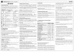
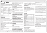
9. MANUAL LEARNING: 'GN6I.a' WIRING DIAGRAM IN CASE OF LOW LOGIC LEVEL COMMUTATION.
14V DC 25A max.
Cut off
circuit
Two-level shock
and tilt sensor
1
Contacts of
Relay K2
The sensor is adjusted
by programming device 'MBPR'
(see device manual)
KSD
Contacts of
Relay K1
12 3
+12 V
123456
Right direction
indicators
1
DOORS (-)
- FN=32, SN=2
+
1 2 3 4 5 6 7 8 9 10
White
Pink
Brown
Black
Orange
Grey
Red
Green
Blue
Yellow
“Alarm” / “Pre-alarm”
“Ground”
+12V
Grey
Yellow
Orange
Black
Yellow
Red
Switches in the door strut,
luggage compartment and / or
bonnet switch
2
Imax=7 A
5
3A
DOORS (+)
FN=32, SN=1
5
2
Ignition switch
4
+12V
ACC
+
-
+12 V
Left direction
indicators
5A
LOCK
4
START
System LED
ON
UNLOCK
3
From central
lock
actuator
+12 V
VD1
R1
3K - 10K
Door lock
contact
for locking
6
Imax=7 A
+12 V for system
6
15A
+12 V for direction
indicators
3
“Ground”
-
+
CONDITION1
Vehicle
battery
VD2
Central lock switch
contact in passenger
compartment
for lockingi
Horn type siren
FN=65, SN=1 - 4
+12 V
Imax=2 A
1
VD3
3A
R2
3K - 10K
Door lock
contact
for unlocking
9
3A
+12V
+12 V
CONDITION2
VD4
Central lock switch
contact in passenger
compartment
for unlocking
+
8
Electronic siren
FN=65, SN=5
SECRET BUTTON
FN=51, SN=1
10. MANUAL LEARNING: 'GN6I.a' WIRING DIAGRAM IN CASE OF HIGH LOGIC LEVEL COMMUTATION.
14V DC 25A max.
Cut-off
circuit
Two-level shock
and tilt sensor
1
Contacts of
Relay K2
The sensor is adjusted
by programming device 'MBPR'
(see device manual)
KSD
Contacts of
Relay K1
12 3
+12 V
123456
Right direction
indicators
1
DOORS (-)
- FN=32, SN=2
+
1 2 3 4 5 6 7 8 9 10
White
Pink
Brown
Black
Orange
Grey
Red
Green
Blue
Yellow
“Alarm” / “Pre-alarm”
“Ground”
+12V
Grey
Yellows
Orange
Black
Yellows
Red
Switches in the door strut,
luggage compartment and / or
bonnet switch
2
5
2
Ignition switch
4
ACC
From central
lock
actuator
UNLOCK
3
LOCKI
4
START
VD1
Door lock
contact
for locking
+
System LED
+12V
ON
Imax=7 A
5
3A
DOORS (+)
FN=32, SN=1
+12 V
6
Central lock switch
contact in passenger
compartment
for locking
Imax=7 A
15A
+12 V for direction
indicators
+
CONDITION1
-
R1
3K - 10K
Door lock
contact
for unlocking
1
Imax=2 A
3A
+
+12V
CONDITION2
9
VD4
R2
3K - 10K
Vehicle
battery
Horn type siren
FN=65, SN=1 - 4
VD3
Central lock switch
contact in passenger
compartment
for unlocking
“Ground”
VD2
+12 V
+12 V
Left direction
indicators
+12 V for system
6
3
+12 V
-
5A
8
SECRET BUTTON
FN=51, SN=1
3A
+12 V
Electronic siren
FN=65, SN=5
+12 V
Note:
Resistors R1, R2 are necessary, if logic levels on on contacts of central lock switch in passenger compartment and door lock is alike in case
the central lock is locked and unlocked. Value is selected for getting enough difference between levels and avoiding to induce disturbances in
electronic systems of vehicle.