1
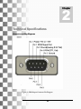
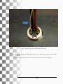
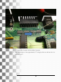
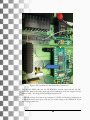
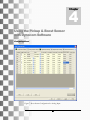
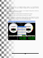
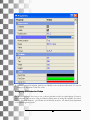
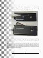
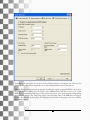
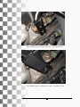
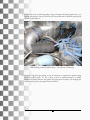
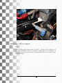
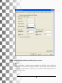
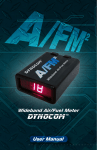
Version 1.0 Copyright © 2012
DC-RPM-iBox User Manual
DYNOCOM SERIES CHASSIS DYNAMOMETERS
DC-RPM-iBox User Manual
Copyright
This manual is copyrighted by Dynocom Industries, Inc., hereafter referred to as Dynocom, and all rights are reserved.
This manual is furnished under license and may only be used or copied in accordance with the terms of such license. This
Manual is furnished for informational use only, is subject to change without notice. Dynocom assumes no responsibility
or liability for any error or inaccuracies that may appear within this document.
Dynocom Industries Inc.
2447 Riverbend West Drive,
Fort Worth • Texas • US
76118
www.dynocom.net
Phone 817.284.8844 • Fax 817.284.8847
Table of Contents
1 ..........................................................2
INTRODUCTION .............................2
DC-AIR LIFT ASSIST
COMPONENTS ..............................2
2 ..........................................................3
INSTALLATION INSTRUCTION ...3
A ............ ERROR! BOOKMARK NOT
DEFINED.
AIR LIFT ASSIST
SPECIFICATIONS .............. ERROR!
BOOKMARK NOT DEFINED.
1
Chapter
Introduction
Congratulations! You have purchased Dynocom’s DC-RPM-iBox electronic RPM gain and filtering for
RPM pickups with built in boost sensor. The system will allow users to use an inductive pickup for
vehicles and motorcycles to pick up the engine RPM signal. Furthermore, the unit is equipped with a
built in boost sensor which outputs a 0-5V signal that is mapped to actual boost/air pressure. The
standard system comes with a 36 PSI gauge pressure sensor; however, an option system is available that
comes with a 100 PSI gauge pressure sensor.
DC-RPM-iBox COMPONENTS
The following is a list of components included within the DC-RPM-iBOX system:
1 x DC-RPM-iBox Electronic Unit
1 x RPM to DC-Controller Interface Cable
1 x Inductive Pickup
DC-RPM-iBox User Manual
2
Chapter
Technical Specifications
Connector and Plug Diagrams
Figure 1 – DB9 Output Connector Pin Diagram
3
Figure 2 – RPM Signal Input Plug Diagram
Analog Output / Boost Sensor
Standard Unit ( 36.3 PSI Max Output ) – MPX4250G
Vmin / Low Voltage: 0.2V = 0 PSI
Vmax/ High Voltage: 4.9 V = 36.3 PSI
High Pressure Unit ( 101.5 PSI Max Output ) – MPX5700G
Vmin / Low Voltage: 0.2V = 0 PSI
Vmax/ High Voltage: 4.7V = 101.5 PSI
4
3
Chapter
DC-Controller Hardware Upgrade
Depending on the version of the DC-Controller, it may be necessary to perform a simple hardware
upgrade to allow the boost to be data logged by the Dynocom hardware & software.
The following tools and components are needed to perform the upgrade:
1) Soldering station with electrical solder
2) Approx. 12” of 28 gauge wire.
3) Small Philips Screwdriver
Step-By-Step Procedure
1) Remove the top cover of the DC-Controller
2) Remove the 8-Pin RPM connector from the DC-Controller board and the front panel.
3) Solder approximately 8” of wire onto the RPM connector PIN 3 as shown in Figure 3.
5
Figure 3. BOOST signal wire to RPM Input Connector
4) Re-install and plug the RPM connector into the front panel and board of the DCController.
5) Solder the free end of the wire from step 3 into the via hole as shown in Figure 4.
6
Figure 4. DC-Controller Via Hole Solder Connection
6) With a second piece of wire, approximately 2.5” in length, solder one end into the via as
shown in Figure 5.
7
Figure 5. DC-Controller Via Hole Short Wire Connection 1
7) Solder the free end of the short wire into the second via shown in Figure 6.
8
Figure 6. DC-Controller Via Hole Short Wire Connection 2
8) Plug the new RPM cable into the DC-RPM-iBox and the other end into the DCController. Scroll to the analog input page of the handheld to verify the voltage in free air,
without boost – the voltage should read approximately 0.24V.
9) Using a short burst of air from an air compressor ( 10 PSI ) and hooking a small piece of
air line to the boost sensor port, verify that you see the voltage on the handheld as well as
the bar gauge on the unit.
9
4
Chapter
Using the Pickup & Boost Sensor
with Dynocom Software
Configuring Boost
Figure 7. Boost Sensor Configuration for Analog Input
10
The boost sensor first has to be configured according to Figure 7 to use with Dynocom’s
dynamometer software. The sensor is designed to integrate with AI3, Analog Input 3, from the
software table shown.
One the Analog Input Dialog box is configured, one can configure the Gauge Screen to add a boost
gauge or label according to the following steps:
1) Open the Gauge View by clicking the Menu bar and selecting View->Gauges.
2) Once the Gauge view is up click the Menu bar and select Layout->Modify.
3) You can either select an existing Label or Gauge, and draw it on the Gauge View, or edit an
existing one. Once a control has been selected, simply right click the control to popup the
properties window and configure it as shown in the following two figures.
11
4) After the control is configured, click Layout->Modify to exit out from modify mode. To save our
changes, it is important to click File->Save.
Configuring RPM Inductive Pickup
The Inductive pickup is not as easy to use, or does it perform as well as an optical pickup. However,
some customers who are use to using an inductive pickup insist on having this capability for various
reasons. In certain situations, good results can be achieved; however, it is almost always dependent
on the vehicles ignition system.
12
Currently, there are two pickups available – Type I is a high gain pickup and works, and Type II is a
low gain pickup. The Type I pickup works on more vehicles and even injectors, but since it has a high
gain inductive coil, it is more difficult to setup. The Type II pickup may not work on injector wires,
due to its low gain coil; however, it is more forgiving to noise in high EMI situations.
For situations where the vehicle may have a wasted spark ignition system, the plug may be fired during
the exhaust stroke, and only at low RPMs – i.e. idle. This may cause issues when calibrating the
sensor. Hence, for most situations, calibrating the sensor at part throttle about 1500 RPM is the
recommended approach.
The best way to set up the inductive probe is to clamp it on either a plug wire or coil wire. In
situations where the vehicle has coil over plug packs, you would select “Plugs” in the software for the
RPM pickup type. To configure the default pickup type to calibrate it for the particular vehicle, it is
best to use a trial and error approach and enter the engine RPM settings via selecting Setup->Default
Engine Settings from the menu bar as shown:
13
Furthermore, in some cases one can also use the inductive pickup on an injector wire. However, the
injector power cable must be separated so as to only clamp around one wire of the injector.
After the dialog is configured, and an operator is holding the engine at a specified RPM, one can view
the gauge screen by clicking the GO button on the handheld, and CANCEL to close it out. If the
RPM does not match the tachometer of the car, the user has to open up the Engine Settings dialog
box to modify settings. The “Plug Firing Angle” is the most likely cause of an RPM that is too high or
too low. By changing the firing angle and jumping back and forth to the gauge view, one can dial in
the settings correctly.
14
Once the settings for the particular vehicle or ignition system is complete, one can begin to use the
RPM Inductive pickup as a pickup source and perform dyno runs as with any other type of sensor.
Note: Ignition systems are very noisy are automobiles, and coil-over-plug & coil packs have
voltage spikes that tend to cause the RPM readings to widely fluctuate and spike. There are
several tricks that one can use depending on the particular inductive pickup one has.
Troubleshooting
RPM reading is erratic and jumps around.
Solution:
Move the RPM pickup to another coil or plug as well as ground the vehicle to the dyno by
using battery jumper cables – so as the frame of the vehicle contacts earth (any metal point
on the dynamometer).
Attenuate the RPM pickup probe by the following different methods.
a) If the clamp is over only one of the two wires going to the coil source wires, have the
clamp over both the coil wires – this helps drop the signal to the pickup and assists in
providing a clean pulse.
b) It is possible to move from a coil/plug wire to an injector wire as shown. Depending
on the signal, it may be necessary to clamp over all the wires to the injector, or break
open the loom and clamp only over one as shown.
15
Type I RPM Clamp over Injector wire set – Ford 2008 GT500
Type II RPM Clamp over Injector wire split – Ford 2008 GT500
16
c) If the clamp is on an actual large plug or large coil output wire (8mm ignition wire ), try
moving the pickup as far away from the coil as possible and/or shield the pickup with
a piece of insulated hose
EMI Shielding around the RPM Clamp – 900 HP 5.0L ’94 Mustang
.
d) If using a high gain type pickup, it may be necessary to attenuate the signal coming
from the ignition pulse. To do so, place a piece of cardboard, plastic, or rubber
between the clamp and have the ignition wire going thru the clamp. By changing the
thickness of the spacer, the signal can be reduced.2.
17
RPM reading is stable but too high/low
Solution:
Change the firing angle settings within the software. Typically, most V8 engines use a
firing angle of 720 degrees, and most 4 cylinders use a firing angle of 120 or 180 degrees. If
the ignition system is a wasted spark type, the firing angle may have to be reduced to get a
lower RPM reading.
18
RPM reading on handheld differs than RPM reading in software.
Solution:
This is most likely a conflict between using Mode I and Mode II of operation see
Introduction to Chassis Dyno Operation manual or DC-Controller Mode I Operation
manual. To configure Mode I of operation, you must do this within the Setup screens of
the controller as shown.
19
20
21
22