1
RF100 Series
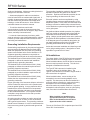
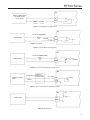
DO
INDUCTION LOAD (SOLENOID OR
RELAY) USING A SNUBER DIODE
IS HIGHLY RECOMMENDED
DO#
EXTERNAL POWER
CONTROL
DCOM
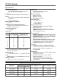
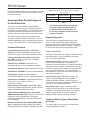
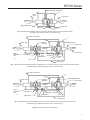
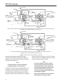
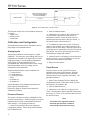
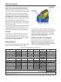
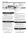
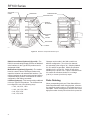
Figure 9. Solid State Relays - Discrete Output
The Discrete Output on the I/O termination board can
be used in:
• Toggle mode
• Latching mode
• Timed mode
Calibration and Configuration
All field/process inputs must be calibrated to the full
range input of the installed sensors.
Analog Inputs
Analog Input calibration routines support a 2-point
calibration. The low-end or zero reading (Set Zero) is
calibrated first, followed by the high-end or full-scale
reading (Set Span). The calculated and diagnostic
analog inputs, such as instantaneous flow,
accumulated flow, barometric pressure, input voltage,
Board temperature, and Logic voltage, are not
designed to be field calibrated.
Supported inputs with the 2-point calibration are:
• P1 Inlet pressure
• P2 Outlet pressure
• P3 Auxiliary pressure
• Travel
• I/O Board AI1
• I/O Board AI2
A brief description of the calibration procedure for
these inputs is described below.
Refer to the RegLink Software User Manual for
additional information.
Pressure Sensors
The pressure sensors are factory calibrated for their
full scale rated pressure. Routines support a two point
calibration at zero (open to atmosphere) and at full
scale pressure. The general procedure is:
1. Select Tools>Configure Device to display the
Configuration window. Select the AI point and select
the AI Calibration tab.
18
2. Click the calibrate button.
3. Calibrate the zero value for the pressure input.
This can be done by referencing the sensor to
atmospheric pressure. Enter the tester value (in
engineering units) and click the Set Zero button. In
this case the tester value would be “0”.
4. To calibrate the span value (100% of full scale
range) for the pressure input, apply pressure to the
sensor for the full scale range. Enter the Tester Value
(actual pressure in engineering units) and click the Set
Span button. Be sure to allow enough time for the
Live Reading to update and stabilize.
5. Confirm that the Live Reading is correct and click
Accept or Cancel. If the Live Reading is not correct,
select cancel and repeat the procedure.
6. Repeat for each sensor.
Travel Sensor
The travel sensor on the Type RF100 must be
calibrated to the travel of the regulator. Routines
support a two point calibration at zero (regulator
closed) and at full scale (regulator wide open). The
general procedure is:
1. Select Tools>Configure Device to display the
Configuration window. Select the AI point for travel
and select the AI Calibration tab.
2. Click the Calibrate button.
3. Calibrate the zero value (0% of range) for the
Travel. This should be with the regulator pressurized
and in lock up. Enter “0” for the tester value and click
the Set Zero button.
Note
Full stroke of the regulator must be
achieved and should be verified to
insure RegFlo instrument accuracy.