1
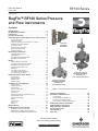
RF100 Series
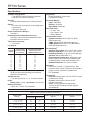
Specifications
Available Configurations
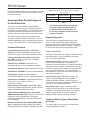
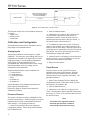
• Type RF100 Flow and Pressure Instrument
• Type RF110 Pressure Instrument
Security
15 users with passwords and 3 levels of access
Alarms
• Hi, Hi/Hi, Low, and Low/Low on all analog inputs
• Logic alarms
• 240 logs in alarm log
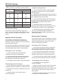
Sensor and Pressure Ranges(1)
See table 1
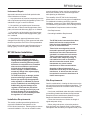
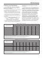
Instantaneous Flow Estimation Accuracy
See tables 2 and 3 and the Instantaneous Flow
Estimation Accuracy section.
Travel Sensor Accuracy
± 1 % of span
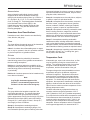
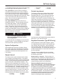
Log Interval
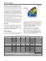
LOG
INTERVAL,
MINUTES
STANDARD HISTORY
CAPACITY, DAYS
(840 LOGS STORED,
ALL VERSIONS)
EXTENDED HISTORY CAPACITY,
DAYS (8640 LOGS STORED,
AVAILABLE ONLY FOR
FIRMWARE VERSION 2.xx)
1
2
3
4
5
6
10
12
15
20
30
60
0.6
1.2
1.8
2.3
2.9
3.5
5.8
7.0
8.8
11.7
17.5
35.0
6
12
18
24
30
36
60
72
90
120
180
360
Daily Log
35 days of daily values (average, accumulated,
minimum and maximum)
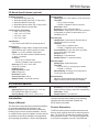
Sample Intervals
1, 10, and 30 seconds; 1, 2, 5, 10, and 30 minutes
Power
Battery Input: 3.6 Vdc; Input Power: 10 to 28 Vdc
Battery Information
Lithium Ion, 3.6 Vdc, 19.0 amp-hours
Diagnostics
Board Temperature, Power Input,
Logic/Battery Voltage
Processor Memory
Flash: 128 Kbytes
EEProm: 32 Kbytes
Static RAM: 128 Kbytes
Real Time Clock
• Hr : Min : Sec
• Day : Month : Year
• Battery Backed
Communication Ports
Operator Interface: RS-232 (RX, TX, RTS);
ROC protocol only
COM1: RS-485; ROC and Modbus protocol
COM2 (Optional): RS-232 or V-22 BIS Modem;
ROC and Modbus protocol
Environmental(1)
Operating Temperature: -40° to 167°F (-40° to 75°C)
Storage Temperature: -58° to 185°F (-50° to 85°C)
Operating Humidity: 5% to 95% non-condensing
Vibration: Meets SAMA PMC 31.1
Electromagnetic Interference: Designed to meet
requirements of IEC 61326 Electrical Equipment
for Measurement, Control, and Laboratory Use
Radiated Emissions: FCC Part 15 Class A
Approvals
CSA Class I, Division 1, Explosion-Proof, Gas
Groups C and D; Class I, Division 2, Nonincendive
groups C and D; Certified to Canadian and
U.S. Standards
Connections
Electrical: Housing has 2 1/2-inch 14 NPT conduit
connections for wiring
Process: Sensors have 1/4-inch 18 NPT
process connections
Vents: Vent connections are tapped with
1/4-inch 18 NPT threads for use with piping in
pit installations
1. The pressure/temperature limits in this manual and any applicable standard or code limitation should not be exceeded.
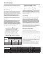
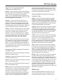
Table 1. Sensor and Pressure Ratings, and Accuracy
SENSOR RANGE,
PSIG (bar)
MAXIMUM OPERATING PRESSURE,
PSIG (bar)
MAXIMUM EMERGENCY PRESSURE,
PSIG (bar)
2.5
1.0
1.0
9 (0,62)
45 (3,10)
85 (5,86)
300 (20,7)
475 (32,8)
475 (32,8)
0.5
0.5
1.0
1.0
185 (12,8)
585 (40,3)
475 (32,8)
1500 (103)
0 to 500 (0 to 34,5)
0 to 1000 (0 to 68,9)
0.5
0.5
1.0
1.0
985 (67,9)
1500 (103)
1500 (103)
1500 (103)
0 to 1500 (0 to 103)
0.5
1.0
1500 (103)
1500 (103)
-40° to 167°F
(-40° to 75°C)
1.5
0.5
0.5
0 to 100 (0 to 6,90)
0 to 300 (0 to 20,7)
0 to 30-inches w.c. (0 to 75 mbar)
0 to 15 (0 to 1,03)
0 to 35 (0 to 2,41)
2
ACCURACY, % OF SPAN
-4° to 122°F
(-20° to 50°C)