1
Engineered Bus Door Systems
CLASS Diagnostic Software
User Manual Revision AL
Release Date: 04/15/2010
For CLASS v3.34 and Voice Annunciator v0.47
© 2003-2010 Vapor Bus International
CLASS Diagnostic Software
© 2003-2010 Vapor Bus International
U.S. Patents are applicable and/or pending to products described and illustrated herein.
Vapor reserves the right to discontinue products or change product specifications or designs at any time without
notification.
All rights reserved. No parts of this work may be reproduced in any form or by any means - graphic, electronic, or
mechanical, including photocopying, recording, taping, or information storage and retrieval systems - without the
written permission of the publisher.
Products that are referred to in this document may be either trademarks and/or registered trademarks of the
respective owners. The publisher and the author make no claim to these trademarks.
While every precaution has been taken in the preparation of this document, the publisher and the author assume no
responsibility for errors or omissions, or for damages resulting from the use of information contained in this
document or from the use of programs and source code that may accompany it. In no event shall the publisher and
the author be liable for any loss of profit or any other commercial damage caused or alleged to have been caused
directly or indirectly by this document.
1010 Johnson Drive
Buffalo Grove, Illinois 60089 USA
Phone: 847.777.6400
Fax: 847.520.2222
Internet: www.vapordoors.com
Contents
I
Table of Contents
Part I Definitions
1
Part II Product ID
2
Part III Toolbar Buttons
4
Part IV Controls Window
5
Part V CLASS 3 (50330055)
6
1 Step-By-Step
...................................................................................................................................
Setup
6
2 Parameters
...................................................................................................................................
Window
10
Allow able Range
.......................................................................................................................................................... 10
Targets
.......................................................................................................................................................... 11
General Notes
......................................................................................................................................................... 11
LPS
......................................................................................................................................................... 11
Panel Limit ......................................................................................................................................................... 12
MSU
......................................................................................................................................................... 12
MSU Detection
.........................................................................................................................................................
Limit
12
RPS
......................................................................................................................................................... 12
Programmed
.........................................................................................................................................................
Target Values
13
Modes
.......................................................................................................................................................... 13
TempComp.........................................................................................................................................................
Mode
13
Snow Mode
......................................................................................................................................................... 13
Relay Mode......................................................................................................................................................... 13
Periodic Report
......................................................................................................................................................... 14
Target Reporting
......................................................................................................................................................... 14
1S Mode ......................................................................................................................................................... 14
No 5° Open......................................................................................................................................................... 14
Long MSU Ignore
......................................................................................................................................................... 15
MSU Target.........................................................................................................................................................
Reduction
15
MSU TTO Mode
......................................................................................................................................................... 15
No Floor TTO
......................................................................................................................................................... 16
No Floor DFO
.........................................................................................................................................................
Mode
16
No Floor Closing
.........................................................................................................................................................
Mode
17
Drunk Alarm
......................................................................................................................................................... 18
High Drunk.........................................................................................................................................................
Alarm Out
18
5° Enables .........................................................................................................................................................
CLASS
19
Panel Target
.........................................................................................................................................................
Reduction
19
Unfiltered Mode
......................................................................................................................................................... 19
Voltage (volts)/
..........................................................................................................................................................
Tim ers (seconds)
20
Units and Setting
.........................................................................................................................................................
Values
20
VREF Normal
......................................................................................................................................................... 20
VREF Calibration
......................................................................................................................................................... 20
Hold Open .........................................................................................................................................................
Timer 1 (Relay Mode)
20
Hold Active.........................................................................................................................................................
Timer 2 (5°)
21
Open Limit .........................................................................................................................................................
Timer 3 (Snow Mode)
21
© 2003-2010 Vapor Bus International
I
II
CLASS Diagnostic Software
Door Recycle
.........................................................................................................................................................
Limit (Snow Mode)
21
Open Request
.........................................................................................................................................................
ON Time
22
Open Request
.........................................................................................................................................................
OFF Time
22
Controller
.......................................................................................................................................................... 23
Get from RAM
......................................................................................................................................................... 23
Save to EEPROM
......................................................................................................................................................... 23
Reset Controller
......................................................................................................................................................... 23
PC
.......................................................................................................................................................... 24
Load Default
.........................................................................................................................................................
File
24
Quick Save.........................................................................................................................................................
File
24
Load from File
......................................................................................................................................................... 24
Save to File......................................................................................................................................................... 24
Verify from.........................................................................................................................................................
File
25
3 Advanced
...................................................................................................................................
Parameters
26
Modes
.......................................................................................................................................................... 26
MSU 5° Pullup
.........................................................................................................................................................
Mode
27
Panel 85° Pullup
.........................................................................................................................................................
Mode
27
DA Pullup/Move
.........................................................................................................................................................
Floor
27
Auto Reset.........................................................................................................................................................
Timer Mode
28
No Opening.........................................................................................................................................................
Req Mode
28
Fault Holds.........................................................................................................................................................
Door Open
28
No DFO Open
.........................................................................................................................................................
Req
28
TTO Sensitivity
.........................................................................................................................................................
Mode
29
DFO Sensitivity
.........................................................................................................................................................
Mode
29
Long TTO Mode
......................................................................................................................................................... 29
Long DFO Mode
......................................................................................................................................................... 30
No HoldOpen
.........................................................................................................................................................
Mode
30
Anti-Flap Mode
......................................................................................................................................................... 30
Medium Noise
.........................................................................................................................................................
Mode
30
Invert Status
.........................................................................................................................................................
Output
31
Mockup Mode
......................................................................................................................................................... 31
DA-I used for
.........................................................................................................................................................
TTO
31
PushButton.........................................................................................................................................................
Invert
31
Cushion Valve
.........................................................................................................................................................
On Close
32
MSU Ringdow
.........................................................................................................................................................
n Mode
32
High Noise .........................................................................................................................................................
Mode
32
Easy Floor .........................................................................................................................................................
Mode
33
DA Alw ays.........................................................................................................................................................
Enabled
33
Easy NoFloor
.........................................................................................................................................................
Mode
33
Delay Boot.........................................................................................................................................................
Mode
33
No 5° Delays
.........................................................................................................................................................
Boot
34
DA Continuous
.........................................................................................................................................................
Mode
34
K2 Enabled.........................................................................................................................................................
Mode
34
Voice Annunciator
.........................................................................................................................................................
Mode
34
MSU DFO Table
.........................................................................................................................................................
Mode
35
DA NoFloor.........................................................................................................................................................
Mode
35
Extend Floor
.........................................................................................................................................................
Detection
35
Easy TTO Mode
......................................................................................................................................................... 36
Status On Sensors
......................................................................................................................................................... 36
DA VREF Mode
......................................................................................................................................................... 36
MSU Timeout
.........................................................................................................................................................
Mode
36
Controller
.......................................................................................................................................................... 36
Save to EEPROM
......................................................................................................................................................... 36
Reset Controller
......................................................................................................................................................... 37
© 2003-2010 Vapor Bus International
Contents
PC
III
.......................................................................................................................................................... 37
Load Default
.........................................................................................................................................................
File
37
Load From.........................................................................................................................................................
File
38
Verify From
.........................................................................................................................................................
File
38
Save to File......................................................................................................................................................... 39
4 Self-Profiling
...................................................................................................................................
Mode
40
Target Size Exam
..........................................................................................................................................................
ple
41
5 Scope...................................................................................................................................
Setup
43
Scope Setup Window
.......................................................................................................................................................... 43
Enter/Exit Test..........................................................................................................................................................
Mode
43
Mode
.......................................................................................................................................................... 43
Sensor On/Off..........................................................................................................................................................
Buttons - General
43
LPS On/Off .......................................................................................................................................................... 43
MSU On/Off .......................................................................................................................................................... 43
RPS On/Off .......................................................................................................................................................... 43
LPS Send
.......................................................................................................................................................... 44
MSU Send
.......................................................................................................................................................... 44
RPS Send
.......................................................................................................................................................... 44
6 Inputs/Outputs
................................................................................................................................... 44
Inputs/Outputs
..........................................................................................................................................................
Window
44
Inputs
.......................................................................................................................................................... 44
Relays
.......................................................................................................................................................... 44
Outputs
.......................................................................................................................................................... 45
LEDs
.......................................................................................................................................................... 45
Door State
.......................................................................................................................................................... 45
7 Built In
...................................................................................................................................
Tests (BIT)
46
BIT Window .......................................................................................................................................................... 46
Built In Tests ..........................................................................................................................................................
(BIT)
46
Reset
.......................................................................................................................................................... 47
8 EEPROM
...................................................................................................................................
Status
47
EEPROM Status
..........................................................................................................................................................
Window
47
EEPROM Status
.......................................................................................................................................................... 47
9 Controller
...................................................................................................................................
Programming
48
Controller Program
..........................................................................................................................................................
m ing Window
48
Reset Controller
.......................................................................................................................................................... 48
Program m ing..........................................................................................................................................................
Mode
48
Exiting Program
..........................................................................................................................................................
m ing Mode
48
Stuck in Programming
.........................................................................................................................................................
Mode
50
10 Text &...................................................................................................................................
Target Log
53
Text & Target ..........................................................................................................................................................
Log Window
53
General Usage.......................................................................................................................................................... 53
Sensor
.......................................................................................................................................................... 54
Target Distance
.......................................................................................................................................................... 54
Message
.......................................................................................................................................................... 54
11 Serial...................................................................................................................................
Port Setup
54
Setup
.......................................................................................................................................................... 54
12 Data Monitor
................................................................................................................................... 55
Data Monitor Window
.......................................................................................................................................................... 55
Capabilities .......................................................................................................................................................... 55
13 Test Door
...................................................................................................................................
Operation
56
© 2003-2010 Vapor Bus International
III
IV
CLASS Diagnostic Software
Test Door Operation
..........................................................................................................................................................
Window
56
14 PC & Timers
................................................................................................................................... 57
Save to EEPROM
.......................................................................................................................................................... 57
Load from File.......................................................................................................................................................... 57
Verify from File
.......................................................................................................................................................... 58
Reset Controller
.......................................................................................................................................................... 58
Load Default File
.......................................................................................................................................................... 58
Save to File .......................................................................................................................................................... 59
15 Voice ...................................................................................................................................
Annunciator Parameters
60
Enable Message
.......................................................................................................................................................... 61
Modes
.......................................................................................................................................................... 61
Part VI Voice Annunciator
63
1 Connection
................................................................................................................................... 63
2 VA - User
...................................................................................................................................
Interface
65
VA - Setup for..........................................................................................................................................................
CLASS
66
VA - Setup for..........................................................................................................................................................
Stand-Alone
68
VA - Setup for..........................................................................................................................................................
PLC Encoding
70
3 VA - Message
...................................................................................................................................
Play & Download
72
4 VA - Wiring
................................................................................................................................... 73
Part VII CLASS 2 (50130193)
74
1 General
...................................................................................................................................
Notes
74
2 Parameters
...................................................................................................................................
Window
75
3 Changing
...................................................................................................................................
Parameters
75
4 LPS ................................................................................................................................... 76
5 Panel ...................................................................................................................................
Limit
76
6 MSU ................................................................................................................................... 76
7 MSU Limit
................................................................................................................................... 76
8 RPS ................................................................................................................................... 77
9 VREF Normal
................................................................................................................................... 77
10 VREF Calibration
................................................................................................................................... 77
11 Hold Open
...................................................................................................................................
Timer 1
77
12 Hold Active
...................................................................................................................................
Timer 2
78
13 Door Recycle
...................................................................................................................................
Limit
78
14 Open Limit
...................................................................................................................................
Timer 3
78
15 BIT
................................................................................................................................... 78
16 Relay ...................................................................................................................................
Mode
79
17 NPN Mode
................................................................................................................................... 79
18 1S Mode
................................................................................................................................... 79
19 MSU TTO
...................................................................................................................................
Mode
79
20 MSU Target
...................................................................................................................................
Reduction
80
21 Low Enable
...................................................................................................................................
In
80
© 2003-2010 Vapor Bus International
Contents
V
22 High Drunk
...................................................................................................................................
Alarm Out
80
23 Drunk ...................................................................................................................................
Alarm Panels
80
24 Drunk ...................................................................................................................................
Alarm MSU
80
25 No 5° Open
................................................................................................................................... 81
26 TempComp
...................................................................................................................................
Mode
81
27 Snow ...................................................................................................................................
Mode
81
28 Periodic
...................................................................................................................................
Report
81
PeriodicReport
..........................................................................................................................................................
Definition
82
29 Target...................................................................................................................................
Reporting
83
30 Test Mode
................................................................................................................................... 84
31 Normal
...................................................................................................................................
Mode
84
32 Upload
...................................................................................................................................
to Controller
85
33 Reset ...................................................................................................................................
Controller
85
34 Reset ...................................................................................................................................
Status
85
35 Panel ...................................................................................................................................
Target Reduction
86
36 5° Enables
...................................................................................................................................
CLASS
86
37 Unfiltered
...................................................................................................................................
Mode
86
38 FirmwareVersion
................................................................................................................................... 87
39 Load From
...................................................................................................................................
File
87
40 Save To
...................................................................................................................................
File
87
41 Load Default
................................................................................................................................... 87
42 Quick ...................................................................................................................................
Save
87
43 LPS On
...................................................................................................................................
Off
88
44 RPS On
...................................................................................................................................
Off
88
45 MSU On
...................................................................................................................................
Off
88
46 Pulse ...................................................................................................................................
Mode
88
47 No Floor
...................................................................................................................................
Mode - Full
89
48 No Floor
...................................................................................................................................
Mode - MSU
90
49 Reminder
................................................................................................................................... 91
50 Text &...................................................................................................................................
Target Log
91
Text & Target ..........................................................................................................................................................
Log Window
91
General Usage.......................................................................................................................................................... 92
Sensor
.......................................................................................................................................................... 92
Message
.......................................................................................................................................................... 92
Part VIII Reference - CLASS Wiring
93
1 Sensor...................................................................................................................................
Wiring
93
2 CLASS...................................................................................................................................
2 Main Connector (P1)
94
3 CLASS...................................................................................................................................
3 Main Connector (P1)
95
CLASS 3 Input
..........................................................................................................................................................
Wiring
96
4 Switch...................................................................................................................................
Connections
97
© 2003-2010 Vapor Bus International
V
VI
CLASS Diagnostic Software
Type 14
Type 22
Type CZ
.......................................................................................................................................................... 97
.......................................................................................................................................................... 97
.......................................................................................................................................................... 98
5 RJ45 to
...................................................................................................................................
DB9F Adapter Wiring - CLASS
99
6 RJ45 ...................................................................................................................................
to DB9F Adapter Wiring - VA
100
Part IX Revisions
101
© 2003-2010 Vapor Bus International
Definitions
1
1
Definitions
DFO (Door Fully Open) is determined by activation of a switch or sensor when the
door reaches the fully open position.
The Drunk Alarm mode is activated by a specific input (IN2 or /IN2).
When activated, if the door is both fully closed and is not enabled, the
appropriate sensors will be activated for short bursts at recurring intervals.
Any targets seen at those times will be annunciated by means of a specific
output (OUT2 MSU for CLASS 2, /DA-O for CLASS 3)
The Drunk Alarm Mode activation will be temporarily ignored any time the door
is not fully closed or is enabled - during that time normal operation of the sensors
will take place.
The MSU is the Middle Sensor Unit.
TARGET: An object detected by CLASS' sensing system.
Fixed Target: a Target that is part of CLASS' "fixed" environment, i.e., always
present. Fixed Targets may be permanently programmed by the installer or may
be automatically determined by CLASS at turn-on
Acquired Target: a Target that is not "fixed"; typically a passenger.
TTO (Touch To Open) is an operational state of the CLASS controller. In the TTO
state, the door has been unlocked or authorized (typically the Green Light is on) and
CLASS is waiting for a target detection (or a signal from 5 degree switch that the door
has been pushed open beyond its activation point). Upon either of those events,
CLASS will issue a Door Open Request.
See No 5° Open 14 for an exception to the above.
Normally, Panel Sensors are active in the TTO state; the MSU may also be activated
depending on MSU TTO Mode 15
The Status Light will be turned on when CLASS detects an error condition. (Note
CLASS will continue to function.)
© 2003-2010 Vapor Bus International
2
2
CLASS Diagnostic Software
Product ID
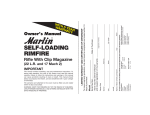
Connected to CLASS 2 Controller:
To initiate communication: Press the CLASS 2 Mode Button
Connected to CLASS 3 Controller:
To initiate communication: If the Cancel/OK button says "OK",
press it to continue. Otherwise, press the CLASS 3 Mode Button
© 2003-2010 Vapor Bus International
Product ID
3
Connected to Voice Annunciator:
To initiate communication: If the Cancel/OK button says "OK",
press it to continue. Otherwise, press the Voice Annunciator Mode Button
If, instead of connecting, the warning message is seen, it indicates that there is
something in the computer running the CLASS Diagnostic that is preventing access to
the COM (serial) port. This is usually caused by some other software program (such as
a PDA or Blackberry interface) having "grabbed" the COM port. It is NOT a problem
with the CLASS Diagnostic, and must be rectified by the user before the CLASS
Diagnostic program can be used. Typically this is solved by closing the program using
the port and restarting the CLASS Diagnostic.
© 2003-2010 Vapor Bus International
4
3
CLASS Diagnostic Software
Toolbar Buttons
* indicates button is only applicable to Voice Annunciator
© 2003-2010 Vapor Bus International
Toolbar Buttons
4
5
Controls Window
The diagnostic's various "windows", such as Parameters, Scope Setup, etc., are known
as controls
To select any control, use the Menu Bar to select either:
File
New
or
Window New Window
Then double-click on the desired control.
Or use the associated Toolbar Buttons
© 2003-2010 Vapor Bus International
4
.
6
CLASS Diagnostic Software
5
CLASS 3 (50330055)
5.1
Step-By-Step Setup
New CLASS 3 Controller Installation – Step-by-Step Basic Setup
Assumptions
These instructions explain the basic steps to follow when configuring a CLASS controller for
a specific environment.
These instructions apply to typical buses – LRVs may require a different approach (not
covered in this document.)
CLASS Controller and sensors are fully installed and correctly wired.
Bus PLC is correctly programmed
Bus is fully operational
Laptop with CLASS Diagnostic and Oscilloscope are correctly connected.
These instructions cover performance-related settings. Customer preferences, such as Drunk
Alarm settings, Driver-Controlled operation, etc, must be ascertained and programmed
separately.
Note: make sure that the door is closed and clear of any non-fixed targets any time
that CLASS is turned on or Reset
(i.e., stand out of the way).
BASIC SETUP
1. Turn CLASS off.
2. Measure & record the distance in centimeters from each sensor face to the floor.
3. Make sure the door is closed and clear
4. Turn CLASS on.
5. Run CLASS Diagnostic.
6. Insert the distances measured in Step 2 into the appropriate left-most target table boxes (see
below)
Target Table
7. Clear out all the other values in the target tables (set to '0')
8. Verify that VREF Normal is set to 2.00 and VREF Calibration is set to 0.50 (see below)
© 2003-2010 Vapor Bus International
CLASS 3 (50330055)
9. Click on
to upload the revised table
10. Click on
to reset and re-learn targets.
7
11. Examine the target table for any new “learned” targets (other than the floor). For each target,
determine the physical cause.
One method of determining the physical cause is by use of the oscilloscope connected to the
appropriate sensor. While observing the scope, use a movable target (a hand, an extended
tape measure, etc.). Move the target closer to or further away from the sensor until the
target’s echo coincides or overlaps the echo being investigated. The moving target will then
be at the same position as the target being investigated.
A second method is to use the scope to display the distance to the target being investigated
(refer to the CLASS Oscilloscope Setup User Manual for setup) and then use the tape
measure to find whatever is at that distance from the sensor.
One the physical cause is determined, measure the actual distance, and insert the measured
distance in the target table in place of the “learned” value.
Note: the actual distance should be used in place of the “learned” distance because the learned
distance is based on an assumption of the speed of sound based on room temperature.
Depending on actual air temperature, the actual distance may be somewhat different than the
learned distance; using the actual distance will allow the full built-in tolerance range to be
used.
Reminder: Always make sure to clear (set to '0') any values that you do NOT want
programmed before clicking
12. Click on
to upload the revised table.
13. Click on
to reset and re-learn targets.
14. Test the door operation.
a. Verify that when enabled, the door does not open until a valid target (hand) is sensed.
b. Verify that the door will close and does not ‘flap’ (re-open one or more times while
attempting to close).
c. Repeat 14.a and 14.b several times.
© 2003-2010 Vapor Bus International
8
CLASS Diagnostic Software
15. Using the oscilloscope, monitor each sensor. (Use Persistence if appropriate. This will allow
the scope traces to build up over time so that higher-amplitude echoes that only occur
sporadically may be seen.) For each sensor:
a. Look for any echo either close to or greater than 0.5V. For any such echo, determine its
physical cause and its distance from the sensor, and verify that it is already in the target
table. If not in the table, decide if it should be in the table by observing its maximum
amplitude over a few minutes’ time (by using Persistance) and by assessing the ambient
air temperature. (If the air temperature is warm, the amplitude will likely be higher when
the temperature is colder.) If the echo is not significantly greater than 0.5V and the air is
cool, it is safer to omit the target. Otherwise, add it in. If the VREF Normal will be
reduced below 2.00V for greater sensitivity, it will be more risky to omit targets.
b. For all sensors, but especially for the MSU, perform step 15.a over the full range of
door movement by dumping the air and slowly moving the door while observing the
oscilloscope.
16. Set the MSU Detection Limit as follows:
a. The goal of using MSU Detection Limit is to reduce the number of fixed targets in the
MSU table.
b. Since:
i. targets detected while the door is opening do not matter (the door is already in the
process of opening so a further door-open request is superfluous)
ii. the MSU is typically not turned on until the door reaches fully open
iii. targets on the doors such as brush covers are typically not seen when the door is
fully open
iv. But: these targets will be seen at turn-on calibration (doors are closed) and added to
the MSU target table, thus causing unnecessary dead-zones.
So: note or measure the distance to the closest target (smallest distance) which is not visible at
door fully open and then set the MSU Detection Limit to 94% of that distance (distance x
0.94). (See Target Table figure above)
c. If the targets are seen at door fully open, set the MSU Detection Limit equal to the
MSU floor value. This will maximize CLASS coverage.
17. Assuming that targets can not be seen at door fully open, click on
to turn it on.
Then, once MSU Target Reduction is enabled, any MSU targets at distances beyond the
MSU Detection Limit (but not including the floor) which can not be seen when the door is
fully open may be removed from the target table.
Caution If MSU TTO Mode is turned on, the MSU will be ON at door fully closed down
: to 110 cm. (condition 16.b.ii will no longer be true) so if the MSU Detection
Limit is set at less than 110 cm, any targets between the detection limit and 110
cm will be seen.and therefore must be left in the table. If the MSU Detection
© 2003-2010 Vapor Bus International
CLASS 3 (50330055)
9
Limit is greater than 110 cm, then MSU TTO Mode is fully compatible.
18. No Floor Mode: Turn on No Floor DFO - MSU and No Floor Closing - MSU.
Make sure to verify that the MSU receives a strong floor signal at all times if these modes
are used (this typically requires using an oscilloscope).
19. No 5° Open: The standard setting for No 5° Open is ENABLED. At the very least, it
should be ENABLED for standard Slide-Glide doors, or any doors not having a positive
locking mechanism. (If No 5° Open is not enabled, when the door is authorized and pushed
in a manner to move past the 5° point without being detected by a CLASS sensor, the
controller will issue a door-open request.)
20. Make sure that unless Relay Mode is being used, Hold Open Timer 1 is set to be less than
Open Request On Time. (Typically, Open Request On Time is set to 0.3, and Hold Open
Timer 1 is set to 0.1.)
21. Click on
to upload the revised table
22. Click on
to reset and re-learn targets. Observe whether new (unprogrammed) targets have been learned and, if so, why. Then re-configure accordingly.
23. Fully test the settings by operating the door and observing its operation.
24. Save your configuration by using
with an appropriate filename (typically
includes builder, transit authority and bus number, such as NFI-CTA-Bus 999)
References
CLASS Diagnostic Software User Manual (Help file, online or PDF)
CLASS Oscilloscope Setup User Manual (Help file, online or PDF)
CLASS Theory of Operation (TB08-05-096)
CLASS Installation and Setup (TB08-03-192)
© 2003-2010 Vapor Bus International
10
5.2
CLASS Diagnostic Software
Parameters Window
NOTE:
Modes may be changed at any time.
The new values will take effect immediately, but will remain in effect only until the next
Reset Controller 23 if not saved.
Changes to Voltage/Timers will not take effect until saved.
Changes to Targets will not take effect until saved and reset.
To permanently save changed parameters, click Save to EEPROM
Reset Controller 23 .
5.2.1
23
. To reset, click
Allowable Range
Parameter
Min
Default
Max
Unit
LPS,MSU
MSU
MSU Detection Limit
VREF Normal
30
30
60
0.29
85,187
199
90
2.00
255
255
[MSU Floor]
5.00
cm
cm
cm
V
© 2003-2010 Vapor Bus International
CLASS 3 (50330055)
VREF Calibration
Hold Open Timer 1 (Relay Mode)
Hold Active Timer 2 (5º)
Open Limit Timer 3 (Snow Mode)
Open Request ON Time
Open Request OFF Time
Door Recycle Limit (Snow Mode)
See EEPROM Status
5.2.2
Targets
5.2.2.1
General Notes
47
0.29
0.1
0.01
4.00
0.01
0.00
3
0.50
1.00
1.00
4.00
0.30
0.00
3
5.00
10.0
10.00
20.00
1.00
2.00
10
11
V
sec
sec
sec
sec
sec
#
for more information.
A target is entered as a distance (in centimeters) from the face of the sensor to the
fixed object.
The first (left-most) box MUST contain the distance to the floor.
If TempComp Mode 13 is enabled, the second box MUST contain the distance to
the cooperative object. (This applies only to LPS & RPS.)
The next boxes contain any other fixed objects (e.g., brushes, handles, window
ledges, etc.)
Boxes MUST NOT be left empty - if no fixed target exists for a given box, a '0' must
be entered.
A zero ('0') is not allowed between any non-zero fixed targets; all zeros must be to
the right. (The first zero encountered stops the reading of further target boxes for the
specific sensor.)
Fixed target values will also appear in the boxes at CLASS™ turn-on as a result of
the turn-on calibration. The values seen will therefore be a combination of any values
previously programmed and those detected at turn-on. (To determine which targets
are programmed and which are detected at turn-on, refer to Programmed Target
Values 13 .)
5.2.2.2
LPS
The boxes under LPS (Left Panel Sensor) are to enter/display fixed targets
the LPS.
Range:
Min = 30
© 2003-2010 Vapor Bus International
Default = 85, 187
Max = 255
1
seen by
12
CLASS Diagnostic Software
See Parameters Window 10 for control location.
5.2.2.3
Panel Limit
Panel Limit: The maximum distance from the Panel sensors (in centimeters) at which
the Panel sensors will detect a target while the door is nearly closed (5º switch is
active), if Panel Target Reduction 19 Mode is enabled. This is used to prevent the
Panels from "seeing" extra targets while the doors are closed.
Range:
Min = 30
(whichever is smaller)]
Default = 110
Max = [LPS or RPS Floor value
See Parameters Window 10 for control location
5.2.2.4
MSU
The boxes under MSU (Middle Sensor Unit) are to enter/display fixed targets
the MSU.
Range:
Min = 30
Default = 199
1
seen by
Max = 255
See Parameters Window 10 for control location.
5.2.2.5
MSU Detection Limit
The box adjacent to MSU Detection Limit allows entry of the maximum distance (in
centimeters) that the MSU will detect a target while the door is closing (< 85º on
closing). This is used to prevent the MSU from "seeing" brushes, etc. and when used
with MSU Target Reduction 15 may allow the elimination of some MSU dead zones at
door fully open.
CAUTION: MSU Target Reduction 15 is not compatible with MSU TTO Mode 15 if the
MSU Detection Limit is set to less than 110 cm since the MSU will not be off at door
fully closed.
Usage: see step #16 in Step-By-Step Setup
Range:
Min = 60
8
Default = 90 Max = [MSU Floor]
See Parameters Window 10 for control location
Also see MSU Target Reduction 15 and MSU TTO Mode
5.2.2.6
15
.
RPS
The boxes under RPS (Right Panel Sensor) are to enter/display fixed targets
by the RPS.
Range:
Min = 30
Default = 85, 187
1
seen
Max = 255
© 2003-2010 Vapor Bus International
CLASS 3 (50330055)
13
See Parameters Window 10 for control location.
5.2.2.7
Programmed Target Values
Clicking on Get Programmed Targets will get any existing programmed fixed target
values from the controller and insert those values in the LPS, MSU, and RPS
Programmed Target Values boxes as appropriate. Note these values will NOT include
any un-programmed targets seen at turn-on.
See Parameters Window 10 for control location.
5.2.3
Modes
5.2.3.1
TempComp Mode
When enabled, TempComp Mode enables the CLASS™ system to improve its
accuracy by measuring the temperature of the air near its sensors. Use of this mode
requires that a "cooperative object" (a fixed object whose distance to the sensor is
accurately known) be available for each sensor and its distance from the sensor be
entered in the second box of the sensor's fixed objects table.)
See General Notes
11
for target placement when using this mode.
See Parameters Window 10 for control location.
5.2.3.2
Snow Mode
When enabled, the Snow Mode provides a way for CLASS™ to dynamically reduce its
sensitivity to help deal with a target that occurs after turn-on calibration, such as that
which might occur due to a build-up of wet snow on the door panels.
See also Open Limit Timer 3 (Snow Mode)
21
and Door Recycle Limit (Snow Mode)
21
.
See Parameters Window 10 for control location.
See CLASS™ 3 Theory of Operation (TB08-05-096) for a more detailed explanation of
Snow Mode and its parameters.
5.2.3.3
Relay Mode
Relay Mode is used on buses whose doors are not controlled by a bus computer or
PLC. When enabled, it ensures that the Door Open Command will remain active at least
until the door reaches fully open.
See also: Hold Open Timer 1 (Relay Mode) 20
© 2003-2010 Vapor Bus International
14
CLASS Diagnostic Software
See Parameters Window 10 for control location.
5.2.3.4
Periodic Report
When Periodic Report is enabled, CLASS™ will supply a constant data stream to a
laptop detailing its system states and operation. This is intended only for advanced
troubleshooting.
See Parameters Window 10 for control location.
See PeriodicReport Definition
82
for data stream definition.
TIP:
Note that using the Inputs/Outputs Window 44 will provide the same information in an
easier-to-interpret format and does not require turning on Periodic Report.
Important: Periodic Report should be turned OFF for normal operation.
5.2.3.5
Target Reporting
When Target Reporting is enabled and any target is detected, CLASS™ will supply a
data stream to a laptop identifying the sensor that saw the target and the calculated
distance (in centimeters) to that target.
See Parameters Window 10 for control location.
Note: Target Reporting should be turned OFF for normal operation.
5.2.3.6
1S Mode
1S Mode is ONLY to be used for a "single-sensor" installation. It will turn off error
detection for LPS/RPS. Note that MSU TTO Mode 15 . must be enabled separately if
that function is required.
See Parameters Window 10 for control location.
5.2.3.7
No 5° Open
In typical operation, assuming
the door is enabled or unlocked, CLASS will issue a door
open request if it senses a target OR if the door is pushed open beyond the 5 switch
actuation point. Enabling the No 5 Open mode will cause CLASS to ignore the 5
switch as a door open request input.
See Parameters Window 10 for control location.
© 2003-2010 Vapor Bus International
CLASS 3 (50330055)
5.2.3.8
15
Long MSU Ignore
If Long MSU Ignore mode is enabled, after 30 seconds of continuous MSU target
detection CLASS will ignore further inputs from the MSU until the door is closed.
(The goal of this mode is to ensure that the door can always be closed.)
See Parameters Window 10 for control location.
5.2.3.9
MSU Target Reduction
MSU Target Reduction mode, when enabled, will cause the MSU to ignore the
memorizing of any fixed targets beyond the MSU Detection Limit 12 . This may allow the
elimination of some MSU dead zones at door fully open.
CAUTION: this mode is not compatible with MSU TTO Mode 79 if the MSU Detection
Limit 12 is set to less than 110 cm since the MSU will not be off at door fully closed.
Usage: see step #16 in Step-By-Step Setup
8
See Parameters Window 10 for control location.
5.2.3.10 MSU TTO Mode
When enabled, MSU TTO Mode activates the MSU in the TTO 1 state so that it may
respond to a passenger's request to open the door. (When not enabled, the MSU does
not activate until the door reaches fully open.)
The choices appear when the drop-down arrow is clicked as shown below.
Options:
MSU TTO - OFF:
MSU TTO - ON
MSU TTO - ON
© 2003-2010 Vapor Bus International
turns off MSU TTO Mode.
indicates that the sensor will only accept targets within 110
centimeters of the sensor.
(
1
1
0
c
m
)
:
indicates that the sensor will only accept targets within 60
centimeters of the sensor.
(
16
CLASS Diagnostic Software
6
0
c
m
)
:
(This is most useful when the MSU is looking predominantly inside
the vehicle to avoid nuisance activation from crush-load targets.)
CAUTION: this mode is not compatible with MSU Target Reduction 15 if the MSU
Detection Limit 12 is set to less than 110 cm since the MSU will not be off at door fully
closed.
See Parameters Window 10 for control location.
5.2.3.11 No Floor TTO
Normally, targets are detected by presence of an echo from that specific target. No
Floor TTO mode allows an absence of an echo from the floor (while in the TTO 1
state) to be interpreted as a target. (This might occur if a sensor's sound pulse is
"blocked" by a passenger's gloved hand, for example. The underlying assumption is that
the floor should always be seen when the door is enabled; if it is not seen, it is because
a passenger wishes to exit.)
When enabled, No Floor TTO Mode operates in addition to standard target echo
detection. (So the gloved hand can block the floor echo, or its echo can be sensed as a
target – either will trigger a response.)
No Floor TTO mode applies to all sensors that are active in the TTO 1 state (See MSU
TTO Mode 15 ).
Note that if No Floor mode is active and BIT 78 fails due to a sensor's failure to see the
floor, No Floor mode will be de-activated for the sensor that failed.
See also: No Floor DFO Mode 16 . Note that No Floor TTO can be used in any
combination with any of the other No Floor Modes.
See Parameters Window 10 for control location.
No Floor TTO requires CLASS 3 firmware (P/N 50320052) version 3.17 or greater
5.2.3.12 No Floor DFO Mode
When enabled, No Floor DFO Mode mode allows the absence of an echo from the
floor to be interpreted as a target by the selected sensor(s), but ONLY during the time
that the door is fully open. (See No Floor TTO 16 for more explanation.)
No Floor DFO Mode mode uses either the MSU, the Panel Sensors, or all, in various
© 2003-2010 Vapor Bus International
CLASS 3 (50330055)
17
combinations.
The choices appear when the drop-down arrow is clicked as shown below.
When enabled, No Floor DFO Mode operates in addition to standard target echo
detection.
Note that if No Floor mode is active and BIT 78 fails due to a sensor's failure to see the
floor, No Floor mode will be de-activated for the sensor that failed.
See also: No Floor TTO 16 . Note that No Floor DFO Mode can be used in any
combination with any of the other No Floor Modes.
See Parameters Window 10 for control location.
NOTE: Use of the No Floor DFO Mode with Panel Sensors is only advised
when it is certain that the Panel Sensors are always able to to "see" the floor.
This is typically true only for special applications (sliding pocket doors, etc.)
and is not generally true on transit buses.
5.2.3.13 No Floor Closing Mode
When enabled, No Floor Closing Mode allows the absence of an echo from the floor
to be interpreted as a target by the selected sensor(s), but ONLY during the time that the
door is closing. (See No Floor TTO 16 for more explanation.)
No Floor Closing Mode mode uses either the MSU, the Panel Sensors, or all, in
various combinations.
The choices appear when the drop-down arrow is clicked as shown below.
© 2003-2010 Vapor Bus International
18
CLASS Diagnostic Software
When enabled, No Floor Closing Mode operates in addition to standard target echo
detection.
Note that if No Floor mode is active and BIT 78 fails due to a sensor's failure to see the
floor, No Floor mode will be de-activated for the sensor that failed.
See also: No Floor DFO Mode 16 . Note that No Floor Closing Mode can be used in
any combination with any of the other No Floor Modes.
See Parameters Window 10 for control location.
NOTE: Use of the No Floor Closing Mode with Panel Sensors is only
advised when it is certain that the Panel Sensors are always able to "see" the
floor. This is typically true only for special applications (sliding pocket doors,
etc.) and is not generally true on transit buses.
No Floor Closing Mode requires CLASS 3 firmware (P/N 50320052) version 3.21 or
greater
5.2.3.14 Drunk Alarm
Drunk Alarm activates the Drunk Alarm 1 mode using either the MSU, the Panel
Sensors, or all, in various combinations and with selectable ranges.
The choices appear when the drop-down arrow is clicked as shown below.
Ranges:
Full:
110cm:
indicates that the sensor will accept targets all the way to the floor.
indicates that the sensor will only accept targets within 110 centimeters of
the sensor
See Parameters Window 10 for control location.
5.2.3.15 High Drunk Alarm Out
Normally, CLASS outputs are active-low (switched to ground).
© 2003-2010 Vapor Bus International
CLASS 3 (50330055)
19
When High Drunk Alarm Out is enabled, the Recycle Request output is used for the
Drunk Alarm function; its output is active-high (switched to bus supply voltage).
Note the Recycle Req function is inactive when High Drunk Alarm Out is enabled; the /
Recycle Req output, which is active-low, remains active.
See Parameters Window 10 for control location.
5.2.3.16 5° Enables CLASS
Normally CLASS™ is enabled by one of Enable inputs becoming active. When the 5°
Enables CLASS mode is enabled:
a. Opening the door past 5º (deactivating the 5º switch) will also enable
CLASS™.
b. Any target acquired in the Door Is Opening state will cause a door open
request as long as the Enable inputs are NOT active.
(Normally, in the Door Is Opening state with Enable active, target
acquisition will not cause door open requests to be issued since the door
is already in the process of opening.)
Example uses:
Driver-controlled door (no Enable signal available)
With the emergency pulled and the door partially opened,
CLASS™ will be enabled and able to send door open requests.
Note: when using 5° Enables CLASS mode, it is strongly suggested to also enable No
5° Open 14 mode to prevent possible interaction.
Also: when using 5° Enables CLASS mode, the MSU will turn on as soon as the door
opens > 5° instead of waiting until fully open.
See Parameters Window 10 for control location.
5.2.3.17 Panel Target Reduction
Panel Target Reduction: When this mode is enabled:
1. Panel sensor targets that are below the Panel Limit 12 will not be added to the
fixed target table during power-on calibration.
2. Panel sensors will only detect Targets above (higher up on the door than) the
Panel Limit 12 while the door is nearly closed (5º switch is active.)
Default: Disabled
See Parameters Window 10 for control location.
5.2.3.18 Unfiltered Mode
UnFiltered Mode: When Unfiltered Mode is enabled, the six percent required between
acquired targets is disabled during
© 2003-2010 Vapor Bus International
20
CLASS Diagnostic Software
power-up Calibration Sequence.
NOTE: This mode is ONLY for use during installation to look for multiple targets that may
be near each other. This is NOT for normal operation.
Default: Disabled.
See Parameters Window 10 for control location.
5.2.4
Voltage (volts)/ Timers (seconds)
5.2.4.1
Units and Setting Values
Units: All voltages are in Volts; all times are in Seconds.
To set or change values in the Voltage (volts) / Timers (seconds) section, either:
a. Click on the slider pointer and slide it until the desired value appears
b. Click on the slider pointer, then use arrow keys to set the value
See Allowable Range
10
for limits.
See Parameters Window 10 for control location.
5.2.4.2
VREF Normal
VREF Normal is the voltage level above which an echo will be considered a target.
This value applies in normal running mode, and determines the overall sensitivity of the
CLASS™ detection - the lower the value, the greater the sensitivity.
Allowable Range: Min = 0.29, Default = 2.00, Max = 5.00 (Volts)
See Parameters Window 10 for control location.
5.2.4.3
VREF Calibration
VREF Calibration is the voltage level above which an echo will be considered a target.
Note this value applies ONLY in calibration mode (turn-on detection of "fixed" targets).
Allowable Range: Min = 0.29, Default = 0.50, Max = 5.00 (Volts)
See Parameters Window 10 for control location.
5.2.4.4
Hold Open Timer 1 (Relay Mode)
Hold Open Timer 1 (Relay Mode) is the time that the Door Open Command will
remain active after the door reaches the 85º point (on opening). This parameter affects
the Door Open Command only in Relay Mode 13 ; the Door Open Command will
otherwise be controlled by Open Request ON Time 22
© 2003-2010 Vapor Bus International
CLASS 3 (50330055)
21
HOWEVER: the parameter always (regardless of Relay Mode or not) has an internal
affect on the operation of the firmware. For that reason:
CAUTION: The Hold Open Timer (Relay Mode) value should always be less than
the Open Request On Time 22 value.
If this condition is not met, erratic operation or "flapping" may occur.
Allowable Range: Min = 0.10, Default = 1.00, Max = 10.00 (Seconds)
See Parameters Window 10 for control location.
5.2.4.5
Hold Active Timer 2 (5°)
Hold Active Timer 2 (5°) is the time that CLASS™ will remain active (and able to reopen the door) after the door reaches the 5º point (on closing). When Timer 2 times out,
CLASS™ will continue to remain active only if the door is still enabled.
Allowable Range: Min = 0.01, Default = 1.00, Max = 10.00 (Seconds)
See Parameters Window 10 for control location.
5.2.4.6
Open Limit Timer 3 (Snow Mode)
Open Limit Timer 3 (Snow Mode) is the time that the CLASS™ unit will allow the door
to remain open before activating the Snow Mode response (only applicable if Snow
Mode 13 is enabled.) This timer starts when the door reaches the 85º point (on
opening).
Allowable Range: Min = 4.00, Default = 4.00, Max = 20.00 (Seconds)
See Parameters Window 10 for control location.
See CLASS™ 3 Theory of Operation (TB08-05-096) for a more detailed explanation of
Snow Mode and its parameters.
5.2.4.7
Door Recycle Limit (Snow Mode)
Door Recycle Limit (Snow Mode) is the number of times the door will be allowed to
recycle open before activating the Snow Mode response (only applicable if Snow Mode
13 is enabled.)
Allowable Range: Min = 3, Default = 3, Max = 10
See Parameters Window 10 for control location.
© 2003-2010 Vapor Bus International
22
CLASS Diagnostic Software
See CLASS™ 3 Theory of Operation (TB08-05-096) for a more detailed explanation of
Snow Mode and its parameters.
5.2.4.8
Open Request ON Time
Open Request ON Time is the minimum time that the Door Open Command will
remain active. This parameter is normally used only when NOT in Relay Mode 13 .
Allowable Range: Min = 0.01, Default = 0.30, Max = 1.00 (Seconds)
The time the Door Open Command remains active depends on the setting of
Open Request OFF Time 22 .
If the Open Request OFF Time 22 is set to zero, the Door Open Request will be
continuously active while any target is detected.
Once the target is removed, the Door Open Request will remain active for the Open
Request ON Time.
If the Open Request OFF Time 22 is set to a non-zero value, while any target is detected
the Door Open Request will be active for the Open Request ON Time, then be inactive
for the Open Request OFF Time 22 , then repeat.
Once the target is removed, the Door Open Request will remain active for the Open
Request ON Time.
See Parameters Window 10 for control location.
The Purpose of the Open Request OFF Time is to accomodate PLCs that require
transistions on the Door Open Request signal in order to keep the door open.
5.2.4.9
Open Request OFF Time
Open Request OFF Time is the time the Door Open Request will be forced inactive
even if a target is present.
See Open Request ON Time
22
for usage details.
The Purpose of the Open Request OFF Time is to accomodate PLCs that require
transistions on the Door Open Request signal in order to keep the door open.
Allowable Range: Min = 0, Default = 0, Max = 2 (Seconds)
See Parameters Window 10 for control location.
© 2003-2010 Vapor Bus International
CLASS 3 (50330055)
5.2.5
Controller
5.2.5.1
Get from RAM
23
Clicking the Get from RAM button populates the LPS, MSU, and RPS boxes with the
values presently in use by the CLASS™ controller (stored in its RAM).
See Parameters Window 10 for control location.
5.2.5.2
Save to EEPROM
Clicking the Save to EEPROM button allows saving all standard parameters to the
CLASS™ EEPROM.
Note:
This is NOT the same as clicking Save to EEPROM on the Advanced
Parameters window.
Each set of parameters must be saved from its own window
ALWAYS save Advanced Parameters first, then Parameters.
The Save To EEPROM function may not be available on all versions of the
CLASS Diagnostic
A warning (shown below) will be displayed to allow confirming or canceling the save
operation.
NOTE: Clicking the Save to EEPROM does not "reset" the CLASS™ controller and
therefore the values, although saved in EEPROM, do not replace the values currently in
use by the CLASS™ controller (in CLASS™ RAM.)
To use the newly saved values, click the Reset Controller
23
button.
See Parameters Window 10 for control location.
5.2.5.3
Reset Controller
Clicking Reset Controller will reset the CLASS™ controller. This will cause the Built In
Tests (Bit) 46 to be run and new targets to be acquired.
See Parameters Window 10 for control location.
© 2003-2010 Vapor Bus International
24
CLASS Diagnostic Software
(Reset Controller also found at Advanced Parameters
Window 48 , and BIT Window 46 )
5.2.6
PC
5.2.6.1
Load Default File
26
, Controller Programming
Clicking Load Default File loads the values from the default file ("Default.sav") as
parameter values in the laptop diagnostic.
Note that advanced parameters must be loaded from the Advanced Parameters
window, not the Parameters window.
See Parameters Window 10 for control location.
5.2.6.2
Quick Save File
Clicking Quick Save File saves the current parameter values to the default file
("Quicksave.sav")
See Parameters Window 10 for control location.
5.2.6.3
Load from File
Clicking Load from File allows the user to select a file whose values will be loaded as
parameter values in the laptop diagnostic for editing and/or saving to the CLASS™
controller.
Note this will only load Parameters, not Advanced Parameters.
Advanced Parameters must be loaded separately by using Load From File
Advanced Parameters 26 window.
38
in the
See Parameters Window 10 for control location.
5.2.6.4
Save to File
Clicking Save to File allows the user to create and/or select a file in which current
parameter values will be saved.
Note:
This is NOT the same as clicking Save to File 39 on the Advanced Parameters
window.
Each set of parameters must be saved from its own window
See Parameters Window 10 for control location.
© 2003-2010 Vapor Bus International
CLASS 3 (50330055)
5.2.6.5
25
Verify from File
Clicking
will compare the parameters visible in the Parameters window
with those of any user-selected parameters file. Any parameters which differ will be
highlighted in red.
Note that any red-highlighted parameters will remain highlighted until correctly verified.
A suggested use is as follows:
1. Load a file
2. Save to EEPROM
3. Reset Controller
4. Verify against same file
Any differences will be highlighted, allowing verification of desired programming.
See Parameters Window 10 for control location.
NOTE:
Verify from File will only work correctly if the file was saved with the same version of the
CLASS diagnostic that is being used to perform the verify. If the file was saved with a
different version, multiple verify errors will occur.
To avoid those errors:
1. Use Load from File 24 to load the file to be compared to.
2. Use Save to File 24 and save a copy of the file. The copy will now be the correct
version.
3. Reset the controller to re-load the programmed configuration.
4. Use Verify from File and select the copy saved in step 2.
© 2003-2010 Vapor Bus International
26
5.3
CLASS Diagnostic Software
Advanced Parameters
To select and use the Advanced Parameters Window, see Controls Window
use the
5.3.1
button (see Toolbar Buttons)
4
5
or
.
Modes
To temporarily activate any Mode, use the appropriate Mode Button to enable that
mode.
Note: The mode will remain enabled until the CLASS controller is turned off.
To permanently activate a mode, enable the mode with the appropriate Mode button.
Then use
to permanently store that setting.
© 2003-2010 Vapor Bus International
CLASS 3 (50330055)
5.3.1.1
27
MSU 5° Pullup Mode
If
is enabled, when the door operator’s 5º switch is active, the
MSU will not detect targets beyond the MSU 5º Detection Limit. Also, during
calibration, targets beyond the MSU 5º Detection Limit are not added to the table.
Enter the desired detection limit in centimeters.
Usage: useful when there are MSU targets which are seen only when the door is nearly
closed. Similar to MSU Target Reduction 80 , but active only when nearly closed.
See Advanced Parameters
5.3.1.2
26
for control location.
Panel 85° Pullup Mode
If
is enabled, when the door is not in the full open position, Panel
sensors will not detect targets beyond the Panel Pullup Limit. Also, during calibration,
targets beyond the Panel Pullup Limit are not added to the table.
Enter the desired detection limit in centimeters
Usage: useful when a panel sensor sees a target only when the door is not fully open.
See Advanced Parameters
5.3.1.3
26
for control location.
DA Pullup/Move Floor
When
is enabled, the distance from the MSU to the floor is
allowed to be changed during normal operation by the Drunk Alarm input.
Operation: when the Drunk Alarm input is high, and the system is IDLE, CLASS™
changes the Floor value (the first MSU entry) to the DA PullUp Limit. When the Drunk
Alarm input is low, and the system is IDLE, the floor reverts to its original value. The
Drunk Alarm input can be inverted with the Push Button Invert option. Note the Drunk
Alarm input is redefined for this usage when this option is enabled. Enable Drunk
Alarm Always ON if Drunk Alarm functionality is desired.
Usage: vehicles with extendable platforms (which change floor distances)
© 2003-2010 Vapor Bus International
28
CLASS Diagnostic Software
See Advanced Parameters
5.3.1.4
26
for control location.
Auto Reset Timer Mode
When
Reset
47
is enabled, the CLASS™ controller will automatically
(and thus re-learn any new targets) on a timed basis.
Operation: 24 hours from the previous reset, CLASS™ verifies that the doors are
closed, and checks to see if the doorway is clear by looking for targets. If the doors are
closed and there are no targets over a one-minute period, CLASS™ will Reset. If there
are targets or the door is not closed, CLASS™ waits 10 minutes and then retries. This
repeats until successful.
Usage: for systems in which CLASS™ power is infrequently turned off (such as LRVs).
See Advanced Parameters
5.3.1.5
26
for control location.
No Opening Req Mode
When
is enabled, CLASS™ will not request the door to open in
the Door is Opening State.
Usage: For driver controlled CLASS™ systems in which 5º Enables CLASS™ is in
use and the standard Enable input (ENA or /ENA) is not being used (no external wiring
connection to that input).
See Advanced Parameters
5.3.1.6
26
for control location.
Fault Holds Door Open
When
is enabled, any BIT 78 fault (on power-up or Reset 47 ) will
cause CLASS™ to activate all Door Open Request outputs. These will stay active until
the next Reset.
Usage: most useful on multi-door vehicles (such as LRVs) as an easily visible fault
indication.
See Advanced Parameters
5.3.1.7
26
for control location.
No DFO Open Req
When
is enabled, CLASS will not activate the OPN or /OPN outputs
while the door is fully open.
This is typically used with No Opening Req Mode
28
and is used for driver-controlled
© 2003-2010 Vapor Bus International
CLASS 3 (50330055)
29
doors.
5.3.1.8
TTO Sensitivity Mode
When
is enabled, when the door is the TTO state the sensitivity
threshold will change from VREF Normal 77 to VREF TTO. The sensitivity threshold
changes back to VREF Normal in other states.
Use the slider to increase the VREF TTO as necessary.
Usage: allows increased sensitivity to TTO.
See Advanced Parameters
5.3.1.9
26
for control location.
DFO Sensitivity Mode
When
is enabled, when the door is the fully open the sensitivity
threshold will change from VREF Normal 77 to VREF DFO. The sensitivity threshold
changes back to VREF Normal in other states.
Use the slider to increase the VREF DFO as necessary.
Usage: allows increased sensitivity at DFO.
See Advanced Parameters
26
for control location.
5.3.1.10 Long TTO Mode
When
is enabled, CLASS™ will allow continuous energization of
its sensors in the TTO (Touch-To-Open) state for two minutes. After that time, the
appropriate sensors will be energized in Low Duty-Cycle Mode. Once the door starts to
open, CLASS™ will resume normal continuous energization of its sensors.
Note that when the sensors are in the reduced duty-cycle mode, detection of a target
may require 2 to 3 seconds.
Usage: increases operating life of CLASS™ sensors when the door is enabled for long
periods.
© 2003-2010 Vapor Bus International
30
CLASS Diagnostic Software
See Advanced Parameters
26
for control location.
5.3.1.11 Long DFO Mode
When
is enabled, CLASS™ will allow continuous energization of
its sensors in the DFO (Door Fully Open) state for 30 seconds (as long as no targets
are detected). After that time, the appropriate sensors will be energized in Low DutyCycle Mode. If a target is detected or the door starts to close, CLASS™ will resume
normal continuous energization of its sensors.
Usage: increases operating life of CLASS™ sensors when the door is held open for
long periods.
See Advanced Parameters
26
for control location.
5.3.1.12 No HoldOpen Mode
When
is enabled, if a target is continuously detected by the MSU
for ½ second, the MSU will then ignore the target for 3 seconds while the door is
closing.
Usage: allows the door to “nudge” obstructions in an attempt to close.
See Advanced Parameters
26
for control location.
5.3.1.13 Anti-Flap Mode
NOTE: this feature is not finalized. Use with caution.
When
is enabled, the following occurs while the door is closing:
If a target is detected that causes the door to re-open, the target's location (both
distance and time from door fully open) is stored.
On subsequent closings, if a target having the same location is detected several times
in a row, the target will then be ignored until the door closes.
See Advanced Parameters
26
for control location.
5.3.1.14 Medium Noise Mode
Enabling
acquisition.
changes the algorithm used for boot-up target
© 2003-2010 Vapor Bus International
CLASS 3 (50330055)
31
Normally, a target seen at any 1 of 4 tries is added to the table. With
on, a target must be seen at the same place 2 times out of 4
tries. This helps ensure that the target is a "real" target and not generated by random
noise.
See Advanced Parameters
26
for control location.
5.3.1.15 Invert Status Output
When
is enabled, the /STA output will be ON when CLASS has
no BIT failures and OFF when there is a BIT failure.
This is inverted from typical operation.
It may be used for PLC monitoring of CLASS' status as the /STA output will only be ON
when two conditions are mett:
1.
CLASS is powered up
2.
CLASS has no BIT failure
5.3.1.16 Mockup Mode
is for use ONLY with a standalone CLASS™ controller mockup.
This mode uses CLASS™ outputs to drive white and green lights.
** Do not use Mockup Mode on transit vehicles. **
See Advanced Parameters
26
for control location.
5.3.1.17 DA-I used for TTO
When
is enabled, activating the Drunk Alarm input (either DAI or /
DAI) will cause the CLASS™ controller to issue a door open request.
Usage: allows reconfiguring the Drunk Alarm input for another purpose (typically pushbutton door open for a Mockup).
Enable Drunk Alarm Always ON if Drunk Alarm functionality is desired.
See Advanced Parameters
26
for control location.
5.3.1.18 PushButton Invert
When
is enabled, the Drunk Alarm Inputs are inverted in software.
Usage: typically used for a Mockup.
© 2003-2010 Vapor Bus International
32
CLASS Diagnostic Software
See Advanced Parameters
26
for control location.
5.3.1.19 Cushion Valve On Close
When
is enabled, the normal function of the /OPN output is changed
so that the /OPN output is turned ON while the door is closing; the /OPN output is turned
off when the door closes or recycles.
This mode is used where required to activate a cushion valve to reduce closing force.
5.3.1.20 MSU Ringdown Mode
Enabling
"Ring Down".
will allow increasing the distance allowed for the MSU to
The default ringdown lockout distance (the distance from the face of the MSU over
which the MSU ECHO will be ignored) is approximately 30 cm (which corresponds to a
distance of 1.75 milliseconds).
Use the slider to increase the lockout distance as necessary. Adjustment range is from
30 cm (1.77 mSec) to 45 cm (2.655 mSec)
To find a desired time (mSec) from a known distance, multiply the distance (in cm) by
0.059 (or 59 1000).
See Advanced Parameters
26
for control location.
Usage: This should be used when the MSU SEND signal takes longer to "ring down", or
decay, than usual, which may cause erroneous detection of targets (typically in the 30 40 centimeter region). In other words, it prevents the MSU from “seeing itself” as a
target due to long ringdown times.
5.3.1.21 High Noise Mode
Enabling
mode changes the power-up calibration sequence so
that learned targets must be seen in 3 of 4 pulses (similar to normal mode) instead of 1
of 4 pulses. This mode also widens the tolerance within which the floor must be seen.
Usage: This mode provides increased random-noise rejection and makes it easier for
sensors to “see” the floor, especially in a high-noise environment
See Advanced Parameters
26
for control location..
© 2003-2010 Vapor Bus International
CLASS 3 (50330055)
33
5.3.1.22 Easy Floor Mode
When
is enabled, if a sensor sees any target or objects (not just
the floor), that sensor will pass its sensor test. Note this includes targets already in the
target table.
Usage: useful when using High Noise Mode to avoid erroneous sensor failures.
See Advanced Parameters
26
for control location.
5.3.1.23 DA Always Enabled
Typically, the Drunk Alarm function must be hardware enabled by connecting the
appropriate signal to DA-I or /DA-I at the CLASS input connector. Once hardwareenabled, the Drunk Alarm functionality can be controlled by the diagnostic settings.
Enabling
eliminates the need to connect the DAI or /DAI input to
enable the Drunk Alarm function, and thus allows the use of the DAI or /DAI input for
other functionality. Note that the Drunk Alarm function may still be enabled or disabled
by use of the CLASS™ Diagnostic software.
See Advanced Parameters
26
for control location.
5.3.1.24 Easy NoFloor Mode
When
is enabled, any fixed target seen (even if the target is not
the floor) will stop a "NoFloor" detect (i.e., No Door Open Request will be generated).
This may be used to allow use of NoFloor under conditions not previously suitable. For
example, it is possible when using this mode that No Floor DFO - Panels or No Floor
Closing - Panels may be used with a swing door, assuming there are well-seen fixed
targets as part of the door panels. The installer must be aware of usage limitations (for
example, if there are no fixed targets, this mode will not be of use).
CAUTION: THIS MODE MUST BE THOROUGHLY TESTED BY THE INSTALLER
BEFORE USE.
5.3.1.25 Delay Boot Mode
Activating Delay Boot Mode will cause the boot process to be delayed by 10 seconds
from any power-up or Reset.
Usage:
This allows avoiding typical Hybrid Bus electrical "noise" on vehicle startup.
Tip:
© 2003-2010 Vapor Bus International
34
CLASS Diagnostic Software
When using CLASS™ Diagnostics while the bus is running, turn off Delay Boot Mode
to avoid Reset delays.
Remember to turn it back on when CLASS™ setup is complete.
Note:
Delay Boot Mode may be used in conjunction with No 5° Delays Boot 34 ;
in that case the delay will occur first, then the door-closed status will be appraised.
5.3.1.26 No 5° Delays Boot
Activating No 5° Delays Boot will cause the CLASS™ controller to wait for a doorclosed indication before booting.
Usage:
Avoids annoyance caused by buses which have a continuous buzzer when CLASS™
fails turn-on BIT 78
Note:
No 5° Delays Boot may be used in conjunction with Delay Boot Mode 33 ;
in that case the delay will occur first, then the door-closed status will be appraised.
5.3.1.27 DA Continuous Mode
When DA Continuous Mode is active, the Drunk Alarm 18 activation will be continuous
instead of being activated for short bursts at recurring intervals.
Usage:
Provides faster Drunk Alarm response.
5.3.1.28 K2 Enabled Mode
As of version 3.29, the default state of K2 is disabled.
To enable use of K2, use the
button.
(K2 is typically used only on slide-glide doors to to override the 5 switch to allow
CLASS a short time to ensure the door is clear prior to the bus releasing interlock.)
5.3.1.29 Voice Annunciator Mode
Activating Voice Annunciator Mode:
enables Voice Annunciator Parameters 60
redefines DrunkAlarmOut, Recycle, and /Recycle outputs for use with the Voice
Annunciator
If Voice Annunciator Mode is not active, Voice Annunciator Parameters
60
settings
© 2003-2010 Vapor Bus International
CLASS 3 (50330055)
35
have no affect.
5.3.1.30 MSU DFO Table Mode
MSU DFO Table Mode is used to provide a separate target table for the MSU which
will be active only when the door is fully open. When MSU DFO Table Mode is active,
the MSU's normal target table is temporarily replaced by the MSU DFO Table, but only
during the time the door is at DFO.
This mode may be used to reduce MSU dead zones caused by objects which are:
1. Not seen when the door is fully open
2. Typically higher than a normal MSU Detection Limit
12
.
Examples are door grab handles, window ledges, etc.
To use MSU DFO Table Mode, fill in the appropriate values in the MSU DFO Table
on the Advanced Parameters screen.
Although the MSU DFO Table only has 5 targets, all the conditions listed in General
Notes 11 apply.
If objects are lower than the normal MSU Detection Limit, MSU Target Reduction 80
may be used instead.
5.3.1.31 DA NoFloor Mode
When DA NoFloor Mode is active, any sensors which are being used in Drunk Alarm
Mode 1 will consider the absence of an echo from the floor as a valid Drunk Alarm
detection.
See also No Floor TTO 16 , No Floor DFO Mode 16 ,
No Floor Closing Mode 17 , No Floor Mode - Full 89 ,
and No Floor Mode - MSU 90 for other NoFloor modes.
5.3.1.32 Extend Floor Detection
When
up is modified as follows:
is enabled, the floor detection algorithm used during boot-
1. VREF is temporarily set to 0.5V
2. Up to 3 tries (as necessary) are made to find the floor
3. No new targets are added during re-tries
This mode may be used with Easy Floor and also with either Noise mode.
© 2003-2010 Vapor Bus International
36
CLASS Diagnostic Software
5.3.1.33 Easy TTO Mode
changes the target detection algorithm used in the TTO state only
by requiring only two detects out of 4 (instead of the normal 3 out of 4).
This makes it easier to detect passengers in the TTO state.
5.3.1.34 Status On Sensors
When
is turned on, if a sensor fails its BIT test during boot-up, that
sensor's LED will be RED for a short time to visually indicate which sensor caused the
BIT failure.
5.3.1.35 DA VREF Mode
This is used to turn on the DA VREF Mode, which, when enabled, allows independent
setting of the VREF used in Drunk Alarm target detection. This alternate VREF is in use
ONLY while in the Drunk Alarm state.
The VREF value (in Volts) is set by use of the slider control.
5.3.1.36 MSU Timeout Mode
Enabling MSU Timeout Mode will allow the door to close after a set time as follows:
If the MSU is holding the door open, after [MSU Timeout] seconds the MSU will be
ignored, allowing the door to attempt to close.
The panel sensors will still operate as normal.
The time (in seconds) that the MSU is allowed to hold the door open (before being
ignored) is set in the MSU Timeout (Sec) slider control.
5.3.2
Controller
5.3.2.1
Save to EEPROM
Clicking the Save to EEPROM button allows saving all advanced parameters to the
CLASS™ EEPROM.
Note:
© 2003-2010 Vapor Bus International
CLASS 3 (50330055)
37
This is NOT the same as clicking Save to EEPROM on the Parameters
window.
Each set of parameters must be saved from its own window.
ALWAYS save Advanced Parameters first, then Parameters.
The Save To EEPROM function may not be available on all versions of the
CLASS Diagnostic
A warning (shown below) will be displayed to allow confirming or canceling the save
operation.
NOTE: Clicking the Save to EEPROM does not "reset" the CLASS™ controller and
therefore the values, although saved in EEPROM, do not replace the values currently in
use by the CLASS™ controller (in CLASS™ RAM.)
To use the newly saved values, click the Reset Controller
See Advanced Parameters
5.3.2.2
26
23
button.
for control location.
Reset Controller
Clicking
Tests (Bit)
46
will reset the CLASS™ controller. This will cause the Built In
to be run and new targets to be acquired.
See Advanced Parameters
26
for control location.
(Reset Controller also found at Parameters Window 10 , Controller Programming
Window 48 , and BIT Window 46 )
5.3.3
PC
5.3.3.1
Load Default File
Clicking
loads the advanced parameter values from the advanced
parameter default file ("ADVDefault.sav") as advanced parameter values in the laptop
diagnostic.
Note that standard parameters must be loaded from the Parameters window, not the
Advanced Parameters window.
© 2003-2010 Vapor Bus International
38
CLASS Diagnostic Software
See Advanced Parameters
5.3.3.2
26
for control location.
Load From File
Clicking
allows the user to select a file whose values will be loaded as
advanced parameter values in the laptop diagnostic for editing and/or saving to the
CLASS™ controller.
Note this will only load Advanced Parameters, not Parameters.
Parameters must be loaded separately by using Load From File
10 window.
See Advanced Parameters
5.3.3.3
26
87
in the Parameters
for control location.
Verify From File
Clicking
will compare the parameters visible in the Advanced
Parameters window with those of any user-selected parameters file. Any parameters
which differ will be highlighted in red.
Note that any red-highlighted parameters will remain highlighted until correctly verified.
A suggested use is as follows:
1. Load a file
2. Save to EEPROM
3. Reset Controller
4. Verify against same file
Any differences will be highlighted, allowing verification of desired programming.
See Advanced Parameters
26
for control location.
NOTE:
Verify from File will only work correctly if the file was saved with the same version of the
CLASS diagnostic that is being used to perform the verify. If the file was saved with a
different version, multiple verify errors will occur.
To avoid those errors:
1. Use Load from File 38 to load the file to be compared to.
2. Use Save to File 39 and save a copy of the file. The copy will now be the correct
version.
3. Reset the controller to re-load the programmed configuration.
4. Use Verify from File and select the copy saved in step 2.
© 2003-2010 Vapor Bus International
CLASS 3 (50330055)
5.3.3.4
39
Save to File
Clicking
allows the user to create and/or select a file in which current
advanced parameter values will be saved.
Note:
This is NOT the same as clicking Save to File 24 on the Parameters window.
Each set of parameters must be saved from its own window
See Advanced Parameters
© 2003-2010 Vapor Bus International
26
for control location.
40
5.4
CLASS Diagnostic Software
Self-Profiling Mode
Self-Profiling mode may be used to have CLASS™ find and program fixed targets
semi-automatically.
To use Self-Profiling Mode:
1. Floor values, MSU Detection Limit, and Panel Limit values must be manually
programmed.
2. VREF Calibration must be manually programmed.
3. Door must be enabled.
Notes:
If door is driver-controlled, user must monitor Profiling Status and manually
cycle doors appropriately.
If door does not auto-close, user must monitor Profiling Status
and manually de-authorize and re-authorize doors appropriately.
1. Select
Mode type:
Finalize:
Only adds to existing programmed targets as necessary
Use to verify a manually programmed configuration,
or to customize a default configuration.
Raw:
Clears all targets except Floor; adds all targets as necessary
© 2003-2010 Vapor Bus International
CLASS 3 (50330055)
41
Use for new install configuration
2. Select desired NoFloor operation:
-Use 6% for typical targets; use smaller values to find
more closely-spaced targets.
-Smaller values will provide more accurate coverage for
multiple targets that just barely
fit in the normal 6% tolerance zone. (See Target Size
Example 41 )
Note this ONLY affects self-profiling. (Normal 6% will
be used when running.)
3. Select
Target size:
-VREF SPM replaces VREF Normal 20
only while in Self-Profiling Mode.
-Setting a lower VREF SPM will help find
more targets.
-A good starting point: set VREF SPM the
same as VREF Calibration 20
4. Select VREF
SPM:
Self-Profiling mode will attempt to cycle the doors four
times.
Detected targets will then be saved in the target table
and the controller will be reset.
5. Press
Use
5.4.1
to clear the information shown in the Profiling Status list
Target Size Example
Example of the difference between 6% and 2% targets in Self-Profiling Mode
40
.
Assume that there for a given sensor there are fixed targets at 100 cm and 105 cm.
Fixed
Targets found
Targets at: using 6%
100 cm
100 cm
105 cm
© 2003-2010 Vapor Bus International
Resulting Dead Targets found Resulting Dead
Zone
using 2%
Zone
(±6% )
(±2% )
from 94 cm to 106 cm
100 cm
from 94 cm to 106
cm
105 cm
from 98.7 cm to
111.3 cm
42
CLASS Diagnostic Software
Total Dead Zone: 12
cm
Total Dead Zone:
17.3 cm
Note that, due to target overlap in the 2% case, the 2% total dead zone is larger.
However: if temperature changes cause the 105 cm target to later be detected as
farther away,
and thus outside the 6% tolerance band, a false detection may occur.
As a result, although more targets and overall larger dead zones may result from using
smaller target tolerances,
system reliability is significantly enhanced.
As always, the tradeoff is between overall reliability and highest perceived detection
performance.
A suggested approach is to run Self-Profiling at 2% and at 6%, evaluate any differences
in results, and take appropriate action.
© 2003-2010 Vapor Bus International
CLASS 3 (50330055)
5.5
Scope Setup
5.5.1
Scope Setup Window
5.5.2
Enter/Exit Test Mode
43
Clicking Enter/Exit Test Mode will cause the CLASS™ controller to enter test mode (if
in normal mode) or to exit test mode (if in test mode).
NOTE: Test mode can NOT be entered if the door is open.
See Scope Setup Window
5.5.3
43
for control location.
Mode
The box adjacent to Mode will indicate the active mode (Normal or Test).
See Scope Setup Window
5.5.4
43
for control location.
Sensor On/Off Buttons - General
To ensure correct operation, the On/Off buttons will only function while in Test Mode.
See Enter/Exit Test Mode
43
See Scope Setup Window
5.5.5
.
43
for control location.
LPS On/Off
Click LPS On/Off to manually turn on or turn off the LPS (only while in Test Mode).
See Scope Setup Window
5.5.6
43
for control location.
MSU On/Off
Click MSU On/Off to manually turn on or turn off the MSU (only while in Test Mode).
See Scope Setup Window
5.5.7
43
for control location.
RPS On/Off
Click RPS On/Off to manually turn on or turn off the RPS (only while in Test Mode).
© 2003-2010 Vapor Bus International
44
CLASS Diagnostic Software
See Scope Setup Window
5.5.8
43
for control location.
LPS Send
The LPS Send light will be ON when the LPS is ON.
See Scope Setup Window
5.5.9
43
for indicator location
MSU Send
The MSU Send light will be ON when the MSU is ON.
See Scope Setup Window
43
for indicator location
5.5.10 RPS Send
The RPS Send light will be ON when the RPS is ON.
See Scope Setup Window
5.6
Inputs/Outputs
5.6.1
Inputs/Outputs Window
5.6.2
Inputs
43
for indicator location
For each input, the light will be ON when the input is active, and OFF when not active.
State will provide a descriptive word indicating the state of the input.
See Inputs/Outputs Window 44 for indicator location
5.6.3
Relays
For each relay, the light will be ON when the relay is energized, and OFF when not
energized. State will provide a descriptive word indicating the state of the relay.
© 2003-2010 Vapor Bus International
CLASS 3 (50330055)
45
See Inputs/Outputs Window 44 for indicator location
5.6.4
Outputs
For each output, the On light will be ON when the input is active, and OFF when not
active. State will display ON or OFF, indicating the state of the input, followed either by
L (indicating the output is LOW) or by H (indicating the output is HIGH) if the output is
ON. The ST light will be ON if a problem related to the output is detected.
For outputs that are HIGH when ON, the ST light will be ON when an over-current or
over-current shutdown exists.
For outputs that are LOW when ON, the ST light will be ON when an over-current or
over-current shutdown exists, or when the load is disconnected.
See Inputs/Outputs Window 44 for indicator location
5.6.5
LEDs
For each LED, the light will be ON when the LED is energized, and OFF when not
energized. A descriptive word indicating the state and meaning of the LED will be
shown.
See Inputs/Outputs Window 44 for indicator location
5.6.6
Door State
Door State displays the current operational state of the CLASS™ controller.
See Inputs/Outputs Window 44 for indicator location
© 2003-2010 Vapor Bus International
46
CLASS Diagnostic Software
5.7
Built In Tests (BIT)
5.7.1
BIT Window
See Built In Tests (BIT)
46
for details of each test.
Clicking Reset will reset the CLASS™ controller, and therefore cause the Built In
Tests (BIT) 46 to be run.
(Reset Controller also found at Parameters Window 10 and Controller Programming
Window 48 )
BIT Failure Counts:
The number of BIT failures of each sensor will be kept until cleared.
This is useful in diagnosing the cause of an active status light.
Pressing
5.7.2
will clear the counts for all sensors.
Built In Tests (BIT)
BIT is run at CLASS™ controller turn-on. Lights indicate the Pass/Fail status of each
item tested.
If BIT fails, the Status Light 1 will turn on. Also, If No Floor mode is active and BIT fails
due to a sensor's failure to see the floor, No Floor mode will be de-activated for the
sensor that failed.
Tests include:
© 2003-2010 Vapor Bus International
CLASS 3 (50330055)
47
RAM - verifies RAM is working
CPU - verifies CPU is functional
5V - verifies internal 5V supply is within tolerance
VREF - verifies analog functionality
12V - verifies internal 12V supply is within tolerance
LPS - verifies LPS is functional (via floor detection)
RPS - verifies RPS is functional (via floor detection)
MSU - verifies MSU is functional (via floor detection)
See BIT Window
46
for indicator location
See EEPROM Status
Status Light 1 .
5.7.3
47
for more information on diagnosing the cause of a turned-on
Reset
Clicking Reset will reset the CLASS™ controller, and therefore cause the Built In Tests
(Bit) 46 to be run.
See BIT Window
46
for control location.
(Reset Controller also found at Parameters Window 10 and Controller Programming
Window 48 )
5.8
EEPROM Status
5.8.1
EEPROM Status Window
5.8.2
EEPROM Status
EEPROM STATUS (ES) - indicates by Pass/Fail lights if the value(s) for the
parameters shown are set and within Allowable Range 10 .
If any parameter value is not within its allowable range, the CLASS™ controller will turn
on the Status Light 1 and will use the default value for that parameter instead.
Parameters are evaluated at the time the controller is turned on or at Reset. If a
parameter value is outside the allowable range, the default value will be used for
programming instead. Once the value is corrected in the Parameters window and the
controller is programmed and then reset, the appropriate Status Light will turn off.
© 2003-2010 Vapor Bus International
48
CLASS Diagnostic Software
See EEPROM Status Window 47 for indicator location.
5.9
Controller Programming
5.9.1
Controller Programming Window
5.9.2
Reset Controller
Clicking Reset Controller button will reset the CLASS™ controller
See Controller Programming Window 48 for control location.
(Reset Controller also found at Parameters Window 10 and BIT Window
5.9.3
46
)
Programming Mode
Clicking Programming Mode will enable programming of the CLASS™ controller.
Additional software is required to program the CLASS™ controller.
See CLASS Firmware Programming help for more information.
See Controller Programming Window 48 for control location.
5.9.4
Exiting Programming Mode
If the CLASS Controller is in Programming Mode, the SYSTEM OK LED will NOT be
flashing (it will be permanently solid Red).
To take the CLASS Controller out of programming Mode:
1. Make sure CLASS Controller is OFF.
2. Run CLASS Diag.
3. IMPORTANT: Select CLASS 2 Mode.
4. Select Window New Window Software Download.
© 2003-2010 Vapor Bus International
CLASS 3 (50330055)
49
5. Turn CLASS Controller ON.
6. Push the Connect button. When successfully connected, a "Connected" message
will appear below the Progress bar.
7. Press the Clear BLJB button and the Set X2 button.
8. Close CLASS Diag.
9. Reset the CLASS Controller by turning it OFF and back ON.
10. Verify the SYSTEM OK LED on the Controller is flashing.
If this is not successful, see Stuck in Programming Mode
© 2003-2010 Vapor Bus International
50
.
50
5.9.4.1
CLASS Diagnostic Software
Stuck in Programming Mode
If a CLASS controller loses power during firmware programming, or there are
communications issues which cause timeouts during firmware programming, it may be
difficult to re-program the firmware using normal means, and the controller will appear to
be permanently “stuck” in programming mode. If normal means have been tried to exit
programming mode and they do not work, the following procedure should allow reprogramming the CLASS controller firmware.
Required items:
1. Laptop Computer with built-in or external serial port
2. CLASS Adapter and network cable
3. CLASS Diagnostic
4. CLASS firmware to download to controller
5. Clip-lead type jumper wire
Steps:
1. Remove power from the controller.
2. Remove the controller board from its enclosure. (Unscrew the end with the
sensor connectors and slide the board out that end. It will not slide out the other
end due to component interference with the enclosure light pipes. If this is not
possible, the controller may need to be removed first.)
3. Using a clip-lead jumper, connect the jumper from Pin #4 to Pin #8 of the RJ-45
connector as shown in Figure 2 below. (The pins are located on the top of the
connector and are numbered 1-8 from left to right when looking down on the top
of the jack and the open end of the jack is facing you. See Figure 1 below.)
4. Connect the P1 connector plug to the Class controller board, or use an external
power supply to power up the board.
5. Connect your laptop to the Class controller board in the normal manner, so the
network cable is plugged into the RJ-45 jack.
6. Apply power to the controller. It should power up in programming mode.
7. Run the appropriate batch file to download the CLASS firmware.
Note: If you run in to timeout issues in Step 7, disconnect power and the network
cable from the controller board for 10 minutes.
Then repeat Steps 4-7.
© 2003-2010 Vapor Bus International
CLASS 3 (50330055)
Figure 1
© 2003-2010 Vapor Bus International
51
52
CLASS Diagnostic Software
Figure 2
© 2003-2010 Vapor Bus International
CLASS 3 (50330055)
5.10
53
Text & Target Log
5.10.1 Text & Target Log Window
The New button will allow the user to open a new log file for data capture.
The Open button will allow the user to open any existing log file for data capture.
The Print button will print the contents of the Text & Target Log to an attached
printer.
Pressing the Start button enables the logging of data. Note this button is
automatically pressed when the Text & Target Log is opened. (Minimizing or restoring
the Text & Target Log will not change the state of the button.)
Pressing the Stop button disables the logging of data.
Pressing the Clear button erases any data in the Text & Target Log. Note that
pressing the Clear button does not change whether data logging is enabled or
disabled.
The Reset button performs the Reset Controller 23 function.
The Text & Target Log window can be resized as desired.
5.10.2 General Usage
The Text & Target Log contains three types of information:
various system status messages,
messages generated when Periodic Report 14 is active, and
sensor and target distance information when either Periodic Report
when Target Reporting 14 is active.
14
is active or
As messages are received, they are "pushed" downwards; the most recent message is
at the top.
See Text & Target Log Window
© 2003-2010 Vapor Bus International
53
for data location
54
CLASS Diagnostic Software
5.10.3 Sensor
The Sensor column indicates which sensor received a target echo, or displays TXT for
a text message.
See Text & Target Log Window
53
for data location
5.10.4 Target Distance
The Target Distance column indicates the calculated distance to the target.
See Text & Target Log Window
53
for data location
5.10.5 Message
The Message column contains system status messages.
See Text & Target Log Window
5.11
53
for data location
Serial Port Setup
5.11.1 Setup
Serial Port settings (Set COM port based on diagnostic computer):
Settings shown are for CLASS 3.
For CLASS 2:
- set Baud Rate to 19200
© 2003-2010 Vapor Bus International
CLASS 3 (50330055)
55
- click "Set"
(These settings are normally applied automatically
when the CLASS 2 Mode Button 2 is clicked.)
5.12
Data Monitor
5.12.1 Data Monitor Window
5.12.2 Capabilities
The Data Monitor is intended ONLY for advanced troubleshooting. (Use of the Data
Monitor will have no affect on the CLASS™ controller.) The Data Monitor includes two
columns: Rx/Tx and Message.
As messages are received, they are "pushed" downwards; the most recent message is
at the top.
Rx/Tx column - indicates the "direction" of data from the diagnostic computer's point of
view. Rx indicates data received by the diagnostic computer; Tx indicates data sent by
the diagnostic computer.
Message column - will contain the raw serial data sent or received by the diagnostic
computer. An explanation of the message syntax is beyond the scope of this
description.
© 2003-2010 Vapor Bus International
56
CLASS Diagnostic Software
See Data Monitor Window 55 for data location
5.13
Test Door Operation
5.13.1 Test Door Operation Window
NOTE: The Test Door Operation window is intended ONLY for advanced
troubleshooting, and is not included in the standard diagnostic.
Usage - for each Input, Output, and LED:
Clicking the "switch" icon to the left of the item name will toggle the item ON or
OFF.
The switch indicates the ON/OFF state of the item: Up indicates ON, down
indicates OFF.
The STATE column will also indicate the ON/OFF state of the item and whether
the item is L (Low) or H (High).
The ST light indicates any problems detected on the solid-state outputs (shorted
output, open load, etc)
See Test Door Operation Window 56 for control location.
© 2003-2010 Vapor Bus International
CLASS 3 (50330055)
5.14
57
PC & Timers
5.14.1 Save to EEPROM
Clicking the Save to EEPROM button allows saving all Voice Annunciator parameters
to the CLASS™ EEPROM.
Note:
This is NOT the same as clicking Save to EEPROM on the Standard or
Advanced Parameters windows.
Each set of parameters must be saved from its own window
The Save To EEPROM function may not be available on all versions of the
CLASS Diagnostic
A warning (shown below) will be displayed to allow confirming or canceling the save
operation.
NOTE: Clicking the Save to EEPROM does not "reset" the CLASS™ controller and
therefore the values, although saved in EEPROM, do not replace the values currently in
use by the CLASS™ controller (in CLASS™ RAM.)
To use the newly saved values, click the Reset Controller
See Voice Annunciator Parameters
60
23
button.
for control location.
5.14.2 Load from File
Clicking
allows the user to select a file whose values will be loaded as
Voice Annunciator parameter values in the laptop diagnostic for editing and/or saving to
the CLASS™ controller.
Note this will only load Voice Annunciator Parameters, not Advanced Parameters or
Parameters.
Parameters and Advanced Parameters must be loaded separately by using Load
From File 87 in the Parameters 10 or Advanced Parameters 26 window.
© 2003-2010 Vapor Bus International
58
CLASS Diagnostic Software
See Voice Annunciator Parameters
60
for control location.
5.14.3 Verify from File
Clicking
will compare the parameters visible in the Voice Annunciator
Parameters 60 window with those of any user-selected parameters file. Any parameters
which differ will be highlighted in red.
Note that any red-highlighted parameters will remain highlighted until correctly verified.
A suggested use is as follows:
1. Load a file
2. Save to EEPROM
3. Reset Controller
4. Verify against same file
Any differences will be highlighted, allowing verification of desired programming.
See Voice Annunciator Parameters
60
for control location.
NOTE:
Verify from File will only work correctly if the file was saved with the same version of the
CLASS diagnostic that is being used to perform the verify. If the file was saved with a
different version, multiple verify errors will occur.
To avoid those errors:
1. Use Load from File 38 to load the file to be compared to.
2. Use Save to File 39 and save a copy of the file. The copy will now be the correct
version.
3. Reset the controller to re-load the programmed configuration.
4. Use Verify from File and select the copy saved in step 2.
5.14.4 Reset Controller
Clicking
will reset the CLASS™ controller
See Voice Annunciator Parameters
60
for control location.
(Reset Controller also found at Parameters Window 10 , Advanced Parameters
window, and BIT Window 46 )
26
5.14.5 Load Default File
Clicking
loads the Voice Annunciator parameter values from the Voice
Annunciator default parameter file ("VADefault.sav") as advanced parameter values in
© 2003-2010 Vapor Bus International
CLASS 3 (50330055)
59
the laptop diagnostic.
Note that standard and advanced parameters must be loaded from the Parameters
window and Advanced Parameters window.
See Voice Annunciator Parameters
60
for control location.
5.14.6 Save to File
Clicking
allows the user to create and/or select a file in which current
Voice Annunciator parameter values will be saved.
Note:
This is NOT the same as clicking Save to File 24 on the Parameters or
Advanced Parameters window.
Each set of parameters must be saved from its own window
See Voice Annunciator Parameters
© 2003-2010 Vapor Bus International
60
for control location.
60
5.15
CLASS Diagnostic Software
Voice Annunciator Parameters
Enable Message: see Enable Message
Modes: see Modes
61
61
PC & Timers: see individual topics (click on button)
© 2003-2010 Vapor Bus International
CLASS 3 (50330055)
61
5.15.1 Enable Message
Each Enable Message button, when active, allows the CLASS controller to send a
message trigger to the Voice Annunciator for the specific event.
The Enable Message buttons and default operations are:
Message Button
Drunk Alarm
Touch to Open
About to Open
Doors Opening
Doors Closing
CLASS Detect
Emergency Warning
Default Trigger Event
When a Drunk Alarm 18 detection occurs
CLASS becomes Enabled (ENA activated)
CLASS receives Touch-To-Open (TTO) request
Door Open Request issued when doors are closed
Loss of DFO (Door Fully Open)
Detection of any CLASS target (use for testing)
Activation of Emergency (via DA-I)
5.15.2 Modes
The Mode buttons control message-triggering options. These options are not required.
If no Modes are activated, default operation will occur (see Enable Message 61 for
defaults).
The first mode provides an option for the "Door is About to Open" message:
Activating
(Secs).
allows setting timer Time Delay: About to Open
When a passenger door-open-request is received, the "Door is About to Open"
message is triggered and the timer starts.
When the timer ends, the door-open-request to the bus is activated.
The next three modes provide options for triggering the "Door is Closing" message.
Note: Do not select more than one of the following three options.
Activating
allows setting timer Time Delay: DFO to Closing
(Secs).
The timer starts when the door reaches DFO (fully open); when the timer ends
the message is
triggered.
Activating
will trigger a message when the ENA input is deactivated.
This is most useful in systems which provide a separate Enable to the CLASS
controller, or in those systems which de-activate the Enable when the door starts
to close.
© 2003-2010 Vapor Bus International
62
CLASS Diagnostic Software
Activating
input is de-activated.
will trigger a message when the signal at the DA-I
Typical usage would be to connect the Door Open Solenoid signal to DA-I; when
the Door Open Solenoid is de-activated, the message will be triggered.
If DA-I is not used for Door Closing, the following mode may be used for an
Emergency message:
Activating
the DA-I input) is activated
will trigger a message when the Emergency (at
Note: If both a Door Closing and an Emergency message are desired, the Emergency
may be connected directly to the Voice Annunciator. (See Voice Annunciator
Parameters) 60
Other Modes
Activating
will cause the Annunciator to play the CLASS
Detect message (instead of the Door Is Closing message). The CLASS Detect
message does not need to be turned on for this to function.
Activating
turns on the following response:
If the DA detects a target before the door is authorized, the VA will play the
About To Open message, then after a a delay set here:
the door will open.
Activating
waiting for the door to close.
will play the Closing message only once when
Activating
will ensure the Drunk Alarm message will play
only once per acquired target. The target must go away before the message will
be re-played. Useful when using DA Continuous Mode 34 .
Activating
plays the CLASS Detect message when a
target is acquired and the closing signal is activated. The CLASS Detect
message does not need not be turned on for this to function.
© 2003-2010 Vapor Bus International
CLASS 3 (50330055)
[****]
6
63
60
Voice Annunciator
Setup for the Voice Annunciator depends on its intended use.
Use with CLASS :
To use the Voice Annunciator with CLASS , both the Voice Annunciator and the
CLASS controller must be correctly configured.
In addition to the Voice Annunciator settings discussed in Voice Annunciator 63 ,
settings in the CLASS controller must be configured as follows:
1. In Advanced Parameters 26 , make sure to turn on
to enable
messages
2. In Voice Annunciator Parameters 60 , use the Enable Message and the Modes
buttons to configure CLASS as required. Review the associated help file entries if
necessary for those settings.
Note that configuring the Voice Annunciator options requires that the diagnostic
computer be connected directly to the Voice Annunciator (see Connection 63 and RJ45
to DB9F Adapter Wiring) 99 , while configuring the CLASS options requires
connection to the CLASS controller.
WARNING: Do NOT use the Voice Annunciator adapter with the CLASS™
controller.
Doing so will cause the CLASS™ controller to enter programming mode at the
next reset or power cycle.
To exit programming mode if this occurs, remove the Voice Annunciator
adapter and power cycle the CLASS™ controller.
Use without CLASS :
To use the Voice Annunciator with a PLC or as stand-alone, only the Voice Annunciator
options need to be configured, requiring connecting only to the Voice Annunciator.
6.1
Connection
Connecting the Voice Annunciator:
© 2003-2010 Vapor Bus International
64
CLASS Diagnostic Software
Click on the adapter to see its wiring diagram.
© 2003-2010 Vapor Bus International
Voice Annunciator
6.2
65
VA - User Interface
Note: the computer must be connected to the Voice Annunciator for the Voice
Annunciator User Interface to function.
(See Connection 63 .)
The Voice Annunciator User Interface is composed of two major sections:
a Setup section at the top, and a Message Play & Download section at the
bottom.
For Voice Annunciator setup with CLASS, see VA - Setup for CLASS
66
For Voice Annunciator Stand-Alone operation, see VA - Setup for Stand-Alone
68
For Voice Annunciator setup with a PLC, see VA - Setup for PLC Encoding
For playing and saving messages, see VA - Message Play & Download
For Wiring, see VA - Wiring
© 2003-2010 Vapor Bus International
73
72
70
66
6.2.1
CLASS Diagnostic Software
VA - Setup for CLASS
To configure the Voice Annunciator for operation with a CLASS
controller:
1. Select CLASS Mode from the
Mode Selector drop-down list as shown:
When CLASS Mode is selected, eight playlists will be available. Each playlist allows
the selection of up to four messages.
Each playlist will have an associated CLASS controller input (shown at the upper left
of the playlist), an associated Once/Continuous button, and may have an associated
Normal/Invert button.
2. For each playlist, when the associated CLASS controller input activates, the
messages shown in the playlist will be played in sequence (top to bottom). Each
message will be played in turn until the first "End" is reached. Any message listed after
an "End" will be ignored.
Note: Input 4 (Playlist 8) is not controlled by CLASS. It is an independent input and can
be connected to non-CLASS systems. Typical usage is to connect it to the door
Emergency. See VA - Wiring 73 for I4 (Input 4) connection details.
If the associated Once/Continuous button is set to Continuous, the message
sequence will play continuously as long as the associated input is active. Otherwise
the sequence will play once per input activation. Click the button to change it.
The Normal/Invert button sets the desired activation state: Normal means that the
associated playist is played when the input becomes active, Invert means that the
playlist will be played when the input deactivates. (A typical Invert usage is for an
Emergency input switch which in normal operation is held closed; when an Emergency
handle is pulled the switch opens. In that case, opening the switch would de-activate
© 2003-2010 Vapor Bus International
Voice Annunciator
67
the input and thus play the playlist.)
3. Playlists may be changed by clicking the desired playlist message drop-down and
choosing from the available messages:
Note: Messages ending in "ESP" are in Spanish.
4. Playlists may be played by clicking the associated button, such as
.
5. Adjust the volume by setting the Volume Slider and using the Gain Set Button. The
Gain Set Button allows gain values of 0 (Min) to 3(Max). For each Gain setting, the
Volume slider will control the level within the minimum and maximum values of the
selected Gain value.
Suggested setting: Volume = 24000, Medium Gain 2
6. If output drivers are to be used, see VA - Wiring
7. Click
or changes will be lost.
or
73
.
when settings are complete,
8. Clicking
allows the user to create and/or select a file in which
current parameter values will be saved.
9. Clicking
allows the user to select a file whose values will be
loaded as parameter values in the laptop diagnostic for editing and/or saving to the
Voice Annunciator.
© 2003-2010 Vapor Bus International
68
6.2.2
CLASS Diagnostic Software
VA - Setup for Stand-Alone
To configure the Voice Annunciator for Stand-Alone operation:
1. Select Individual from the
Mode Selector drop-down list as shown:
When Individual Mode is selected, four playlists will be available. Each playlist allows
the selection of up to four messages.
Each playlist will have an associated input (shown at the upper left of the playlist), an
associated Once/Continuous button, and may have an associated Normal/Invert
button.
2. For each playlist, when the associated input activates, the messages shown in the
playlist will be played in sequence (top to bottom). Each message will be played in turn
until the first "End" is reached. Any message listed after an "End" will be ignored.
If the associated Once/Continuous button is set to Continuous, the message
sequence will play continuously as long as the associated input is active. Otherwise
the sequence will play once per input activation. Click the button to change it.
The Normal/Invert button sets the desired activation state: Normal means that the
associated playist is played when the input becomes active, Invert means that the
playlist will be played when the input deactivates. (A typical Invert usage is for an
Emergency input switch which in normal operation is held closed; when an Emergency
handle is pulled the switch opens. In that case, opening the switch would de-activate
the input and thus play the playlist.)
3. Playlists may be changed by clicking the desired playlist message drop-down and
choosing from the available messages:
© 2003-2010 Vapor Bus International
Voice Annunciator
69
Note: Messages ending in "ESP" are in Spanish.
4. Playlists may be played by clicking the associated button, such as
.
5. Adjust the volume by setting the Volume Slider and using the Gain Set Button. The
Gain Set Button allows gain values of 0 to 3. For each Gain setting, the Volume slider
will control the level within the minimum and maximum values of the selected Gain value.
Suggested setting: Volume = 24000, Medium Gain 2
6. Click
or changes will be lost.
or
when settings are complete,
7. Clicking
allows the user to create and/or select a file in which
current parameter values will be saved.
8. Clicking
allows the user to select a file whose values will be
loaded as parameter values in the laptop diagnostic for editing and/or saving to the
Voice Annunciator.
© 2003-2010 Vapor Bus International
70
6.2.3
CLASS Diagnostic Software
VA - Setup for PLC Encoding
To configure the Voice Annunciator for PLC Encoded operation:
1. Select Encoded I1 I2 from the
Mode Selector drop-down list as shown:
When Individual Mode is selected, five playlists will be available. Each playlist allows
the selection of up to four messages.
Each playlist will have an associated input (shown at the upper left of the playlist), an
associated Once/Continuous button, and may have an associated Normal/Invert
button. For the PLC Encoded case, the first three playlists' associated inputs are
binary-encoded results of two physical inputs (I1 and I2). Playlists 4 and 5 are
associated with physical inputs 3 and 4 (I3 & I4).
2. For each playlist, when the associated input activates, the messages shown in the
playlist will be played in sequence (top to bottom). Each message will be played in turn
until the first "End" is reached. Any message listed after an "End" will be ignored.
If the associated Once/Continuous button is set to Continuous, the message
sequence will play continuously as long as the associated input is active. Otherwise
the sequence will play once per input activation. Click the button to change it.
The Normal/Invert button sets the desired activation state: Normal means that the
associated playist is played when the input becomes active, Invert means that the
playlist will be played when the input deactivates. (A typical Invert usage is for an
Emergency input switch which in normal operation is held closed; when an Emergency
handle is pulled the switch opens. In that case, opening the switch would de-activate
the input and thus play the playlist.)
© 2003-2010 Vapor Bus International
Voice Annunciator
71
3. Playlists may be changed by clicking the desired playlist message drop-down and
choosing from the available messages:
Note: Messages ending in "ESP" are in Spanish.
4. Playlists may be played by clicking the associated button, such as
.
5. Adjust the volume by setting the Volume Slider and using the Gain Set Button. The
Gain Set Button allows gain values of 0 to 3. For each Gain setting, the Volume slider
will control the level within the minimum and maximum values of the selected Gain value.
Suggested setting: Volume = 24000, Medium Gain 2
6. Click
or changes will be lost.
or
when settings are complete,
7. Clicking
allows the user to create and/or select a file in which
current parameter values will be saved.
8. Clicking
allows the user to select a file whose values will be
loaded as parameter values in the laptop diagnostic for editing and/or saving to the
Voice Annunciator.
© 2003-2010 Vapor Bus International
72
6.3
CLASS Diagnostic Software
VA - Message Play & Download
Playing Messages:
Select the Message to be played in the Play Messages drop-down selector. The
message will play when selected.
Saving Custom Messages:
Custom messages must be externally created; allowable file formats are as follows:
Audio Sample Rates (KHz): 8.000, 11.025, 22.050, 44.100
Audio Sample Sizes: 8 bit, 16 bit
Channels: 1 (Mono)
Audio Format: PCM
File type: RIFF WAV
Maximum file size: <1MB
Maximum custom message storage space (total for all custom messages): 1MB
Messages initially provided are 11.025KHz, 16 bit, and do not subtract from custom
message storage space.
To save a custom message:
1. Either type the file name in the Wave File to Download... box or Click the Browse
button and select the wav file you wish to download.
2. Adjust the Wave Name as desired (maximum sixteen characters)
3. Click Download to Annunciator.
4. Wait for the Download Finished notification. The custom message is now saved.
Deleting User Messages:
Click Delete Top User Message and select Yes on the Proceed pop-up to delete
the last message saved. If there are no user samples, nothing will be deleted.
Click Delete All User Messages and select Yes on the Proceed pop-up to delete all
user-saved messages. If there are no user messages, nothing will be deleted.
© 2003-2010 Vapor Bus International
Voice Annunciator
6.4
73
VA - Wiring
The 6-position connector is used to provide power to the
Voice Annunciator and to provide triggers for messages. If
plugged into a CLASS controller, CLASS can provide
triggers for events of which CLASS is aware. The triggers
for CLASS Mode operation are shown in the table.
The Red and Black wires are used if an external trigger (i.
e., something of which CLASS is unaware, e.g.,
Emergency) is needed. Messages triggered by the Red
wire (use for active-high trigger) or Black wire (use for
active-low trigger) are selected using the Input Four
playlist settings on the VA User interface.
The Green (active-high) and White (active-low) wires are
outputs and may be used to drive a light, etc. These
outputs are activated for a specific message by turning on
the Blink button.
The outputs will toggle on and off as long as the message
is being played. The on and off times are equal; the time
for each is set in the Output Pulse Blink Speed control.
Example usage: blink a lamp or buzzer while the door is
closing.
Voice Annunciator in CLASS Mode - CLASS Output State
Message
/DAO (/I1)
/RCY (/I2)
RCY (I3)
Please Don't Stand…
ON L
OFF H
OFF L
Touch Yellow Tape…
OFF H
ON L
OFF L
ON L
ON L
OFF L
Doors Opening…
OFF H
OFF H
ON H
Doors Closing…
ON L
OFF H
ON H
OFF H
ON L
ON H
ON L
ON L
ON H
OFF H
OFF H
OFF L
Warning Doors Opening…
Chime
Emergency Warning…
NO MESSAGE
© 2003-2010 Vapor Bus International
74
CLASS Diagnostic Software
7
CLASS 2 (50130193)
7.1
General Notes
IMPORTANT: To change operating parameters, the controller must be
in Test Mode 84
A target is entered as a distance (in centimeters) from the face of the sensor to the
fixed object.
The first (left-most) box MUST contain the distance to the floor.
If TempComp Mode 81 is enabled, the second box MUST contain the distance to
the cooperative object. (This applies only to LPS & RPS.)
The next boxes contain any other fixed objects (e.g., brushes, handles, window
ledges, etc.)
Boxes MUST NOT be left empty - if no fixed target exists for a given box, a '0' must
be entered.
A zero ('0') is not allowed between any non-zero fixed targets; all zeros must be to
the right. (The first zero encountered stops the reading of further target boxes for the
specific sensor.)
Fixed target values will also appear in the boxes at CLASS™ turn-on as a result of
the turn-on calibration. The values seen will therefore be a combination of any values
previously programmed and those detected at turn-on.
To determine which targets are programmed and which are detected at turn-on, the
following procedure may be used:
1. Turn off the controller, disconnect all sensors, and turn the controller on. All
targets now displayed are programmed targets.
2. Record all the values which appear in the target boxes for each sensor (or
Save To File 87 ).
3. Turn off the controller, reconnect all sensors, and turn the controller on.
4. Any targets in addition to those seen in step 2 were detected at turn-on.
© 2003-2010 Vapor Bus International
CLASS 2 (50130193)
7.2
Parameters Window
See Changing Parameters
7.3
75
75
for more information.
Changing Parameters
To set or change parameters:
A. To change any parameter having only Enable/Disable choices (e.g. Relay Mode):
1. Press Test Mode 84
2. Press Reset Controller 85 ; wait until reset is complete (appropriate mode text
will appear adjacent to Normal Mode button)
3. Set or change the desired parameter(s). (If not in Test Mode, a Reminder 91
message will apear.)
4. Press Normal Mode 84
5. Press Reset Controller 85 ; wait until reset is complete
6. Verify changes are as desired. (If not, go to Step 1.)
Note that uploading is not required to change these parameters.
B. To change any other parameter (e.g., MSU Limit):
1. Press Test Mode 84
2. Press Reset Controller 85 ; wait until reset is complete (appropriate mode text
will appear adjacent to Normal Mode button)
3. Set or change the desired parameter(s). (If not in Test Mode, a Reminder 91
message will apear.)
© 2003-2010 Vapor Bus International
76
CLASS Diagnostic Software
4. Press Upload to Controller 85 ; wait until upload is complete (shown by
progress bar)
5. Press Reset Controller 85 ; wait until reset is complete
6. Verify changes are as desired. (If not, go to Step 3.)
7. Press Normal Mode 84
8. Press Reset Controller 85 ; wait until reset is complete
7.4
LPS
The boxes under LPS (Left Panel Sensor) are to enter/display fixed targets
the LPS.
Range:
Min = 30
Default = 85, 187
1
seen by
Max = 255
See Parameters Window 75 for control location.
7.5
Panel Limit
Panel Limit: The maximum distance from the Panel sensors (in centimeters) at which
the Panel sensors will detect a target while the door is nearly closed (5º switch is
active), if Panel Target Reduction 86 Mode is enabled. This is used to prevent the
Panels from "seeing" extra targets while the doors are closed.
Range:
Min = 30
(whichever is smaller)]
Default = 110
Max = [LPS or RPS Floor value
See Parameters Window 75 for control location.
7.6
MSU
The boxes under MSU (Middle Sensor Unit) are to enter/display fixed targets
the MSU.
Range:
Min = 30
Default = 199
1
seen by
Max = 255
See Parameters Window 75 for control location.
7.7
MSU Limit
The box adjacent to MSU Limit allows entry of the maximum distance (in centimeters)
that the MSU will detect a target while the door is closing (< 85º on closing). This is used
to prevent the MSU from "seeing" brushes, etc.
© 2003-2010 Vapor Bus International
CLASS 2 (50130193)
77
Note the MSU Limit is not in effect while the door is fully open.
Range:
Min = 60
Default = 90 Max = [MSU Floor]
See Parameters Window 75 for control location.
7.8
RPS
The boxes under RPS (Right Panel Sensor) are to enter/display fixed targets
by the RPS.
Range:
Min = 30
Default = 85, 187
1
seen
Max = 255
See Parameters Window 75 for control location.
7.9
VREF Normal
VREF Normal is the voltage level above which an echo will be considered a target.
This value applies in normal running mode, and determines the overall sensitivity of the
CLASS™ detection - the lower the value, the greater the sensitivity.
Allowable Range: Min = 0.29, Default = 2.00, Max = 5.00
See Parameters Window 75 for control location.
7.10
VREF Calibration
VREF Calibration is the voltage level above which an echo will be considered a target.
Note this value applies ONLY in calibration mode (turn-on detection of "fixed" targets).
Allowable Range: Min = 0.29, Default = 0.50, Max = 5.00
See Parameters Window 75 for control location.
7.11
Hold Open Timer 1
Hold Open Timer 1 (Relay Mode) is the time that the Door Open Command will
remain active after the door reaches the 85º point (on opening). This parameter is
effective only in the Relay Mode Version Firmware.
Allowable Range: Min = 0.1, Default = 1.0, Max = 9.9
ValA or ValB may be selected in Test Mode
84
See Parameters Window 75 for control location.
© 2003-2010 Vapor Bus International
78
7.12
CLASS Diagnostic Software
Hold Active Timer 2
Hold Active Timer 2 (5°) is the time that CLASS™ will remain active (and able to reopen the door) after the door reaches the 5º point (on closing). When Timer 2 times out,
CLASS™ will continue to remain active only if the door is still enabled.
Allowable Range: Min = 0.1, Default = 1.0, Max = 9.9
See Parameters Window 75 for control location.
7.13
Door Recycle Limit
Door Recycle Limit (Snow Mode) is the number of times the door will be allowed to
recycle open before activating the Snow Mode response (only applicable if Snow Mode
81 is enabled.)
Allowable Range: Min = 3, Default = 3, Max = 10
See Parameters Window 75 for control location.
7.14
Open Limit Timer 3
Open Limit Timer 3 (Snow Mode) is the time that the CLASS™ unit will allow the door
to remain open before activating the Snow Mode response (only applicable if Snow
Mode 81 is enabled.) This timer starts when the door reaches the 85º point (on
opening).
Allowable Range: Min = 4.00, Default = 4.00, Max = 20.00
See Parameters Window 75 for control location.
7.15
BIT
BIT (Built In Test) is run at CLASS™ controller turn-on. Text boxes indicate the Pass/
Fail status of each item tested.
Tests include:
ROM - verifies ROM is correct
RAM - verifies RAM is working
CPU - verifies CPU is functional
5V - verifies internal 5V supply is within tolerance
Vref - verifies analog functionality
12V - verifies internal 12V supply is within tolerance
LPS - verifies LPS is functional (via floor detection)
© 2003-2010 Vapor Bus International
CLASS 2 (50130193)
79
RPS - verifies RPS is functional (via floor detection)
MSU - verifies MSU is functional (via floor detection)
See Parameters Window 75 for indicator location
7.16
Relay Mode
Relay Mode is used on buses whose doors are not controlled by a bus computer or
PLC. When enabled, it ensures that the Door Open Command will remain active at least
until the door reaches fully open.
See also: Hold Open Timer 1
77
See Parameters Window 75 for control location.
7.17
NPN Mode
Normally, NPN Mode is disabled, and CLASS expects that inputs IN1 (DFO) and IN3 (5
) are actve-high (switched to +24V when active).
When NPN Mode is enabled, inputs IN1 (DFO) and IN3 (5 ) are active-low inputs
(switched to Ground when active).
Note that when inputs IN1 (DFO) and IN3 (5 ) are active-low, RIN1 and RIN3 must be
connected to +24V.
Also, inputs IN1 (DFO) and IN3 (5 ) must both be either active-high or active low.
See Parameters Window 75 for control location.
7.18
1S Mode
1S Mode is ONLY to be used for a "single-sensor" installation. It will turn off error
detection for LPS/RPS. Note that MSU TTO Mode 79 . must be enabled separately if
that function is required.
See Parameters Window 75 for control location.
7.19
MSU TTO Mode
When enabled, MSU TTO Mode activates the MSU in the TTO 1 state so that it may
respond to a passenger's request to open the door. (When not enabled, the MSU does
not activate until the door reaches fully open.)
See Parameters Window 75 for control location.
© 2003-2010 Vapor Bus International
80
7.20
CLASS Diagnostic Software
MSU Target Reduction
MSU Target Reduction mode, when enabled, will cause the MSU to ignore the
memorizing of any fixed targets beyond the MSU Limit 76 .
Default: Disabled
See Parameters Window 75 for control location.
7.21
Low Enable In
Normally, Low Enable In is disabled, and CLASS expects an actve-high Enable input
(switched to +24V when active).
When Low Enable In is enabled, CLASS expects an active-low Enable input (switched
to Ground when active).
Note that when Enable is active-low, RIN4 must be connected to +24V.
See Parameters Window 75 for control location.
7.22
High Drunk Alarm Out
Normally, CLASS provides an actve-low Drunk Alarm 1 output (switched to Ground
when active).
When High Drunk Alarm Out is enabled, CLASS provides an active-high Drunk
Alarm output (switched to +24V when active).
See Parameters Window 75 for control location.
7.23
Drunk Alarm Panels
Drunk Alarm Panels activates the Drunk Alarm
1
mode using the LPS and RPS.
Drunk Alarm Panels may be used independently or it may be used simultaneously with
Drunk Alarm MSU 80
See Parameters Window 75 for control location.
7.24
Drunk Alarm MSU
Drunk Alarm MSU activates the Drunk Alarm
1
mode using the MSU.
Drunk Alarm MSU may be used independently or it may be used simultaneously with
© 2003-2010 Vapor Bus International
CLASS 2 (50130193)
Drunk Alarm Panels
81
80
See Parameters Window 75 for control location.
7.25
No 5° Open
In typical operation, assuming the door is enabled or unlocked, CLASS will issue a door
open request if it senses a target OR if the door is pushed open beyond the 5 switch
actuation point.
Enabling the No 5 Open mode will cause CLASS to ignore the 5 switch as a door
open request input.
See Parameters Window 75 for control location.
7.26
TempComp Mode
When enabled, TempComp Mode enables the CLASS™ system to improve its
accuracy by measuring the temperature of the air near its sensors. Use of this mode
requires that a "cooperative object" (a fixed object whose distance to the sensor is
accurately known) be available for each sensor and its distance from the sensor be
entered in the second box of the sensor's fixed objects table.)
See General Notes
74
for target placement when using this mode.
See Parameters Window 75 for mode control location.
7.27
Snow Mode
When enabled, the Snow Mode provides a way for CLASS™ to dynamically reduce its
sensitivity to help deal with a target that occurs after turn-on calibration, such as that
which might occur due to a build-up of wet snow on the door panels.
See also Open Limit Timer 3
78
and Door Recycle Limit
78
.
See Parameters Window 75 for control location.
7.28
Periodic Report
When Periodic Report is enabled, CLASS™ will supply a constant data stream to a
laptop detailing its system states and operation. This is intended only for advanced
troubleshooting.
To enable or disable Periodic Report, CLASS must be in Test Mode
Once enabled, data will be available only in Normal Mode 84 .
© 2003-2010 Vapor Bus International
84
.
82
CLASS Diagnostic Software
See Parameters Window 75 for control location.
See PeriodicReport Definition
82
for data stream definition
Important: Periodic Report should be turned OFF for normal operation.
7.28.1 PeriodicReport Definition
Message Format
The periodic report message is composed of three groups of letters in the following
sequence:
[ST] [S] [SW]*
[ST]ate
[S]ensor
[SW]itch
- Indicates the current system state
- Indicates which sensors are on.
- Indicates the status of all four inputs
[ST] Description
Id
= IDLE
TT
= TOUCH_TO_OPEN
DO = DOOR_IS_OPEN
DC
= DOOR_IS_CLOSED
DF
= DOOR_FULLY_OPEN
T1
= TIMER1_IS_ACTIVE
T2
= TIMER2_IS_ACTIVE
Ch
= FLOOR_CHECK
Pw
= POWER_UP_STATE
WC = WAIT_FOR CLOSE
SS
= MSU_DETECT
[S] The active sensor information may be one of the following:
M
= MSU
P
= PANELS
A
= ALL
N
= NONE
-----------------------------------------------------------------------------------------------------------------*NOTE: the [SW] field only appears in the Periodic Report for CLASS 2.
For CLASS 3 use the Inputs/Outputs Window 44 to monitor input status.
-----------------------------------------------------------------------------------------------------------------[SW] The input status is in the format:
© 2003-2010 Vapor Bus International
CLASS 2 (50130193)
83
[(IN3-5°) (IN1-DFO) (IN4-Enable) (IN2-DA)]
and indicates the status as: 1 = Active, 0 = Not Active.
The following permutations are available ('x' indicates don't care):
[0xxx] IN3-5° is not active (Door is open)
[1xxx] IN3-5° is active (Door is Fully closed)
[x0xx] IN1-DFO is not active (Door is not Fully open)
[x1xx] IN1-DFO is active (Door is Fully open)
[xx0x] IN4-Enable is not active (no Green light)
[xx1x] IN4-Enable is active (Green light)
[xxx0] IN2-DA activation is not requested
[xxx1] IN2-DA activation is requested
The following applies:
[00xx] = Door is opening or closing
[01xx] = Door is fully open.
[10xx] = Door is fully closed.
[11xx] = Illegal indication (Door cannot be simultaneously ully open and Fully closed)
[xx1x] : MSU activation is not allowed when CLASS is enabled
[xx01] : MSU activation is allowed when CLASS is not enabled
Example:
7.29
TT P 1010
Touch-To-Open state,
PANEL Sensors are active,
Door is Fully Closed and Enabled
Target Reporting
When Target Reporting is enabled and any target is detected, CLASS™ will supply a
data stream to a laptop identifying the sensor that saw the target and the calculated
distance (in centimeters) to that target.
See Parameters Window 75 for control location.
Note: Target Reporting should be turned OFF for normal operation.
© 2003-2010 Vapor Bus International
84
7.30
CLASS Diagnostic Software
Test Mode
Pressing Test Mode followed by Reset Controller 85 will set the CLASS controller so
that:
-sensors may be manually controlled
-parameters may be uploaded
-operating modes may be selected
-timer values (ValA or ValB) may be selected
-Periodic Report may be enabled
The purpose of Test Mode is to allow setting of operating parameters and performing
installation-only functions.
As opposed to Normal Mode 84 , in Test Mode most of the controls on the Parameters
Window 75 are "two-way", i.e., they will both show the current operating status of the
controller, and also allow changing that status. Note the status will be accurate only if the
controller has been Reset (or turned on) after the diagnostic is running. In addition, any
operating modes indicated may change once the controller is Reset. Always verify that
the values adjacent to the operating mode controls reflect what is desired after a Reset.
Note that without being connected to a controller, Test Mode is not available.
NOTE: the CLASS controller will remain in Test Mode until Normal Mode 84 is
selected and Reset Controller is clicked.
(If the controller lights flash normally at power-up but the door will not open, it is likely that
the controller is in Test Mode.)
The controller must be in Normal Mode to operate properly for passenger service.
7.31
Normal Mode
Pressing Normal Mode followed by Reset Controller 85 will set the CLASS controller to
function normally
The controller must be in Normal Mode to operate properly for passenger service.
In Normal Mode, most of the controls on the Parameters Window 75 are "one-way", i.e.,
they will show the current operating status of the controller but not change that status.
Note the status will be accurate only if the controller has been turned on (and thus
Reset) after the diagnostic is running.
In Normal Mode:
-sensors can not be manually controlled
-parameters can not be uploaded
-operating modes can not be changed
-timer values (ValA or ValB) can not be changed
In addition, any operating modes indicated may change once the controller is Reset.
© 2003-2010 Vapor Bus International
CLASS 2 (50130193)
85
Always verify that the values adjacent to the operating mode controls reflect what is
desired after a Reset.
The first time (per session) the user attempts to change a parameter while in Normal
Mode , a reminder 91 will be shown.
NOTE: the CLASS controller will remain in Test Mode 84 until Normal Mode is selected
and Reset Controller is clicked.
(If the controller lights flash normally at power-up but the door will not open, it is likely that
the controller is in Test Mode.)
One use for Normal Mode is as a means to create (or edit) a file to be saved and used
later to program controllers. For this use, the diagnostic may be run without being
connected to a controller. (See Save To File 87 and Load From File 87 .) Note that
without being connected to a controller, Test Mode 84 is not available.
7.32
Upload to Controller
Clicking the Upload to Controller button saves all parameters to the CLASS™
EEPROM.
It must be followed by clicking Reset Controller 85 after completion of upload.
(The progress bar to the right of the Upload to Controller button can be used to
determine completion.)
See Changing Parameters
75
for more information.
See Parameters Window 75 for control location.
7.33
Reset Controller
Clicking Reset Controller will reset the CLASS™ controller. This will cause the BIT 78
to be run and new targets to be acquired.
As of firmware version 2.29, Reset Controller is functional in Normal Mode
as in Test Mode 84 ).
84
(as well
See Parameters Window 75 for control location.
7.34
Reset Status
The Reset Status window (to the right of the Reset Controller button) contains various
status information, including:
- notification of Upload in progress
- notification to Reset after Uploading
© 2003-2010 Vapor Bus International
86
CLASS Diagnostic Software
- indication of active Reset status
- indication of successful Upload. Upload OK will be shown if successful, if not Upload
Fail will be shown.
Note that Upload Fail may also be shown even for a successful upload if new
targets are acquired after Reset.
7.35
Panel Target Reduction
Panel Target Reduction: When this mode is enabled:
1. Panel sensor targets that are below the Panel Limit 76 will not be added to the
fixed target table during power-on calibration.
2. Panel sensors will only detect Targets above (higher up on the door than) the
Panel Limit 76 while the door is nearly closed (5º switch is active.)
Default: Disabled
See Parameters Window 75 for control location.
7.36
5° Enables CLASS
Normally CLASS™ is enabled by one of Enable inputs becoming active. When the 5°
Enables CLASS mode is enabled:
a. Opening the door past 5º (deactivating the 5º switch) will also enable
CLASS™.
b. Any target acquired in the Door Is Opening state will cause a door open
request as long as the Enable inputs are NOT active.
(Normally, in the Door Is Opening state with Enable active, target
acquisition will not cause door open requests to be issued since the door
is already in the process of opening.)
Example uses:
Driver-controlled door (no Enable signal available)
With the emergency pulled and the door partially opened,
CLASS™ will be enabled and able to send door open requests.
Note: when using 5° Enables CLASS mode, it is strongly suggested to also enable No
5° Open 81 mode to prevent possible interaction.
See Parameters Window 75 for control location.
7.37
Unfiltered Mode
UnFiltered Mode: When Unfiltered Mode is enabled, the six percent required between
acquired targets is disabled during
© 2003-2010 Vapor Bus International
CLASS 2 (50130193)
87
power-up Calibration Sequence.
NOTE: This mode is ONLY for use during installation to look for multiple targets that may
be near each other. This is NOT for normal operation.
Default: Disabled.
See Parameters Window 75 for control location.
7.38
FirmwareVersion
The Firmware Version box will contain the version of the firmware after a controller
Reset 85 or Power-up
See Parameters Window 75 for control location.
7.39
Load From File
Clicking Load from File allows the user to select a file whose values will be loaded as
parameter values in the laptop diagnostic for editing and/or saving to the CLASS™
controller.
See Parameters Window 75 for control location.
7.40
Save To File
Clicking Save to File allows the user to create and/or select a file in which current
parameter values will be saved.
See Parameters Window 75 for control location.
7.41
Load Default
Clicking Load Default loads the values from the default file ("Default.txt") as parameter
values in the laptop diagnostic.
See Parameters Window 75 for control location.
7.42
Quick Save
Clicking Quick Save File saves the current parameter values to the default file
("QuickSave.txt")
See Parameters Window 75 for control location.
© 2003-2010 Vapor Bus International
88
7.43
CLASS Diagnostic Software
LPS On Off
Click the LPS On or Off button to manually turn on or turn off the LPS.
See Parameters Window 75 for control location.
7.44
RPS On Off
Click the RPS On or Off button to manually turn on or turn off the RPS.
See Parameters Window 75 for control location.
7.45
MSU On Off
Click the MSU On or Off button to manually turn on or turn off the MSU.
See Parameters Window 75 for control location.
7.46
Pulse Mode
Pulse Mode changes the behaviour of the CLASS Door Open Request output.
-When Pulse Mode is Disabled, the Door Open Request will be continuously active
while any target is detected.
-When Pulse Mode is Enabled, the Door Open Request will be active for 1.25 seconds
and then be inactive for 0.5 seconds; that sequence will repeat as long as any target is
detected.
The Purpose of Pulse Mode is to accomodate PLCs that require transistions on the
Door Open Request signal in order to keep the door open.
Click the Pulse Mode Enable or Disable button (while in Test Mode
turn on or turn off the Pulse Mode.
84
) to manually
See Parameters Window 75 for control location.
© 2003-2010 Vapor Bus International
CLASS 2 (50130193)
7.47
89
No Floor Mode - Full
Normally, a target is detected by the presence of an echo from that specific target. No
Floor Mode allows an absence of an echo from the floor (while in appropriate states) to
be interpreted as a target. (This might occur if a sensor's sound pulse is "blocked" by a
passenger's body or gloved hand, for example.)
The underlying assumption is that the floor should always be seen (in the states where
No Floor Mode is active); if it is not seen, it is because a passenger wishes to exit.
No Floor Mode - Full affects the operation of both the Panel Sensors and the MSU.
(See also No Floor Mode - MSU 90 , which affects only the MSU; Panel Sensors operate
normally.)
When enabled, No Floor Mode - Full is active as follows:
('Y' denotes mode is active, 'N' denotes not active)
STATE
Panel Sensors
MSU
Disabled
N
N
Enabled (TTO 1
Y
N*
)
Opening
N
N
Fully Open
N
Y
Closing
N
Y
Closed
Y
Y
Drunk Alarm
N
N
* Normally No Floor Mode is inactive for MSU in TTO.
If both MSU TTO Mode 15 and 1S Mode 79 are enabled,
No Floor Mode will be active.
When using No Floor Mode - Full or No Floor Mode - MSU, set Hold Open Timer 1
77 to 5 (0.5 sec) or greater.
NOTE: if No Floor Mode - Full and No Floor Mode - MSU are both enabled,
the table of No Floor Mode - Full will be in effect.
No Floor Mode - Full requires CLASS 2 firmware version 2.32 or greater
© 2003-2010 Vapor Bus International
90
CLASS Diagnostic Software
7.48
No Floor Mode - MSU
Normally, a target is detected by the presence of an echo from that specific target. No
Floor Mode allows an absence of an echo from the floor (while in appropriate states) to
be interpreted as a target. (This might occur if a sensor's sound pulse is "blocked" by a
passenger's body or gloved hand, for example.)
The underlying assumption is that the floor should always be seen (in the states where
No Floor Mode is active); if it is not seen, it is because a passenger wishes to exit.
No Floor Mode - MSU affects only the MSU; Panel Sensors operate normally.
(See also No Floor Mode - Full
Sensors and the MSU.)
89
, which affects the operation of both the Panel
When enabled, No Floor Mode - MSU is active as follows:
('Y' denotes mode is active, 'N' denotes not active)
STATE
Panel Sensors
MSU
Disabled
N
N
1
Enabled (TTO
N
N*
)
Opening
N
N
Fully Open
N
Y
Closing
N
Y
Closed
N
Y
Drunk Alarm
N
N
* Normally No Floor Mode is inactive for MSU in TTO.
If both MSU TTO Mode 15 and 1S Mode 79 are enabled,
No Floor Mode will be active.
When using No Floor Mode - MSU or No Floor Mode - Full, set Hold Open Timer 1
77 to 5 (0.5 sec) or greater.
NOTE: if No Floor Mode - Full and No Floor Mode - MSU are both enabled,
the table of No Floor Mode - Full will be in effect.
No Floor Mode - MSU requires CLASS 2 firmware version 2.33 or greater
© 2003-2010 Vapor Bus International
CLASS 2 (50130193)
7.49
91
Reminder
This message will appear the first time (per session) the user attempts to modify a
parameter while in Normal Mode 84 .
7.50
Text & Target Log
7.50.1 Text & Target Log Window
The New button will allow the user to open a new log file for data capture.
The Open button will allow the user to open any existing log file for data capture.
The Print button will print the contents of the Text & Target Log to an attached
printer.
Pressing the Start button enables the logging of data. Note this button is
automatically pressed when the Text & Target Log is opened. (Minimizing or restoring
the Text & Target Log will not change the state of the button.)
Pressing the Stop button disables the logging of data.
Pressing the Clear button erases any data in the Text & Target Log. Note that
pressing the Clear button does not change whether data logging is enabled or
disabled.
The Reset button performs the Reset Controller 85 function.
The Text & Target Log window can be resized as desired.
© 2003-2010 Vapor Bus International
92
CLASS Diagnostic Software
7.50.2 General Usage
The Text & Target Log contains three types of information:
various system status messages,
messages generated when Periodic Report 81 is active, and
sensor and target distance information when either Periodic Report
when Target Reporting 83 is active.
81
is active or
As messages are received, they are "pushed" downwards; the most recent message is
at the top.
See Text & Target Log Window
91
for data location
7.50.3 Sensor
The Sensor column indicates which sensor received a target echo, or displays TXT for
a text message.
See Text & Target Log Window
91
for data location
7.50.4 Message
The Message column contains system status messages.
See Text & Target Log Window
91
for data location
© 2003-2010 Vapor Bus International
Reference - CLASS Wiring
8
Reference - CLASS Wiring
8.1
Sensor Wiring
Panel Sensors (P4 & P6):
Pin #
Wire Colors
1
2
3
4
5
Red
Green or Orange*
Signal
POWER
Black
White or Brown*
Shield
SEND
GROUND
ECHO
SHIELD
Center Sensor (P5):
Pin #
Wire Colors
6
Red
5
Green or Orange*
4
Black
3
White or Brown*
2
Shield
Signal
POWER
SEND
GROUND
ECHO
SHIELD
* Sensor Cable may be Red, Black, Orange, Brown, Shield
or Red, Black, Green, White, Shield
Pin insertion view shown above.
Top right is #1, top left is #3
Bottom right is #4, bottom left is #6
© 2003-2010 Vapor Bus International
93
94
8.2
CLASS Diagnostic Software
CLASS 2 Main Connector (P1)
© 2003-2010 Vapor Bus International
Reference - CLASS Wiring
8.3
95
CLASS 3 Main Connector (P1)
Refer to TB08-03-192 (CLASS™ Installation and Setup User Manual) for signal details.
© 2003-2010 Vapor Bus International
96
8.3.1
CLASS Diagnostic Software
CLASS 3 Input Wiring
Inputs to CLASS 3 are treated differently than inputs to CLASS 2. Inputs to CLASS 3
have more flexibility and require no special firmware settings (such as NPN mode).
Where CLASS 2 had 4 individual inputs, CLASS 3 has 4 pairs of inputs. Each pair has
one of the pair designed for a signal switched to +V; the other is designed for a signal
switched to GND. (Note that +V can be 12V or 24V nominal.)
Inputs to CLASS 3 are named functionally, and in each pair include a "/" as the first
character of the name for the input designed for a signal switched to GND.
The names are:
DFO &
/DFO
DAI &
/DAI
DNC &
/DNC
ENA &
/ENA
(IN1 & /IN1)
(IN2 & /IN2)
(IN3 & /IN3)
(IN4 & /IN4)
There are four possible variations of input connection types. The following table shows
the four types and how inputs to CLASS 3 are to be connected for various input types.
Note that unlike CLASS 2, each input is unique, that is, any input can be utilized with any
of the four possible connection types.
In the table, the input designed for a signal switched to +V is designated as INx, where
x represents 1 to 4.
The input designed for a signal switched to GND is designated as /INx.
Actuation Type
Connect
Switch to:
Switch closes to +V when active
INx
Switch closes to GND when active /INx
Switch opens from +V when active INx
Switch opens from GND when active /INx
Also
Connect:
/INx to GND
INx to +V
Safe
End:
/INx
INx
-
Examples:
1. Enable provides +24V when green light is on:
connect Enable to ENA
2. DNC switch closes to GND when door is fully closed:
connect DNC-N.O to /DNC
3. DFO switch opens from +24V when door is fully open:
conect DFO-N.O. to DFO; connect GND to /DFO
© 2003-2010 Vapor Bus International
Reference - CLASS Wiring
8.4
Switch Connections
8.4.1
Type 14
97
Type 14 Double-Break Snap-Action Switch
Operation:
When the plunger is released, the shorting bar connects NC1 to NC2.
When the plunger is pressed, the shorting bar moves, disconnecting NC1 from NC2,
and connects NO3 to NO4.
8.4.2
Type 22
Type 22 Snap-Action Switch (with or without roller follower)
© 2003-2010 Vapor Bus International
98
8.4.3
CLASS Diagnostic Software
Type CZ
S.P.D.T Limit Switch Type CZ (may also be configured with roller follower)
© 2003-2010 Vapor Bus International
Reference - CLASS Wiring
8.5
RJ45 to DB9F Adapter Wiring - CLASS
Typical DB9 Female to RJ45 Female Modular Adapter:
Wiring for CLASS™ Interface:
Vapor Part Number: 50520029-01
Note: for Voice Annunciator, use RJ45 to DB9F Adapter Wiring - VA 100 instead.
© 2003-2010 Vapor Bus International
99
100
8.6
CLASS Diagnostic Software
RJ45 to DB9F Adapter Wiring - VA
Typical DB9 Female to RJ45 Female Modular Adapter:
Wiring for Voice Annunciator Interface:
Vapor Part Number: 50520029-02
Note: for CLASS, use RJ45 to DB9F Adapter Wiring - CLASS
99
instead.
© 2003-2010 Vapor Bus International
Reference - CLASS Wiring
9
101
Revisions
Version AL
-Revised Step-By-Step Setup 6 step 19
---------------------------------------------------------------------------------------------Version AK
-Added trigger table to VA - Wiring 73
-Revised Step-By-Step Setup 6
-Added BLINK explanation to VA - Wiring 73 and reference to VA - Setup for CLASS
---------------------------------------------------------------------------------------------Version AJ
-Added further explanation to Step-By-Step Setup 6 , MSU Target Reduction 15 ,
MSU Detection Limit 12 , and MSU TTO Mode 15
-Reversed order of Revisions 101
---------------------------------------------------------------------------------------------Version AH
-Added trigger source to VA - Wiring 73
-added Stuck in Programming Mode 50
---------------------------------------------------------------------------------------------Version AG
-corrected VA - Wiring 73
---------------------------------------------------------------------------------------------Version AF
-added MSU comment to 5° Enables CLASS 19
-revised Exiting Programming Mode 48 to include use of the Set X2 button
-added or revised Modes in Advanced Parameters as follows:
-revised Medium Noise Mode 30 (Used to be Further Noise Reduction)
-added No DFO Open Req 28 mode
-added Invert Status Output 31
-added Cushion Valve On Close 32
-added Easy NoFloor Mode 33
-added Extend Floor Detection 35
-added Easy TTO Mode 36
-added Status On Sensors 36
-added DA VREF Mode 36
-added MSU Timeout Mode 36
-added new Voice Annunciator Modes to Modes 61
---------------------------------------------------------------------------------------------Version AE
- added BIT Failure Count to BIT Window 46 topic
- added VREF SPM to Self-Profiling Mode 40
- added No Floor consequence to Built_In_Tests_(Bit) 46 and references in No Floor
sections
---------------------------------------------------------------------------------------------Version AD
- added Exiting Programming Mode 48 topic
© 2003-2010 Vapor Bus International
66
102
CLASS Diagnostic Software
---------------------------------------------------------------------------------------------Version AC
- corrected wiring diagram for Connection 63
---------------------------------------------------------------------------------------------Version AB
- added clarifications under Voice Annunciator 63
- added VA - User Interface 65 and revised structure
---------------------------------------------------------------------------------------------Version AA
-Revised and added caution notice to Hold Open Timer 1 77
-Added notes to RJ45 to DB9F Adapter Wiring - VA 100 and RJ45 to DB9F Adapter
Wiring - VA 100
---------------------------------------------------------------------------------------------Version Z
-Added RJ45 to DB9F Adapter Wiring - VA 100
---------------------------------------------------------------------------------------------Version Y
-Changed 50330055 to CLASS 3; Changed 50130193 to CLASS 2
-Changed Pulse Width Timer 4 to Open Request ON Time 22
-Added range values for Open Request OFF Time 22
-Changed "For diagnostic versions 3.26 and below..." to "ALWAYS..." on Save to
EEPROM 36 in Advanced parameters and Save to EEPROM 23 in Standard
Parameters
-Updated Advanced Parameters 26 topic to include Voice Annunciator Parameters 60 ,
MSU DFO Table Mode 35 , and DA NoFloor Mode 35
-Added Voice Annunciator 63 section
-Updated Product ID 2 and Toolbar Buttons 4
---------------------------------------------------------------------------------------------Version X
Added K2 Enabled Mode 34
Added warning notes on Save to EEPROM 36 in Advanced parameters and Save to
EEPROM 23 in Standard Parameters
---------------------------------------------------------------------------------------------Version W
Added RJ45 to DB9F Adapter Wiring 99 to show schematic
---------------------------------------------------------------------------------------------Version V
Revised Sensor Wiring 93 to show added wire colors
---------------------------------------------------------------------------------------------Version U (CLASS 3):
-Revised Parameters Window 10 now allows 10 targets per sensor
-Revised Advanced Parameters 26 Window has three new Modes
(Delay Boot Mode 33 , No 5° Delays Boot 34 , DA Continuous Mode 34 )
-New Self-Profiling Mode 40
Version U (CLASS 2):
© 2003-2010 Vapor Bus International
Revisions
-No changes
----------------------------------------------------------------------------------------------
© 2003-2010 Vapor Bus International
103