1
JTAG Downloader
10
The ADSP-21020 has two external memory spaces—data memory (which
is 40-bits wide and stores data) and program memory (which is 48-bits
wide and can store instructions and data). After power-on reset, external
RAM in the system is uninitialized. You must provide a method of
downloading instructions to the external RAM before the processor can
execute your code.
A typical method for booting is to use an external bank of ROM that stores
the instructions that are executed immediately after reset. This approach
has some disadvantages, including the additional capacitive loading on
the program memory address and data lines, the typical ROM’s slow
speed, and the additional board space required.
This chapter describes an alternative method for downloading a small
kernel of instructions into program memory through the ADSP-21020’s
JTAG-compliant Test Access Port (TAP) using minimal external hardware
and board space. The small kernel program, when executed, instructs the
ADSP-21020 to load your application program, which, for example, may
be read from a host interface or memory-mapped byte-wide EPROM.
Note: The terms PROM and EPROM are interchangeable in this chapter,
although the parts list specifies a one-time programmable (i.e., not
erasable) PROM.
The external hardware for the downloader consists of a slow, byte-wide
EPROM and four off-the-shelf support chips. The hardware is capable of
downloading up to 150 instructions to program memory RAM within 105
ms following reset. Detailed schematics, timing diagrams, and source code
for generating the EPROM data are provided throughout the chapter.
JTAG refers to the IEEE’s Joint Test Action Group, which has specified a
standard boundary scan architecture that allows in-circuit testing of IC
components through a synchronous, serial scan path. All ICs compliant
with IEEE specification 1149.1 may be tested by daisy-chaining the JTAG
299
10 JTAG Downloader
TAPs in series. The hardware described in this chapter uses four of the
ADSP-21020’s JTAG signals—Test Clock (TCK), Test Reset (TRST), Test
Data In (TDI), and Test Mode Select (TMS).
10.1
HARDWARE
The downloader drives the ADSP-21020’s JTAG Test Access Port (TAP),
which causes the ADSP-21020 to perform a program memory write cycle
for each instruction downloaded. The memory cycle begins when the
desired address and data, accompanied by inactive memory strobes, is
scanned in to the ADSP-21020. Next, the same address and data is scanned
in with active memory strobes. The scan of the next instruction with
inactive memory strobes completes the memory write cycle.
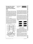
Figure 10.1 depicts the downloader in an ADSP-21020 system. The
downloader receives clock and reset from the system, then it drives the
ADSP-21020’s JTAG TAP, preferably through the standard JTAG header
described in the ADSP-21020 data sheet. This header is recommended to
isolate any circuitry on a board connected to the TAP and thereby
allowing JTAG-based in-circuit emulation during debug of the board
design.
300
JTAG Downloader 10
DMA
DATA
MEMORY
PMA
DMD
PMD
CONTROL
CONTROL
PROGRAM
MEMORY
ADSP-21020
TAP *
JTAG HEADER
TCK
TRST
EPROM
DOWNLOADER
TDI
TMS
CLK
RESET
* = JTAG Test Access Port
Figure 10.1 System Diagram
10.1.1
Details
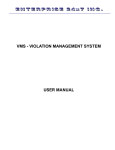
The downloader consists of a 32K x 8 PROM, a 24-bit counter, and two 4:1
multiplexers that drive Test Clock (TCK), Test Reset (TRST), Test Data In
(TDI), and Test Mode Select (TMS) on the ADSP-21020’s JTAG TAP. The
downloader receives CLK and RESET from the existing system. (See
Figure 10.2.) Note that the downloader does not eliminate the need for
power-on reset circuitry on the board. CLK and are connected in parallel
to the ADSP-21020 and the downloader. They both must be driven from
other logic.
301
10 JTAG Downloader
24-bit COUNTER
32K x 8 EPROM
4:1 MUX
Q22:Q23
NC
Q21
D0:D3
A0:A14
Q6:Q20
4
TDI
4:1 MUX
A0:A14
15
D4:D7
TMS
4
ENABLE
S1
S0
Q5
Q4
CLK
MR
Q3
Q2
NC
Q1
NC
Q0
NC
RESET
TCK
(=CLK/16)
TRST
Figure 10.2 Block Diagram
The 24-bit counter is driven by the 20 MHz system clock. Bit 3 generates a
1.25 MHz TCK. Bits 4 and 5 generate select lines for the 4-to-1
multiplexers; bits 6 through 20 drive the PROM address bits; and bit 21 is
used to disable counting when the load is complete. The byte-wide PROM
supplies bits 0-3 to the multiplexer that generates TDI and bits 4-7 to the
multiplexer that generates TMS. TRST is hardwired to system reset.
A parts list is given in Table 10.1. One-time PROMs were chosen because
they are less expensive than their erasable counterparts.
302
(20MHz)
J1-12
CLK
9
8
U1C
U1C
74F00
74F00
10
5
4
U1B
74F00
6
1
2
U1A
74F00
3
11
10
11
10
Q11
Q10
CP
Q9
Q8
74HCT4040
12 STAGE Q7
Q6
BINARY
Q5
RIPPLE
Q4
COUNTER
Q3
Q2
HR
Q1
Q0
U2
Q11
Q10
Q9
Q8
74HCT4040
Q7
12 STAGE
Q6
BINARY
Q5
RIPPLE
Q4
COUNTER
Q3
Q2
HR
Q1
Q0
CP
U3
1
15
14
12
13
4
2
3
5
6
7
9
1
15
14
12
13
4
2
3
5
6
7
9
12
11
A0
A1
A2
A3
A4
A5
A6
A7
A8
A9
A10
A11
A12
A13
A14
VCC
A0-A14
U1D
74F00
13
N.C.
N.C.
N.C.
A5
A4
A3
A2
A1
A0
A14
A13
A12
A11
A10
A9
A8
A7
A6
N.C.
N.C.
U4
A0
A1
A2
A3
A4 27256
A5 32x8
A6 EPROM
A7
A8
A9
A10
A11
A12
A13
A14
20
CE
22
OE
1
VPP
10
9
8
7
6
5
4
3
25
24
21
23
2
26
27
00
01
02
03
04
05
06
07
11
12
13
15
16
17
18
19
3
4
5
6
13
12
11
10
15
1
2
14
U5
74F153
DUAL 4:1 MUX
1C3
1C2
1C1
1C0
2C3
2C2
2C1
2C0
2G
1G
B
A
7
9
VCC
TMS
TCLK
J1-10
/TRST
J1-9
J1-6
J1-1
TDI
J1-8
J1-11
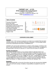
JTAG Downloader 10
Figure 10.3 Prototype Schematic
303
10 JTAG Downloader
Chip
Count
Part No.
Description
Cost†
1
1
1
2
74F00
74F153
HN27C256FP-25T
74HCT4040
Quad NAND gates
Dual 4:1 Multiplexer
32K x 8 One-Time PROM, 250 ns
12-bit binary ripple counter
$ 0.13
$ 0.26
$ 2.13
$ 0.66
TOTAL
$ 3.18
5
Table 10.1 Parts List
For evaluation purposes, you can assemble the hardware on a
daughterboard that receives power, ground, system clock and reset
through a ribbon cable attached to your target or the ADSP-21020 EZLAB board’s 12-pin JTAG header. The ribbon cable can attach to the
standard JTAG header described in the ADSP-21020 data sheet. Since +5 V
power is not available from this connector, the normally missing index pin
1 can be dedicated to power, and its corresponding wire in the ribbon
cable can be jumpered to power on the EZ-LAB board. For complete
documentation of the hardware built in the DSP Applications Lab, see
Figure 10.3 and Figure 10.4.
Note: Analog Devices does not produce or sell this JTAG boot downloader
board. This chapter describes a prototype that was built and tested by the
Applications Engineering Group.
1.8"
U4
U3
U2
U1
1.3"
TOP VIEW
J1
U5
14
16
1
U1
8
1
16
8
9
U2
28
12
1
7
6
9
8
J1
Figure 10.4 Prototype Board Layout
1
U3
7
9
304
1
BOTTOM VIEW
U4
8
16
U5
1
15
14
JTAG Downloader 10
10.1.2
Test Access Port Operations
The software described in the next section takes the output of the ADSP21000 family splitter (spl21k) and generates a file that can be
programmed into the EPROM in one step; you do not need to understand
the operation of the TAP to use it. However, the detailed description of the
TAP behavior that follows gives you the knowledge to debug or modify
this design.
Figure 10.5 depicts all possible states that TMS can take the TAP through.
The states of interest for this project are shaded in Figure 10.5 and are
summarized in Table 10.2.
1
TEST LOGIC
RESET
0
0
RUN TEST /
IDLE
1
1
SELECT DR
SCAN
SELECT IR
SCAN
0
1
0
CAPTURE DR
CAPTURE IR
1
1
0
0
SHIFT DR
SHIFT IR
0
0
1
1
EXIT1 DR
EXIT1 IR
1
0
1
0
PAUSE DR
PAUSE IR
0
0
1
1
EXIT2 DR
EXIT2 IR
1
1
UPDATE DR
1
0
UPDATE IR
1
0
Highlighted states are referred to in Table 12.2
Figure 10.5 JTAG Test Access Port States
305
10 JTAG Downloader
Mnemonic
TLRESET
RT/IDLE
IRSHIFT
IRUPDATE
DRSHIFT
IRUPDATE
Description
Test Logic Reset
Run Test/Idle
Shift TDI into JTAG Shadow Instruction Register (IR)
Update the Instruction Register
Shift TDI into JTAG Shadow Data Register (DR)
Update the Data Register
Table 10.2 JTAG States Used By The Downloader
TMS is responsible for moving the TAP from state to state, while TDI
supplies data when the TAP is in the DRSHIFT or IRSHIFT states. A
sequence of five or more 1s on TMS is guaranteed to return the TAP to the
Test Logic Reset state. A sequence of 0s on TMS is used to hold the TAP in
the DRSHIFT or IRSHIFT states. After bringing the TAP out of TLRESET
and into the RT/IDLE state, TMS stays low unless a state change is taking
place. The rising edge of TCK is used by the TAP to sample both TMS and
TDI.
The data shifted in during the IRSHIFT or DRSHIFT states is stored in a
secondary register. When the TAP moves into the IRUPDATE or
DRUPDATE state, the actual register is updated from the secondary. This
prevents fluctuation on the ADSP-21020 I/O pins during the scan.
The JTAG Instruction Register (IR) controls the mode of operation of the
TAP. In any mode, “state” refers to the TAP’s internal state machine that
governs the operations being performed by the TAP’s I/O pins. The
possible states are given in Table 10.2 and in Figure 10.5. “Mode” refers to
one of the functions (given in Appendix C of the ADSP-21020 User’s
Manual) that the TAP is currently performing. The only modes used for
this project are BYPASS, SAMPLE/PRELOAD and INTEST.
SAMPLE/PRELOAD is used immediately after Test Logic Reset when the
Data Register is still in an unknown state. Once the Data Register is loaded
with known values, the TAP is put in INTEST mode for the remainder of
the download. In INTEST, all input pins drive into the ADSP-21020 and all
output pins drive out to the target board. I/O pins have two separate data
latches—one stores a value to be driven into the ADSP-21020 and the
other holds a value to be driven off-chip. Additionally, an output enable
controls whether or not the output is tri-stated. I/O pins are driven out
only if an associated output enable bit has been set in the scan.
306
JTAG Downloader 10
For complete details on scan bit assignment during DRSHIFT and
IRSHIFT, see Appendix C of the ADSP-21020 User’s Manual. For more
information on JTAG, see the reference section at the end of this chapter.
After power-on reset, the downloader performs the operations shown in
Table 10.3. The operations are controlled by TDI and TMS, which are
generated by the EPROM and MUXs.
1. Set-Up (reset TAP, go to INTEST mode)
a. Enter TLRESET state
b. Enter IRSHIFT state
c. Scan in SAMPLE/PRELOAD instruction (4 bits)
d. Return to RT/IDLE through IRUPDATE
e. Enter DRSHIFT state
f. Scan in active, all memory selects inactive (286 bits)
g. Return to RT/IDLE through DRUPDATE
h. Enter IRSHIFT state
i. Scan in INTEST instruction (4 bits)
j. Return to RT/IDLE through IRUPDATE
2. Scan in instructions until done (in INTEST mode)†
a. Enter DRSHIFT state
b. Scan in next instruction with inactive memory selects (286 bits)
c. Return to RT/IDLE through DRUPDATE
d. Enter DRSHIFT state
e. Scan in same instruction with active memory selects (286 bits)
f. Return to RT/IDLE
3. Exit Download (back to reset state)
a. Inactivate memory selects
b. Return to TLRESET mode
4. Shutdown
a. Disable all operations after counter expires
† = 586 clock cycles/instruction, 467 µsec/instruction at 1.25 MHz TCK
Table 10.3 Downloader Operations
307
10 JTAG Downloader
10.1.3
Timing Considerations
With a 32K x 8 PROM, up to 150 instructions can be downloaded within
105 ms following reset. Although the hardware continues to clock the
EPROM until all 32K bytes have been read, the software provided
generates a TMS bit stream that lets the ADSP-21020 begin loader
execution immediately after scanning the last instruction, even when
fewer than 150 instructions are downloaded. This process occurs by
scanning the TAP back to the Test Logic Reset when the last instruction
has been downloaded. At that point, the ADSP-21020 begins to fetch its
reset instruction at program memory location 0x000008. For a simple
loader of 50 instructions, download could be accomplished in 23 ms. The
downloader hardware would not suspend operations for another 82 ms.
Instead, the ADSP-21020 is running its loader kernel during this time.
The primary speed path in this design is the setup time of TDI and TMS to
TCK. The JTAG specification states that TDI and TMS are sampled on the
rising edge of TCK. This path begins with the 20 MHz system CLK
causing the ripple counter to generate an address for the EPROM that, in
turn, causes the EPROM to generate data. Finally, the multiplexers pass
the data to TDI and TMS. This data must arrive prior to the next rising
edge of TCK.
This speed path (as depicted in Figure 10.6) shows that a setup time of 125
ns is achieved with an 800 ns (1.25 MHz) TCK that is taken from bit 3 of
the 24-bit counter. A higher speed 400 ns (2.5 MHz) TCK, taken from bit 2,
would miss the setup by 275 ns.
308
JTAG Downloader 10
50
CLK
800
TCK
25
S0
50
S1
A0
75
A14
D0:D7
350
OLD DATA
NEW DATA
250
VALID
TMS,TDI
675
125 nsec setup time
NOTE: delays through nand gate which generates TCK and muxes which
generate TMS and TDI are considered negligible in this diagram.
Figure 10.6 Worst-Case Data Setup To Clock Time
309
10 JTAG Downloader
For a 25 MHz system clock, TCK runs at a 640 ns period. A faster EPROM
is required to meet data setup times because the ripple counter delays are
fixed. A 200 ns or faster EPROM is sufficient.
10.2
SOFTWARE
A C program that takes splitter output files (byte-wise stacked format) as
input and produces Motorola Exorciser S-records suitable for burning a
PROM is shown later in this chapter. The component files of this program
are shown in Table 10.4.
Note: The executable must be linked with memory classified as ROM in
the architecture file, or the splitter will not produce the *.stk file
required.
Description
pub21k.c
main program
pub21k.h
constant definitions, included by all code
s2c.c
read byte-wise stacked splitter output file, generate
a simple object code structure
c2b.c
translate object code to EPROM bytes
b2b.c
translate bytes to Motorola S-records
stox.c
function to translate hex string to an integer
Usage
spl21k -a ARCH.ach -f B -pm FILE.exe
# reads .exe
file,
# produces a
.stk file
pub21k ROOT_NAME BANK_ADDR # reads ROOT_NAME.stk,
produces
# ROOT_NAME.s0 records
where: BANK_ADDR = start address of Program memory Bank 1, in hexadecimal
Table 10.4 Source Code Description & Usage
310
JTAG Downloader 10
The commands to produce pub21k for SUN workstations (with the
GCC-compiler), and pub21k.exe for IBM PCs (with the Microsoft Ccompiler) are shown below.
gcc -O -o pub21k pub21k.c s2c.c c2b.c b2b.c stox.c
cl86 /AH /O pub21k.c s2c.c c2b.c b2b.c stox.c /link /
stack:6144
The /AH option for the Microsoft C compiler instructs the compiler to use
the huge memory model because the bytes array of char used in this
program may be larger than the PC segment size. The /O requests code
optimization to be performed while the /stack:6144 linker option
increases the stack size from the default 2048 bytes to 6144 bytes.
10.2.1
TMS & TDI Bit Generation
The bitstream generated by the hardware described earlier is mapped to
individual bit locations in the EPROM. Since TDI comes from the lower
four bits of the EPROM ( Figure 10.2), the first TMS bit generated after
reset is the LSB of the first byte of the EPROM. Because TMS comes from
the upper four bits of the EPROM, the first TMS bit generated after reset is
the fourth bit of the first byte of the EPROM. The general relationship
between a bit in the TMS & TDI bitstream and the EPROM is as follows:
TDI bit N ==> EPROM byte N/4, bit N%4
TMS bit N ==> EPROM byte N/4, bit (N%4)+4
where:
N/4 = integer division by four (fraction discarded),
N%4 = N modulus 4, or the remainder of integer division by 4
Table 10.5 Bitstream/EPROM Byte Relationship
Table 10.5 shows that N*4 bits each of TMS & TDI can be generated from
an N-byte EPROM because each byte of the EPROM contains 4 bits each of
TMS & TDI. Since 586 bits are required to download a single instruction to
PM, (32K*4)/586 = approximately 150 instructions can be downloaded.
311
10 JTAG Downloader
Table 10.6 shows the TMS values used to cause the necessary JTAG state
transitions. The values in the sequence are supplied on the rising edge of
TCK and the final value in parentheses holds the state.
From State
(any)
TLRESET
RT/IDLE
RT/IDLE
DRSHIFT,IRSHIFT
To State
TLRESET
RT/IDLE
DRSHIFT
IRSHIFT
RT/IDLE
TMS Sequence
11111(1)
0(0)
100(0)
1100(0)
110(0)
Table 10.6 TMS Values For State Transitions
Generating the TMS bitstream is simply a concatenation of TMS sequences
shown in Table 10.6. This bitstream is then packed into EPROM bytes
according to the formulas shown in Table 10.5. Detailed examples of the
TMS bitstream are given later as well as shown in Figures 10.7-10.9.
The TDI bitstream is a sequence of 0s while TMS is inducing state changes
followed by a pattern of data bits to be scanned into the IR or DR during
IRSHIFT or DRSHIFT. Table 10.7 summarizes the relevant TDI values.
Instruction Register Values (IRSHIFT)
JTAG State
Sample/Preload
Intest
BITS
4321
0001
0011
Data Register Values (DRSHIFT)
Signal
RESETPMWRPMD47:PMD0
PMA0:PMA23
PMS0PMS1FLAG0OE
FLAG1OE
FLAG2OE
FLAG3OE
Bit Scan Position
7
11
15-109, odd bits only
257-280
283
282
248
242
233
228
Table 10.7 TDI Values For IRSHIFT & DRSHIFT
312
JTAG Downloader 10
These values are used in the C-code header file pub21k.h.The TDI
bitstream is formed by concatenating these patterns together with 0s
during state changes. Appendix C of the ADSP-21020 User’s Manual lists
all 286 scan locations of the DR.
All bits not in Table 10.7 are set to one. This assures that all I/O output
enables (active high) are ON, and all memory strobes and interrupts
(active low) are OFF. The scan locations in Table 10.7 may be set to either
zero or one during DRSHIFT. A benefit of using 1s on all remaining bits is
that it offers a clear visual indicator during hardware debug that
DRSHIFT is under way. This is illustrated in Figures 10.7-10.9.
10.2.2
Software Example
The source code at the end of this chapter, kernel.asm , is an example of
a bootstrap loader that is capable of loading the user’s application by
reading an EPROM memory-mapped in data memory. The procedure
necessary to generate a Motorola S-record file to burn the downloader
EPROM is outlined with the assumption that you are familiar with the
ADSP-21020’s architecture files, assembler, linker, and PROM splitter. See
the ADSP-21000 Family Assembler Tools & Simulator Manual for complete
details.
The system architecture assumed for this example is a hypothetical board
with 128K-words of program memory arranged in two 64K-word banks.
The address range of bank zero is 0x000000 —> 0x00FFFF and bank one is
0x010000 —> 0x01FFFF. The bulk of the loader code is stored in the upper
256 words of the higher bank (starting at 0x01FF00). To invoke this loader,
the ADSP-21020 must be programmed to jump to it from the reset service
routine that begins at location 0x000008 in bank zero. The architecture file,
kernel.ach, for this system is as follows.
.SYSTEM
kernel;
.PROCESSOR =ADSP21020;
.SEGMENT /ROM /BEGIN=0x000008 /END=0x0000FF /PM rst_svc;
.SEGMENT /ROM /BEGIN=0x01FF00 /END=0x01FFFF /PM loader;
.ENDSYS;
Table 10.8 kernel.ach - Architecture File Used With kernel.asm
313
10 JTAG Downloader
The source code must first be assembled and linked with the commands
asm21k kernel
ld21k -a kernel.ach kernel
to produce the executable kernel.exe. If you make any modifications
to the loader given in the C source code listings at the end of this chapter,
you may want to verify its behavior on the ADSP-21020 simulator.
Now you are ready to burn a downloader EPROM. The command
spl21k -a kernel -f B -pm kernel
produces kernel.stk that pub21k needs to create the S-record. The
file kernel.stk , listed in Table 10.9, looks like the following:
20008000000000080000002A
0FE000000021
0FF000008421
0F3000000000
0F3800000000
0F490001FF4B
06BE0001FF3A
063E0001FF00
200080000001FF00000001D4
0F2000000001
0F2100000000
0F22FFFFFFFF
.
.{ many lines omitted }
.
0A3E04000000
12020001FF4B
527F80802012
000000000000
000000000000
000000000000
000000000000000000000000
Table 10.9 kernel.stk - Stacked-format spl21k Output
314
JTAG Downloader 10
The format of kernel.stk is discussed in s2c.c , but it is not
necessary to know the format to use pub21k . The command
pub21k kernel 10000
generates kernel.s0 , a Motorola S-record that can be used to burn the
EPROM on a Data-I/O Unisite system, for example. The “10000”
indicates that 0x10000 is the hexadecimal start address of Program
Memory Bank One. The file, kernel.s0 , is shown in Table 10.10
byte
address
data bytes
+—— checksum
\
|
|
+—++———+———+ |
| ||
| |
S10B0000F0F06000B10C0F00E8
S10B000800000000010F0F0EBF
S10B00100B0F070F0E0F0F0F79
S10B00180F0F0F0F0F0F0F0F64
S10B00200F0F0F0F0F0F0F0F5C
S10B00280F0F0F0F0F0B0A0A62
S10B00300A0E0505070505058C
.
.{ many lines omitted }
.
S10BFFD0F0F0F0F0F0F0F0F0A5
S10BFFD8F0F0F0F0F0F0F0F09D
S10BFFE0F0F0F0F0F0F0F0F095
S10BFFE8F0F0F0F0F0F0F0F08D
S10BFFF0F0F0F0F0F0F0F0F085
S10BFFF8F0F0F0F0F0F0F0F07D
S9030000FC
Table 10.10 kernel.s0 - pub21k Output Used To Burn Downloader EPROM
315
10 JTAG Downloader
10.2.3
Summary: How To Make The EPROM
1. Create kernel.asm , the assembly-language source file
2. Create kernel.ach , the architecture file that describes the target
hardware
3. Issue commands to create kernel.s0 from kernel.asm :
asm21k kernel
ld21k -a kernel kernel
spl21k -a kernel -f B -pm kernel
pub21k kernel 10000
4. Burn EPROM using kernel.s03 .
10.3
DETAILED TMS & TDI BEHAVIOR
This section is intended as an aid to anyone who needs to debug an
EPROM-based downloader like the one described here. Since there is little
external evidence of the internal state of the ADSP-21020 when it is under
JTAG control, it is extremely important to understand what TMS and TDI
looks like in a real system.
Figures 10.7-10.9 depict various operations of the downloader. Viewing
these figures along with Table 10.3 aids in the understanding of the
following paragraphs.
Figure 10.7 depicts the operation of TMS, TDI, TCLK after system reset
goes inactive through the start of the first Data Register scan, steps 1a-1f in
Table 10.3. Time stamps in microseconds are referenced from the first
rising edge of TCLK generated by the EZ-BOOT hardware and are valid
for a 20 MHz system clock. Eight 1s are clocked in on TMS to guarantee
that the TAP is in the TLRESET state (1a). Next, a transition is made
through RT/IDLE to IRSHIFT, when the SAMPLE/PRELOAD instruction
is scanned in on TDI (1b-1c). After another transition through RT/IDLE,
the DRSHIFT state is entered and the first Data Register scan begins
(1c-1f).
316
to DRSHIFT
to RT/IDLE
hold IRSHIFT
to RT/IDLE
to IRSHIFT
to TLRESET
JTAG Downloader 10
TMS
TDI
2222222
8888888
6543210
TCLK
800 ns
scan bit
numbers
0 µs
8 µs
16 µs
222222
665555
109876
P
M
A
2
3
24 µs
P
M
A
0
3
32 µs
P
M
A
0
0
40 µs
2
4
8
2
4
2
F
L
A
G
0
0
E
F
L
A
G
1
0
E
48 µs
56 µs
Figure 10.7 TMS & TDI Timing From RESET Through Start Of First Scan Of DR
Scan bit numbers corresponding to scan bit assignments in the JTAG
Appendix of the ADSP-21020 User’s Manual are shown below the TDI
bitstream. Bits 286-281 are all 1s, then bits 280-257 (PMA[23:0]) are 0s with
the exception of bit 260 (PMA[3]). This sequence corresponds to an
instruction address of 8, but it is irrelevant in this DRSHIFT operation
since memory strobes are inactive. The purpose of the first data register
scan is to bring the data register into a known state before changing the
TAP from the SAMPLE/PRELOAD mode to INTEST mode. No activity
occurs on the ADSP-21020’s pins until the SAMPLE/PRELOAD mode is
over and INTEST mode is entered. The first instruction of the loader
kernel, which is located at instruction 8, is scanned in again during the
next DRSHIFT, also with inactive memory strobes.
317
10 JTAG Downloader
to DRSHIFT
to RT/IDLE
hold IRSHIFT
to IRSHIFT
to RT/IDLE
hold DRSHIFT
Figure 10.8 depicts the completion of the first Data Register scan (1f-1g)—
the scanning in of the INTEST mode into the Instruction Register (1h-1j)
and the start of the second Data Register scan (2a-2b). The figure also
depicts the change of state of the program memory interface (collectively,
the PMWR-, PMS0-, PMS1-, PMA[23:0], and PMD[47:0] pins) when the
INTEST mode has been established.
TMS
TDI
2222222
8888888
6543210
8 7654321
R
E
S
E
T
scan bit
numbers
TCLK
222 222
665 555
109 876
P
M
A
2
3
P
M
A
0
3
P
M
A
0
0
800 ns
PM
interface
240 µs
TRI-STATE
248 µs
RESET- active, STROBES inactive
256 µs
264 µs
272 µs
280 µs
288 µs
292 µs
Figure 10.8 TMS & TDI Timing From End Of First Scan To Start Of Second Scan
In this Data Register scan, the first instruction is scanned in with inactive
memory strobes. Labeling of scan bit numbers is similar to Figure 10.7.
318
JTAG Downloader 10
TMS
TMS
TDI
TDI
TDI
TCLK
TCLK
TCLK
hold TLRESET
to TLRESET
to RT/IDLE
to TLRESET
hold TLRESET
to RT/IDLE
hold DRSHIFT
hold DRSHIFT
to RT/IDLE
to DRSHIFT
hold DRSHIFT
The left graphic in Figure 10.9 depicts the completion of the second Data
Register scan (2b-2c) through the start of the third scan. This operation is
identical to the n-th and (n+1)-th scan for all n > 1 until the last instruction
is scanned in. (Except of course the timestamp changes.) Each DRSHIFT,
including the return back to RT/IDLE, requires 291 TCK cycles or 232.8
µs. The third Data Register scan is a repeat scan of the first instruction
with active memory strobes (2d-2f).
TMS
800ns
OLD STATE
NEW STATE
PMRD
800ns
480 µs
488 µs
492 µs
Boundary between 2nd and 3rd scan,
or nth and (n+1)th scan
End of Last Scan
FETCH 0xB, EXEC 0x9
PM
interface
FETCH 0x9
NEW STATE
FETCH 0x8
OLD STATE
FETCH 0xA, EXEC 0x8
PM
interface
End of Last Scan (magnified scale)
Figure 10.9 Other TMS & TDI Timing
The remaining graphics in Figure 10.9 show the end of the last scan (2f-3b)
at two magnifications. Here the TMS line moves the TAP out of RT/IDLE
to the TLRESET state making the ADSP-21020 free to begin executing
instructions. These instructions are executed even as TCLK continues to
drive TMS=1 into the TAP until the downloader hardware has read all
EPROM locations.
The magnified view at the right of Figure 10.9 shows the PMRD- line
becoming active with the first fetch of the reset vector at program memory
location 0x000008. The PMRD- behavior depicted assumes that the first
instruction fetched at location 0x000008 sets the PMWAIT register to zero
wait states. Thus 50 ns fetch cycles begin after the instruction at 0x000008
is executed.
319
10 JTAG Downloader
10.3.1
Code Listings
10.3.2
pub21k.h
#include
#include
#include
#include
<stdio.h>
<stddef.h>
<malloc.h>
<string.h>
/*——————————————————————————————————————
Constant Definitions
——————————————————————————————————————*/
#define EPROMSZ
32768L
/* EPROM Size in bytes
#define LINELEN
256
/* Maximum Line Length
#define MAXLINES
256
/* Maximum lines of code
#define ARGCHARS
33
/* Maximum characters in an argument
*/
*/
*/
*/
/* bank
#define
#define
#define
*/
*/
*/
selects in code structure */
BANK0
0
/* Bank 0 == PMS0 active
BANK1
1
/* Bank 1 == PMS0 active
ENDFLG
-1
/* flag indicating end of code
/* strobe states for scanDR */
#define INACTIVE
0
#define ACTIVE
1
/*——————————————————————————————————————
Scan Path Definitions
——————————————————————————————————————*/
/* define TMS values to sequence to next state */
#define TLRESET
“11111111”
/* from any state to TLRESET state
#define RST2RTI
“0”
/* from TLRESET to RT/IDLE
#define RTI2DRS
“100”
/* from RT/IDLE to DRSHIFT
#define RTI2IRS
“1100”
/* from RT/IDLE to DRSHIFT
#define S2RTI
“110”
/* from DRSHIFT or IRSHIFT to RT/IDLE
/* define TDI values for Instruction Register
/* Note: these appear bit-reversed from the user’s guide since the
/*
user’s guide shows them with the lsb on the LEFT
#define PRELD
“0001”
#define INTEST
“0011”
/* mapping of 21020’s pins to scan path */
#define DRLOCS
286
#define RESET
(DRLOCS - 7)
#define PMWR
(DRLOCS - 11)
#define PMA(offset)
(DRLOCS - (257+offset))
#define PMD(offset)
(DRLOCS - (109 - 2*offset))
#define PMS0
(DRLOCS - 283)
#define PMS1
(DRLOCS - 282)
#define FLG3
(DRLOCS - 235)
#define FLG2
(DRLOCS - 237)
#define FLG1
(DRLOCS - 239)
#define FLG0
(DRLOCS - 241)
320
*/
*/
*/
*/
*/
*/
*/
*/
JTAG Downloader 10
#define
#define
#define
#define
#define
FLG3OE
FLG2OE
FLG1OE
FLG0OE
DMD(offset)
(DRLOCS
(DRLOCS
(DRLOCS
(DRLOCS
(DRLOCS
-
228)
233)
242)
248)
(112 + 2*offset))
/*—————————————————————————————————————
Macros for Bit Manipulation in EPROM bytes array
—————————————————————————————————————*/
#define SET_TDI(index,offset) \
bytes[(index+offset)/4] |= (1 << ((index+offset)%4))
#define SET_TMS(index,offset) \
bytes[(index+offset)/4] |= (16 << ((index+offset)%4))
#define CLR_TDI(index,offset) \
bytes[(index+offset)/4] &= ~(1 << ((index+offset)%4))
#define CLR_TMS(index,offset) \
bytes[(index+offset)/4] &= ~(16 << ((index+offset)%4))
/*——————————————————————————————————————
Typedefs
——————————————————————————————————————*/
typedef struct objcode {
char bank;
/* structure describing object code to be
unsigned long pma;
/*
scanned into Program Memory
unsigned long pmdu;
unsigned long pmdl;
} OBJCODE;
*/
*/
typedef struct header_t {
unsigned char width;
unsigned char version;
unsigned char flags;
unsigned char uflags;
unsigned long address;
unsigned long length;
} HEADER;
typedef unsigned long ULONG;
#ifdef MSDOS
typedef unsigned char huge BYTE_ARRAY;
#define CALLOC halloc
#else
typedef unsigned char BYTE_ARRAY;
#define CALLOC calloc
#endif
(listing continues on next page)
321
10 JTAG Downloader
/*———————————————————————————————————————
Function prototypes
———————————————————————————————————————*/
int getData(FILE *ip, HEADER *hdr, ULONG bankaddr, OBJCODE *code);
int getHeader(FILE *ip, HEADER *hdr);
void spl2code(FILE *ip, ULONG bankaddr, OBJCODE *code);
void changeState(char *str, BYTE_ARRAY *bytes, long *bitindex);
void scanIR(char *str, BYTE_ARRAY *bytes, long *bitindex);
void scanDR(int num, char strobeState, OBJCODE *code,
BYTE_ARRAY *bytes, long *bitindex);
void initializeTAP(OBJCODE *code, BYTE_ARRAY *bytes, long *bitindex);
void scanCode(int num, OBJCODE *code, BYTE_ARRAY *bytes, long *bitindex);
void terminateTAP(int num, OBJCODE *code, BYTE_ARRAY *bytes, long *bitindex);
void code2bytes(OBJCODE *code, BYTE_ARRAY *bytes);
void makeSrecord(FILE *outfilep, long num, BYTE_ARRAY *bytes);
void makeStail(FILE *outfilep);
void bytes2burn(BYTE_ARRAY *bytes, FILE *outfilep);
ULONG stox (char *str, int chars);
Listing 10.1 pub21k.h
10.3.3
pub21k.c
/*—————————————————————————————————————
FILE:
pub21k.c
DESCRIPTION:
Reads spl21k stacked-format output files, writes Motorola
Exorciser-format S-records for burning EPROMs for the
EPROM-based 21020 JTAG Downloader Board.
REQUIRED:
s2c.c, c2b.c, b2b.c, stox.c
DATE:
6/13/91
—————————————————————————————————————*/
#include “pub21k.h”
/*—————————————————————————————————————
Main program
—————————————————————————————————————*/
main (int argc, char *argv[])
{
OBJCODE
code[MAXLINES];
BYTE_ARRAY *bytes;
char
infile[ARGCHARS];
char
outfile[ARGCHARS];
FILE
*ip, *op;
long
i;
ULONG
bankaddr=0xFFFFFF;
/* Process arguments:
/*
argv[1] = root name of files
/*
argv[2] = start address of Program Memory Bank 1, in hex
switch (argc) {
case 3:
strncpy (infile, argv[1], ARGCHARS-1);
strcat (infile, “.stk”);
322
*/
*/
*/
JTAG Downloader 10
bankaddr = stox(argv[2], ARGCHARS);
strncpy (outfile, argv[1], ARGCHARS-1);
strcat (outfile, “.s0”);
break;
default:
fprintf (stderr,
“Usage:
pub21k ROOT_NAME BANK_ADDDR\n”);
fprintf (stderr,
“Description: reads ROOT_NAME.stk, generates ROOT_NAME.s0\n”);
fprintf (stderr,
“Notes:
generate ROOT_NAME.stk with \”spl21k -f B -pm
ROOT_NAME\”\n”);
fprintf (stderr,
“
BANK_ADDR = start address of PM Bank 1, in hex\n”);
exit(1);
}
#ifdef DEBUG
printf (“main: using input file %s\n”, infile);
printf (“main: using bank addr
%08.8X\n”, bankaddr);
printf (“main: using output file %s\n”, outfile);
#endif
/* Allocate memory for bytes array */
if ((bytes = (BYTE_ARRAY *)CALLOC(EPROMSZ, sizeof(BYTE_ARRAY))) == NULL){
fprintf (stderr, “ERROR: can’t allocate memory for bytes array\n”);
exit(1);
}
/* Initialization */
for (i=0; i<EPROMSZ; i++) *(bytes+i) = (char) NULL;
for (i=0; i<MAXLINES; i++) code[i].bank = ENDFLG;
if ((ip = fopen(infile,”r”)) == NULL) {
fprintf (stderr, “ERROR: Can’t open input file %s\n”, infile);
exit(1);
}
if ((op = fopen(outfile,”w”))==NULL) {
fprintf (stderr, “ERROR: Can’t open output file %s\n”, outfile);
exit(1);
}
/* read .stk file (stacked format), put results into code array */
spl2code(ip, bankaddr, code);
/* translate code into bytes for PROM */
code2bytes(code, bytes);
/* translate PROM bytes into Moto’s S-record format */
bytes2burn(bytes, op);
}
Listing 10.2 pub21k.c
323
10 JTAG Downloader
10.3.4
s2c.c
/*———————————————————————————————————————
FILE:
s2c.c
DESCRIPTION:
Reads splitter stacked format file, creates code structure.
Part of pub21k.c program.
DATE:
6/13/91
———————————————————————————————————————*/
#include “pub21k.h”
#define PMBYTES
6
/*———————————————————————————————————————
SUBROUTINE:
getData
DESCRIPTION:
gets Data from a splitter stacked format file
The format of each line is simply 12 characters “UUUULLLLLLLL”,
where “UUUU” is the 4-character (2 bytes) upper bits of the
instruction, and “LLLLLLLL” is the 8-character lower bits.
———————————————————————————————————————*/
int getData(FILE *ip, HEADER *hdr, ULONG bankaddr, OBJCODE *code)
{
int
i;
char
upper[5];
char
lower[9];
char
line[LINELEN];
unsigned long
addr;
int
max;
static int
codeindex = 0;
addr = hdr->address;
max = hdr->length/PMBYTES;
for (i=0; i<max; i++, addr++, codeindex++) {
if (fgets(line,LINELEN,ip)==NULL) {
fprintf (stderr, “ERROR: Premature EOF in input file\n”);
exit(1);
}
if (sscanf(line, “%4s%8s”, upper, lower) != 2) return (-1);
if (addr < bankaddr) {
(code+codeindex)->bank = BANK0;
} else {
(code+codeindex)->bank = BANK1;
}
(code+codeindex)->pma = addr;
(code+codeindex)->pmdl = stox(lower,9);
(code+codeindex)->pmdu = stox(upper,5);
}
return(0);
}
/*———————————————————————————————————————
324
JTAG Downloader 10
SUBROUTINE:
DESCRIPTION:
getHeader
gets a splitter stacked format header
The header format is “WWVVFFUUAAAAAAAALLLLLLLL”, where
WW = width of address & length fields
(2 characters)
VV = version #
(2 characters)
FF = splitter flags
(2 characters)
UU = user flags
(2 characters)
AAAAAAAA = address
(8 characters)
LLLLLLLL = length
(8 characters)
———————————————————————————————————————*/
int getHeader(FILE *ip, HEADER *hdr)
{
char
line[LINELEN], *lp;
lp = line;
if (fgets(line,LINELEN,ip)==NULL) return (-1);
/* build header
hdr->width
hdr->version
hdr->flags
hdr->uflags
hdr->address
hdr->length
structure, although only address and length are used */
= (char) stox(lp, 2); lp+=2;
= (char) stox(lp, 2); lp+=2;
= (char) stox(lp, 2); lp+=2;
= (char) stox(lp, 2); lp+=2;
=
stox(lp, hdr->width/4); lp+=hdr->width/4;
=
stox(lp, hdr->width/4);
return(0);
}
/*———————————————————————————————————————
SUBROUTINE:
spl2code
DESCRIPTION:
read splitter stacked format file, generate code structure
———————————————————————————————————————*/
void spl2code(FILE *ip, ULONG bankaddr, OBJCODE *code)
{
HEADER hdr;
/* read headers until they’re gone, put data into code structure */
while (!getHeader(ip,&hdr)) {
#ifdef DEBUG
printf (“spl2code: header addr=%08.8X, length(bytes) = %08.8X\n”,
hdr.address, hdr.length);
#endif
/* get data following current header */
if (getData(ip, &hdr, bankaddr, code)) {
fprintf (stderr, “ERROR: data format in input file\n”, ip);
exit(1);
}
}
}
Listing 10.3 s2c.c
325
10 JTAG Downloader
10.3.5
c2b.c
/*—————————————————————————————————————
FILE:
c2b.c
DESCRIPTION:
Translates object code structure to EPROM bytes.
Part of pub21k.c program.
AUTHOR:
Jim Donahue, Analog Devices DSP Division (617) 461-3672
DATE:
6/13/91
—————————————————————————————————————*/
#include “pub21k.h”
/*—————————————————————————————————————
SUBROUTINE:
changeState
DESCRIPTION:
change state of Test Access Port
—————————————————————————————————————*/
void changeState(char *str, BYTE_ARRAY *bytes, long *bitindex)
{
#ifdef DEBUG
printf (“changeState: bitindex = %d, byte = %X, index = %X\n”,
*bitindex, *bitindex/4, *bitindex%4);
#endif
while (*str != (char) NULL) {
if (*str++ == ‘1’)
SET_TMS(*bitindex,0);
(*bitindex)++;
}
}
/*—————————————————————————————————————
SUBROUTINE:
scanIR
DESCRIPTION:
scan into Test Access Port Instruction register
—————————————————————————————————————*/
void scanIR(char *str, BYTE_ARRAY *bytes, long *bitindex)
{
#ifdef DEBUG
printf (“scanIR: bitindex = %d, byte = %X, index = %X\n”,
*bitindex, *bitindex/4, *bitindex%4);
#endif
while (*str != (char) NULL) {
if (*str++ == ‘1’)
SET_TDI(*bitindex,0);
(*bitindex)++;
}
(*bitindex)—;
/* must correct bitindex since exiting scan state
*/
/*
(TMS=1) must coincide with sending last datum */
}
/*—————————————————————————————————————
SUBROUTINE:
scanDR
DESCRIPTION:
scan into Test Access Port Data register
—————————————————————————————————————*/
326
JTAG Downloader 10
void scanDR(int num, char strobeState, OBJCODE *code,
BYTE_ARRAY *bytes, long *bitindex)
{
int
i;
#ifdef DEBUG
printf (“scanDR: bitindex = %d, byte = %X, index = %X”,
*bitindex, *bitindex/4, *bitindex%4);
if (strobeState) printf (“, active strobes\n”);
else printf (“, inactive strobes\n”);
#endif
/* Set background mask of all “1”s - this assures inactive (high)
/*
memory strobes and interrupts.
/* All further operations will be selective clearing of TDI bits
for (i=0; i<DRLOCS; i++)
SET_TDI(*bitindex,i);
*/
*/
*/
/* RESET, FLAG0-3 enables always active low */
CLR_TDI(*bitindex,RESET);
CLR_TDI(*bitindex,FLG0OE);
CLR_TDI(*bitindex,FLG1OE);
CLR_TDI(*bitindex,FLG2OE);
CLR_TDI(*bitindex,FLG3OE);
if (strobeState==ACTIVE) {
/* Activate bank selects and write lines */
if ((code+num)->bank==BANK0)
CLR_TDI(*bitindex,PMS0);
else
CLR_TDI(*bitindex,PMS1);
CLR_TDI(*bitindex,PMWR);
}
for (i=0;i<24;i++)
if (!((code+num)->pma & (1<<i)))
CLR_TDI(*bitindex,PMA(i));
for (i=0;i<32;i++)
if (!((code+num)->pmdl & (1<<i)))
CLR_TDI(*bitindex,PMD(i));
for (i=32;i<48;i++)
if (!((code+num)->pmdu & (1<<(i-32))))
CLR_TDI(*bitindex,PMD(i));
/* DMD[15:0] used as a flag to indicate which instruction
/* is being scanned down
for (i=0;i<8;i++)
if (!(num & (1<<i)))
CLR_TDI(*bitindex,DMD(i));
*/
*/
(listing continues on next page)
327
10 JTAG Downloader
/* must correct bitindex since exiting scan state (TMS=1)
/*
must coincide with sending last datum
*bitindex = *bitindex + DRLOCS - 1;
*/
*/
}
/*——————————————————————————————————————
SUBROUTINE:
initializeTAP
DESCRIPTION:
initialize Test Access Port
——————————————————————————————————————*/
void initializeTAP(OBJCODE *code, BYTE_ARRAY *bytes, long *bitindex)
{
/* reset TAP, enter RT/IDLE state */
changeState(TLRESET, bytes, bitindex);
changeState(RST2RTI, bytes, bitindex);
/* enter IRSHIFT state, scan in SAMPLE/PRELOAD instruction */
changeState(RTI2IRS, bytes, bitindex);
scanIR(PRELD, bytes, bitindex);
changeState(S2RTI, bytes, bitindex);
/* enter DRSHIFT state, scan in RESET active, mem. strobes inactive */
changeState(RTI2DRS, bytes, bitindex);
scanDR(0, INACTIVE, code, bytes, bitindex);
changeState(S2RTI, bytes, bitindex);
/* enter IRSHIFT state, scan in INTEST instruction */
changeState(RTI2IRS, bytes, bitindex);
scanIR(INTEST, bytes, bitindex);
changeState(S2RTI, bytes, bitindex);
}
/*——————————————————————————————————————
SUBROUTINE:
scanCode
DESCRIPTION:
scan in instructions
——————————————————————————————————————*/
void scanCode(int num, OBJCODE *code, BYTE_ARRAY *bytes, long *bitindex)
{
#ifdef DEBUG
printf (“scanCode: processing code line %d\n”, num);
#endif
328
/* enter DRSHIFT state, scan in instruction with inactive strobes
changeState(RTI2DRS, bytes, bitindex);
scanDR(num, INACTIVE, code, bytes, bitindex);
changeState(S2RTI, bytes, bitindex);
*/
/* enter DRSHIFT state, scan in instruction with ACTIVE strobes
changeState(RTI2DRS, bytes, bitindex);
scanDR(num, ACTIVE, code, bytes, bitindex);
changeState(S2RTI, bytes, bitindex);
*/
JTAG Downloader 10
/* enter DRSHIFT state, scan in instruction with inactive strobes
changeState(RTI2DRS, bytes, bitindex);
scanDR(num, INACTIVE, code, bytes, bitindex);
changeState(S2RTI, bytes, bitindex);
*/
}
/*——————————————————————————————————————
SUBROUTINE:
terminateTAP
DESCRIPTION:
terminate Test Access Port
——————————————————————————————————————*/
void terminateTAP(int num, OBJCODE *code, BYTE_ARRAY *bytes, long *bitindex)
{
/* enter DRSHIFT state, scan in last instruction with inactive strobes */
changeState(RTI2DRS, bytes, bitindex);
scanDR(num, INACTIVE, code, bytes, bitindex);
changeState(S2RTI, bytes, bitindex);
/* fill remainder of EPROM with 1’s in TMS bits. This will */
/*
hold TAP in TLRESET
*/
#ifdef DEBUG
printf (“terminateTAP: setting remaining TMS bits\n”);
printf (“terminateTAP: bitindex = %d, byte = %X, index = %X\n”,
*bitindex, *bitindex/4, *bitindex%4);
#endif
while (*bitindex < (EPROMSZ*4L)) {
SET_TMS (*bitindex, 0);
(*bitindex)++;
}
}
/*——————————————————————————————————————
SUBROUTINE:
code2bytes
DESCRIPTION:
translates code structure to EPROM bytes
——————————————————————————————————————*/
void code2bytes(OBJCODE *code, BYTE_ARRAY *bytes)
{
int
i;
long
bitindex = 0L;
/* initialize the Test Access Port
*/
initializeTAP(code, bytes, &bitindex);
/* process all valid entries in code structure */
for (i=0; i<MAXLINES && code[i].bank!=ENDFLG; i++) {
scanCode(i, code, bytes, &bitindex);
}
/* we are outta here!
*/
terminateTAP(i-1, code, bytes, &bitindex);
}
Listing 10.4 c2b.c
329
10 JTAG Downloader
10.3.6
b2b.c
/*—————————————————————————————————————————
FILE:
b2b.c
DESCRIPTION:
Reads bytes created by c2b.c, generates Motorola
Exorciser-format S-records for burning EPROMs.
Part of pub21k.c program.
AUTHOR:
Jim Donahue, Analog Devices DSP Division (617) 461-3672
DATE:
6/13/91
—————————————————————————————————————————*/
#include “pub21k.h”
#define BYTES_PER_RECORD
8
/*—————————————————————————————————————————
SUBROUTINE:
makeSrecord
DESCRIPTION:
make an S-record format data record
The S-record format is “TTLLAAAADDDDDDDDDDDDDDDDCC”, where
TT = 2-character type of S record = S1
LL = 4-char length, in bytes, of address,data, and checksum fields
AAAA = 4-character address
DDDDDDDDDDDDDDDD = 8 bytes of EPROM data
CC = checksum = 1’s comp of least sig. byte of sum of all bytes
EXCEPT the type byte.
All fields are hex values.
—————————————————————————————————————————*/
void makeSrecord(FILE *outfilep, long num, BYTE_ARRAY *bytes)
{
long
i;
ULONG
chksum;
chksum = BYTES_PER_RECORD + 3;
chksum += (num & 0xFF);
chksum += ((num & 0xFF00) >> 8);
fprintf (outfilep, “S1%02.2X%04.4X”, BYTES_PER_RECORD+3, num);
for(i=num; i<num+BYTES_PER_RECORD;i++){
fprintf(outfilep, “%02.2X”, bytes[i]);
chksum += bytes[i];
}
fprintf(outfilep, “%02.2X\n”, (~chksum) & 0xFF);
}
/*—————————————————————————————————————————
SUBROUTINE:
makeStail
DESCRIPTION:
make a S-record format termination record
This is a canned terminator record from Motorola’s description of
S-records.
—————————————————————————————————————————*/
330
JTAG Downloader 10
void makeStail(FILE *outfilep)
{
fprintf(outfilep, “S9030000FC\n”);
}
/*—————————————————————————————————————————
SUBROUTINE:
bytes2burn
DESCRIPTION:
turn PROM bytes into .S0 format for PROM burner
—————————————————————————————————————————*/
void bytes2burn(BYTE_ARRAY *bytes, FILE *outfilep)
{
long i;
for(i=0; i<EPROMSZ; i+=BYTES_PER_RECORD) {
makeSrecord(outfilep, i, bytes);
}
makeStail(outfilep);
}
Listing 10.5 b2b.c
10.3.7
stox.c
/*————————————————————————————————————————
FILE:
stox.c
DESCRIPTION:
converts hexadecimal string to integer
AUTHOR:
Jim Donahue, Analog Devices DSP Division (617) 461-3672
DATE:
6/17/91
————————————————————————————————————————*/
#ifndef ULONG
typedef unsigned long ULONG;
#endif
ULONG stox (char *str, int chars)
{
ULONG val = 0L;
for ( ; chars>0 && *str!=’\0'; chars—, str++) {
val = val << 4;
if (*str>=’0' && *str<=’9')
val += (ULONG) (*str-’0');
else if (*str>=’a’ && *str<=’f’)
val += (ULONG) (*str-’a’+10);
else if (*str>=’A’ && *str<=’F’)
val += (ULONG) (*str-’Adata memory +10);
}
return(val);
}
Listing 10.6 stox.c
331
10 JTAG Downloader
10.3.8
Loader Kernel
/*———————————————————————————————————————
| Loader Kernel
|
| Performs Load of an application program from a byte-wide EPROM in DM.
|
| Has a checksum calculator to verify that the loader has not been corrupted
| by system problems.
|
| Data in byte-wide EPROM consists of 4, 5 and 6 byte words starting with
| least significant byte. Data is arranged in blocks consisting of a header
| followed by data:
|
| ADDRESS
4 bytes
start address of data block
| LENGTH/SPACE
4 bytes
length of block in words, plus
|
bit 31 = PM select if 1, DM if 0
|
DATA
—
|
DATA
\
|
.
\
|
.
|— 5 bytes/word (DM) / 6 bytes/word(PM)
|
.
/
|
/
|
DATA
—
|
| ADDRESS
| LENGTH/SPACE
|
|
DATA
|
.
|
.
|
.
| etc.
|
| RETURN_ADDRESS
| LENGTH/SPACE
|
|
| The loader stops processing data from the EPROM when it reads a header
| with LENGTH/SPACE = 0x00000000. From there, it jumps to RETURN_ADDRESS.
|
*—————————————————————————————————————*/
#define EPROM_ADDR
0x18000
/*——————————————————————————————————————
| Reset Service Routine
*—————————————————————————————————————*/
.SEGMENT /PM
rst_svc;
rst_svc:
PMWAIT=0x0021;
/* no wait states,internal ack only
DMWAIT=0x8421;
/* no wait states,internal ack only
332
*/
*/
JTAG Downloader 10
goldchk:
/* Run the checksum calculator, storing result in golden
/*
checksum memory location
b9=goldsum;
call checksum;
*/
*/
/* Now run the loader itself */
jump loader;
.ENDSEG;
/*——————————————————————————————————————
| The Loader itself
*—————————————————————————————————————*/
.SEGMENT /PM
loader;
loader:
m0 = 1;
m1 = 0;
m2 = -1;
m8 = 1;
m9 = 0;
b1 = EPROM_ADDR;
l0 = 0;
l1 = 0;
l8 = 0;
r15 = 31;
loadlp:
/* Process the header */
/* r1 <== Assembled
r0=dm(i1,m0);
r1=fdep r0 by 0:8,
r1=r1 or fdep r0 by
r1=r1 or fdep r0 by
r1=r1 or fdep r0 by
destination address */
8:8,
16:8,
24:8;
r0=dm(i1,m0);
r0=dm(i1,m0);
r0=dm(i1,m0);
/* r2 <== Data length and PM/DM flag */
r0=dm(i1,m0);
r2=fdep r0 by 0:8,
r0=dm(i1,m0);
r2=r2 or fdep r0 by 8:8,
r0=dm(i1,m0);
r2=r2 or fdep r0 by 16:8,
r0=dm(i1,m0);
r2=r2 or fdep r0 by 24:8;
/* if length is zero, loader is done */
r2 = pass r2;
if eq jump done;
/* check PM/DM flag */
btst r2 by r15;
if sz jump dmload;
pmload:
r2 = bclr r2 by r15, b8 = r1;
/* clear the flag after test
/* set destination address
*/
*/
(listing continues on next page)
333
10 JTAG Downloader
pmlp:
dmload:
/* Read and assemble PM data bytes until done.
/* Assemble lower 16 bits in px1, upper 32 bits in px2.
r0 = dm(i1,m0);
lcntr=r2, do pmlp until lce;
r1=fdep r0 by 0:8,
r0=dm(i1,m0);
r1=r1 or fdep r0 by 8:8,
r0=dm(i1,m0);
px1 = r1;
r1=fdep r0 by 0:8,
r0=dm(i1,m0);
r1=r1 or fdep r0 by 8:8,
r0=dm(i1,m0);
r1=r1 or fdep r0 by 16:8,
r0=dm(i1,m0);
r1=r1 or fdep r0 by 24:8,
r0=dm(i1,m0);
px2 = r1;
pm(i8,m8)=px;
*/
*/
jump loadlp (db);
modify(i1,m2);
nop;
/* get next header
/* correct for extra read
*/
*/
r2 = bclr r2 by r15, b0=r1;
/* clear the flag after test
/* set destination address
/* tmp location in PM
*/
*/
*/
b8 = pm_tmp;
dmlp:
done:
/* Read and assemble DM data bytes until done.
/* Assemble lower 8 bits in px1, upper 32 bits in px2.
/* Write temporarily to PM, then xfer to DM. This is done
/* because the shifter can only handle 32 bit integer ops.
r0=dm(i1,m0);
lcntr=r2, do dmlp until lce;
r1 = fdep r0 by 8:8,
r0=dm(i1,m0);
px1 = r1;
r1=fdep r0 by 0:8,
r0=dm(i1,m0);
r1=r1 or fdep r0 by 8:8,
r0=dm(i1,m0);
r1=r1 or fdep r0 by 16:8,
r0=dm(i1,m0);
r1=r1 or fdep r0 by 24:8,
r0=dm(i1,m0);
px2 = r1;
pm(i8,m9) = px;
r2 = pm(i8,m9);
dm(i0,m0)=r2;
*/
*/
*/
*/
jump loadlp(db);
modify (i1,m2);
nop;
/* get next header
/* correct for extra read
*/
*/
i8 = r1;
jump (m9,i8);
/* last address is
/*
return address
*/
*/
endload:
/*——————————————————————————————————————
| Do the checksum
*—————————————————————————————————————*/
334
JTAG Downloader 10
dochk:
b9=chksum;
call checksum;
idle;
/*—————————————————————————————————————
| Checksum Calculator
|
| Sums the object code in the loader routine to verify its integrity in
| the presence of system errors.
|
| Returns (R0==0 && AZ=1 (in astat)) if checksum is OK.
| Also writes the checksum calculated to program memory location pointed
|
to by i9.
*—————————————————————————————————————*/
checksum:
r1 = loader;
/* start of loader
r0 = endload;
/* end of loader
r0 = r0-r1, b8 = r1;
/* r0 = length of loader
m8 = 1;
m9 = 0;
l8 = 0;
chklp:
r1 = 0;
px = pm(i8,m8);
lcntr = r0,do chklp until lce;
r2 = px1;
r1 = r1+r2, r3 = px2;
r1 = r1+r3, px = pm(i8,m8);
r2 = px1;
r1 = r1+r2, r3 = px2;
r1 = r1+r3;
rts (db);
r2 = pm(goldsum);
r0 = r1 - r2, pm(i9,m9) = r1;
/* read golden checksum
/* compare to new chksum
/*——————————————————————————————————————
| The checksum variables
*—————————————————————————————————————*/
.VAR
goldsum;
/* the “golden” checksum
.VAR
chksum;
/* other checksums
.VAR
pm_tmp;
.ENDSEG;
*/
*/
*/
*/
*/
*/
*/
Listing 10.7 Loader Kernal
335
10 JTAG Downloader
10.4
REFERENCE
[MAUNDER90]
336
Maunder, C.M., and R.E.Tulloss. 1990. The Test Access
Port and Boundary-Scan Architecture. IEEE Computer
Society Press. (IEEE Comp. Soc. Order #2070)