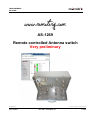
1
m crob t USER MANUAL AS-1269 AS-1269 Remote controlled Antenna switch Very preliminary Microbit 2.0 AB 2010. All rights reserved Ba-AS1269-PA16 a User manual Rev. PA1 – 2013 March 19 1 of 48 m crob t USER MANUAL AS-1269 Table of contents Statement of Conditions .............................................................................. 4 General Description ..................................................................................... 5 Step by step AS-1269 setup ........................................................................ 6 Hardware .................................................................................................... 8 Bottom ......................................................................................................... 8 Top ( under the top cover) ............................................................................. 9 Configuration with Microbit Setup Manager .............................................. 12 FW/HW ....................................................................................................... 13 FW update................................................................................................... 14 Setup ......................................................................................................... 15 Net info....................................................................................................... 16 Initial IP setup .......................................................................................... 17 Configuration with WEB-interface ............................................................. 21 Configuration with WEB-interface ............................................................. 21 Set Antennas ............................................................................................... 23 Inputs......................................................................................................... 23 Temperature/RH .......................................................................................... 24 IP Settings .................................................................................................. 26 Antenna settings .......................................................................................... 29 Serial Settings ............................................................................................. 30 Advanced settings ........................................................................................ 31 Dynamic DNS setting .................................................................................... 33 Remoterig dynamic dns service ...................................................................... 34 DynDNS dynamic DNSservice ........................................................................ 36 Ping Settings ............................................................................................... 38 Radio RRC Settings....................................................................................... 39 Antenna selection ......................................................................................... 40 Application firmware upgrade ........................................................................ 42 Bootloader firmware upgrade ......................................................................... 43 Restart device.............................................................................................. 43 Networks and Firewalls ............................................................................. 43 Portforwarding ............................................................................................. 44 Appendix D - Technical Data ..................................................................... 45 Appendix E - Safety and Regulatory Information ...................................... 46 Microbit 2.0 AB 2010. All rights reserved Ba-AS1269-PA16 a User manual Rev. PA1 – 2013 March 19 2 of 48 m crob t USER MANUAL AS-1269 FCC Statement ............................................................................................ 46 Safety Notice ............................................................................................... 46 Disclaimer ................................................................................................... 47 FCC / CE - Declaration of conformity............................................................... 47 Microbit 2.0 AB 2010. All rights reserved Ba-AS1269-PA16 a User manual Rev. PA1 – 2013 March 19 3 of 48 m crob t USER MANUAL AS-1269 Statement of Conditions In the interest of improving internal design, operational function, and/or reliability, Microbit 2.0 AB reserves the right to make changes to the product described in this document without notice. Microbit does not assume any liability that may occur due to the use or application of the product(s) or circuit layout(s) described herein. All parts of the software are property of Microbit 2.0 AB. The hardware design, schematics PCB layout, concept, graphics, user manual, etc. are property of Microbit 2.0 AB. The device may not be disassembled, copied or reversed engineered. Copyright © 2010,2011 Microbit 2.0 AB All rights reserved. Microbit 2.0 AB 2010. All rights reserved Ba-AS1269-PA16 a User manual Rev. PA1 – 2013 March 19 4 of 48 m crob t USER MANUAL AS-1269 General Description The Antenna switch is designed specially to be used for remote (over the Internet) controlled systems, but can of course be used in other applications also. The switch can be manually controlled via an internal web interface. The switch is connected to the Internet primarily via 10 or 100 Mbit Ethernet and fixed connections like DSL, cable and WLAN or 3G Mobile systems. The Switch is easily configured via modern USB and WEB based user interfaces. Together with Remoterig RRC-1258 it can be setup to automatically follow your band changes. The switch connects to the RRC over IP, no serial port is needed. It can be powered with 48V via the Ethernet cable according to the PoE standard or with 12 DC. This means that the switch can be placed in a tower up to 100m from the schack. The switch is built in stainless steel and can be placed outdoor. It’s normally delivered with SO-239 connectors, but can be ordered with N-connectors, both with PTFE dielectric. Microbit 2.0 AB 2010. All rights reserved Ba-AS1269-PA16 a User manual Rev. PA1 – 2013 March 19 5 of 48 m crob t USER MANUAL AS-1269 Step by step AS-1269 setup Below follows a recommendation about how to proceed when setting up the system. 1. Spend some time to read thru this user manual to get familiar with the product. 2. Remove the top cover of your Antenna Switch. 3. Check that the Jumper JMPx is in the EXT position. 4. Apply 12V DC (good stabilized power) to the unit, either via the 2.1/5,5 DC-jack or via the screw terminals, (see hardware chapter) 5. Connect the unit with a CAT5 patch cables to the same Ethernet switch or router as your PC which you will use to setup the system is connected. Do not bother with the cables through the inlet in the bottom of the Antenna switch until you have set it up and tested that you can control it via the webbrowser. 6. Download the Microbit Setup Manager and the latest firmware from http://www.remoterig.com to your PC. Follow the instructions about how to install the Microbit Setup Manager (see chapter Configuration with Microbit Setup Manager). 7. Find out how your network is configured and configure the AS-1269 to fit into your network (see chapter Initial IP Setup) with the Microbit Setup Manager. 8. Check the installed firmware version. If the one you downloaded from Remoterig is newer, update the unit with the new firmware. (see chapter FW/HW about how to update). 9. When you have configured the unit to fit into your network, Start your Web browser and connect to the unit by entering the IP-address. If you get in contact with the internal web server everything is OK. 10. Make the basic software configuration for your system which is described the later in this user manual. 11. Nov you have to decide how you should use the switch. If you should power it via 12V DC or via Power over Ethernet. If you will use PoE you can disconnect your 12V source and move JMPx on the 1269B pcb to the PoE positon. Connect your LAN cable either to the RJ45 jack marked LAN or to the screw terminals on the 1269B PCB. Now you can use the inlet in the bottom of the Switch to make a more permanent installation. The screw terminals are marked with the standard colors of CAT5/6 cables. Be very careful if you use the screw terminals, Interchanging the wire can damage both the Antenna switch and the PoE supply. Microbit do not take any responsibility of damaged units or connected equipment. Microbit 2.0 AB 2010. All rights reserved Ba-AS1269-PA16 a User manual Rev. PA1 – 2013 March 19 6 of 48 m crob t USER MANUAL AS-1269 12. After preparing the cables connect them to the controlled equipment. Connect the power to all equipment. Check with your web browser again that you are in contact with unit and can control the connected equipment. 13. When everything works as it should on your local network it’s time to setup your Internet router so you can reach the unit from the outside world over the Internet. If you already have other equipment that you remote control you can go direct to 14 as you don’t need to use a separate Dynamic DNS service. 14. The first thing is to determine if your Internet Service Provider (ISP) are providing you with a fixed or dynamic IP-address. Fixed IP:s are rare so you probably have a dynamic IP-address if you are not paying extra for a fixed one. A dynamic IP is no problem but you need to use a dynamic DNS service. You can use Remoterigs free dynamic DNS service or a DynDNS account. New DynDNS account are no longer free. For detailed information about Dynamic DNS services see the Dynamic DNS chapters under Configuration with WEB-Interface. 15. Configure the units Dynamic DNS settings (see chapter Dynamic DNS Setting). 16. Now it’s time to configure your remote router. We recommend that you first enable the remote configuring of your router, you may need it later. After that’s done configure port forwarding (see chapter Network and Firewalls). When this is done your remote control unit should be reachable over the Internet. 17. When back at the Control QTH try to browse to the Dynamic DNS address “Own host name” you registered and entered into the remote control unit. You should get in contact with the Antenna Switch internal web server exactly as it was local, remember to use :port number after the dyndns address if you have changed the webserver port from 80 for example http://sm2oan.mine.nu:8000. Enjoy the remote controlling. Microbit 2.0 AB 2010. All rights reserved Ba-AS1269-PA16 a User manual Rev. PA1 – 2013 March 19 7 of 48 m crob t USER MANUAL AS-1269 Hardware Bottom On the bottom side the antenna connectors are located according to the pictures above. The antenna switch is normally delivered with SO-239 jack but can also be ordered with N connectors. The ventilator will prevent moisture to build up in the housing. Microbit 2.0 AB 2010. All rights reserved Ba-AS1269-PA16 a User manual Rev. PA1 – 2013 March 19 8 of 48 m crob t USER MANUAL AS-1269 Top ( under the top cover) To reach the different connectors the top cover have to be removed. The top cover is secured to the bottom by 8 stainless steel M3 screws. Power The Antenna switch can be power in three different ways depending on your installation. If you install it indoor or where power is available you can connect 12V DC power direct to the Antenna Switch, if you install it at the foot of the tower for example, Power Over Ethernet can be handy to use. 1. Via the 2.1/5.5 DC jack on the 1216H pcb (see picture). In this case the JMP should be in the Ext Pwr position. Microbit 2.0 AB 2010. All rights reserved Ba-AS1269-PA16 a User manual Rev. PA1 – 2013 March 19 9 of 48 m crob t USER MANUAL AS-1269 12V DC Pin no PWR + - + 12-15VDC (centre) GND 2. Via the screw terminals on the 1269B pcb (see pictures). In this case the JMP should be in the Ext Pwr position. The terminals are marked with + and - . 3. Via 48V Power over Ethernet. In this case the JMP should be in the PoE position. You can use a separate PoE Power Injector or use a switch with PoE output. In both cases the power should be applied to the terminals according to the info below. The RJ45 LAN jack is handy to use when setting up the system, while the screw terminals are recommended for permanent installation. If you use the RJ45 for permanent use remember to connect the screen to the screw terminal marked Shield Pin no Screw term Ethernet (RJ45) 1 2 3 4 5 6 7 8 White/Orange Orange Orange/Green Blue Blue /White Green Brown/White Brown Out [+] Out [-] In [+] + 48V DC + 48V DC In [-] - 48V DC - 48V DC USB The USB-interface is used to initially set up the IP parameters. It can also be used for downloading new software (can also be done via the WEB-interface). A USB-cable is included with the product. ETHERNET Microbit 2.0 AB 2010. All rights reserved Ba-AS1269-PA16 a User manual Rev. PA1 – 2013 March 19 10 of 48 m crob t USER MANUAL AS-1269 The unit can be connected to both 10 and 100 Mbit/s Ethernet based TCP/IP network. The Antenna Switch can be configured for different connection types for Ethernet port, Auto, 10HDX, 10FDX, 100HDX, 100FDX and Auto-with-preferred-10FDX. Default is Auto-withpreferred-10FDX which works best in most cases. The Ethernet cable can be connected via the RJ45 LAN jack or via the screw terminals as described under PoE above. ON LED A Green flashing LED beside the USB connector on the 1216H pcb is indicating normal status. STATUS LED A Green flashing LED on the 1269B pcb indicates that the communication between the both pcbs are OK. It will flash fast until the connection is up, and when everything is OK it changes to slow flashing (1per/sec). LINK LED A yellow LED besides the Ethernet connector on the 1216H pcb indicates the status of the Ethernet interface LNK Yellow LED indicates link OK, flashing LED indicates traffic Microbit 2.0 AB 2010. All rights reserved Ba-AS1269-PA16 a User manual Rev. PA1 – 2013 March 19 11 of 48 m crob t USER MANUAL AS-1269 Configuration with Microbit Setup Manager The initial settings of the network parameters are easiest done with the Microbit Setup Manager. The Setup Manager is a software which runs under Windows on a PC and connects to the RC via USB (an USB cable is supplied with the AS-1269).The Setup Manager can be used for: IP Settings and verification o IP-address o Netmask o Gateway o DNS o DHCP Firmware upgrade o Application o Bootloader o Factory default reset Start with downloading the Microbit Setup Manager from the homepage www.remoterig.com. Install the Setup Manager by following the instructions which shows up. If you have an older Windows version where Netframework 2.0 is not installed, the installer will guide you through the installation of Netframework. When you have finished the installation a new shortcut to Microbit Setup Manager will show up on the desktop. Click on the icon to start Microbit Setup Manager Connect your AS1269 to 12V and connect the USB-cable between your computer and the USB jack on the 1216H pcb. Windows will automatically install the necessary drivers. When it's done the text in the bottom field will change from "1216 not connected" to "1216-connected" which is an indication that you are in connection with the unit. Microbit 2.0 AB 2010. All rights reserved Ba-AS1269-PA16 a User manual Rev. PA1 – 2013 March 19 12 of 48 m crob t USER MANUAL AS-1269 FW/HW Click on the "Get" button and the version of the firmware will show up in the upper window. Go to the page www.remoterig.com and under downloads you can find the latest firmware. If there is a newer firmware available download it to your desktop, unzip it. Change to the "FW-update" tab. Microbit 2.0 AB 2010. All rights reserved Ba-AS1269-PA16 a User manual Rev. PA1 – 2013 March 19 13 of 48 m crob t USER MANUAL AS-1269 FW update Click on the "Select file" button and browse to the file with the new firmware, it should be something like “1216H-CRC_v1.23_2011-10-04.bin” depending on the version and release date. When you have selected the file click on the "Update" button and the update process will start, the text in the bottom field will change to "Updating firmware". Attention -- Do not interrupt the update process in any way! After about a 1 minute the update is finished and the Antenna Switch will restart. When the text "RC-connected" shows up again in the lower field of the Microbit Setup Manager, you can change to the "FW/HW" tab and check software version. Microbit 2.0 AB 2010. All rights reserved Ba-AS1269-PA16 a User manual Rev. PA1 – 2013 March 19 14 of 48 m crob t USER MANUAL AS-1269 Setup A new window wills pop-up with the basic IP settings. Change the settings so they fit into your local network and press the "Save" button to save the new settings. The RC will restart again and when the text "1216-connected" shows up again in the lower field of the Setup-Manager, you can click on the "Setup" button again to verify the changes. Microbit 2.0 AB 2010. All rights reserved Ba-AS1269-PA16 a User manual Rev. PA1 – 2013 March 19 15 of 48 m crob t USER MANUAL AS-1269 Net info Click on the “Get” button to read the IP setting currently in use by the Switch. Microbit 2.0 AB 2010. All rights reserved Ba-AS1269-PA16 a User manual Rev. PA1 – 2013 March 19 16 of 48 m crob t USER MANUAL AS-1269 Initial IP setup The default Ip settings from the factory is 192.168.0.236. The net mask is 255.255.255.0, gateway and DNS is 192.168.0.1. To be able to contact the AS-1269 via the network you must configure the units to fit into your home network. You can check your network configuration from your PC. On the start menu select Run. In the Run dialog box enter cmd. You will get a DOS-window. At the DOS-promt enter ipconfig. Then you will get the needed information: Microbit 2.0 AB 2010. All rights reserved Ba-AS1269-PA16 a User manual Rev. PA1 – 2013 March 19 17 of 48 m crob t USER MANUAL AS-1269 Your PC IP address in this example is 192.168.0.101 this means that the IP of the AS-1269 must have IP:s in the area 192.168.0.2 to 192.168.0.255. The Netmask is 255.255.255.0 the Netmask in the RC-1216H should be the same The Default gateway 192.168.0.1 the Gateway and DNS server(*) in the RC should be the same In this case all the default IP setting will be OK. (*) In most cases the Gateway and the DNS server is the same and the IP of the router. Microbit 2.0 AB 2010. All rights reserved Ba-AS1269-PA16 a User manual Rev. PA1 – 2013 March 19 18 of 48 m crob t USER MANUAL AS-1269 In another network, this is the result of the ipconfig command. Your PC IP address in this example is 192.168.128.10 this means that the IP of the AS-1269 must have IP:s in the area 192.168.128.2 to 192.168.128.255. The Netmask is 255.255.128.0 this the Netmask in the RC should be the same The Default gateway is 192.168.128.1 the Gateway in the AS-1269 should be the same In this case you must change the IP:s of the RC. Use the Microbit Setup Manager to change the IP settings. Select the Setup tab click on the “Get Setup” button and enter the IP addresses in the Setup info dialog box. Microbit 2.0 AB 2010. All rights reserved Ba-AS1269-PA16 a User manual Rev. PA1 – 2013 March 19 19 of 48 m crob t USER MANUAL AS-1269 Microbit 2.0 AB 2010. All rights reserved Ba-AS1269-PA16 a User manual Rev. PA1 – 2013 March 19 20 of 48 m crob t USER MANUAL AS-1269 Configuration with WEB-interface Before you can use your Antenna switch AS-1269 you must configure it. The unit will have the default IP addresses 192.168.0.236. The net mask is 255.255.255.0. The configuration is easiest done via the web interface. Be aware of that your PC must be in the same net e.g. having an IP-number between 192.168.0.2 and 192.168.0.254 and not be the same as the AS-1269. If the default IP-address the RC not fit your network please use the PC-program Microbit Setup Manager to change the IP-addresses via USB. Select setup page from the links on the left side and edit the parameters. After each setup pages is finished press Submit to temporary store the new settings. When you do that a new red Apply changes button appears on the pages. You can now change parameters on other pages but the new settings will not take effect until you press Apply changes. When you do that the unit will reboot and start up with the new settings. If you change your mind after clicking on submit you can click on Restart device on the left to restart the device without changing any settings. Microbit 2.0 AB 2010. All rights reserved Ba-AS1269-PA16 a User manual Rev. PA1 – 2013 March 19 21 of 48 m crob t USER MANUAL AS-1269 The info page shows some static information about the Antenna switch as firmware revision etc. and also the basic IP-configuration. Microbit 2.0 AB 2010. All rights reserved Ba-AS1269-PA16 a User manual Rev. PA1 – 2013 March 19 22 of 48 m crob t USER MANUAL AS-1269 Set Antennas The Set Antenna page is the page you use for manual antenna selections. If you have connected the switch a radio for automatic switching you first have to disable the automatic selection with the OFF button on the bottom line. Inputs If you have connected the input to some sensor, you can se the status of the two inputs on this page. High is indicating a open input. Microbit 2.0 AB 2010. All rights reserved Ba-AS1269-PA16 a User manual Rev. PA1 – 2013 March 19 23 of 48 m crob t USER MANUAL AS-1269 Temperature/RH A 1-wire temp or/and humidity sensor can be connected to Bus B, If it’s connected you can see the readings on this page Microbit 2.0 AB 2010. All rights reserved Ba-AS1269-PA16 a User manual Rev. PA1 – 2013 March 19 24 of 48 m crob t USER MANUAL AS-1269 Microbit 2.0 AB 2010. All rights reserved Ba-AS1269-PA16 a User manual Rev. PA1 – 2013 March 19 25 of 48 m crob t USER MANUAL AS-1269 IP Settings The IP Settings menu is used to setup the initial IP parameters needed for the unit to connect to the IP network. Down below the settings are described more in details. Microbit 2.0 AB 2010. All rights reserved Ba-AS1269-PA16 a User manual Rev. PA1 – 2013 March 19 26 of 48 m crob t USER MANUAL AS-1269 Parameter Setting Unit ID (Banner) Text, whatever you want, that will be shown at the top of the web-page (within brackets). Used to identify different units. “empty” (default) “text” Select between a fixed IP address and DHCP. Fixed IP address is recommended. No (default) Yes IP-address (only when fixed IP-address is used) 192.168.0.236 (default) nnn.nnn.nnn.nnn Net mask (only when fixed IP-address is used) 255.255.255.0 (default) nnn.nnn.nnn.nnn Gateway (only when fixed IP-address is used) 192.168.0.1 (default) nnn.nnn.nnn.nnn DNS-address (only when fixed IP-address is used) 192.168.0.1 (default) nnn.nnn.nnn.nnn Sets the port number for the Internal webserver. This port number often has to be changed if port 80 already is used by other equipment. 80 (default) Type of Ethernet connection: Auto Auto, prefer 10 Mbit (default) 10HDX* 10FDX* 100HDX* 100FDX* DHCP IP Netmask Gateway Dns server Web server port Eth-type Auto prefer 10 Mbit is default as more speed is not needed and the emissions from a 10 Mbit LAN is much less than from a 100 Mbit LAN (*) If you use fixed settings you must have a managed switch where you can set the same setting. Microbit 2.0 AB 2010. All rights reserved Ba-AS1269-PA16 a User manual Rev. PA1 – 2013 March 19 27 of 48 m crob t USER MANUAL AS-1269 Web page user Web page pwd Enable password protection for the web by entering a username (this field) and a password (next field). If this field is empty the RC will not ask for password. Some of the pages are still accessible but no editing is possible. “empty” (default) “username” Password for the web pages and telnet connection. “empty” (default) “password” Microbit 2.0 AB 2010. All rights reserved Ba-AS1269-PA16 a User manual Rev. PA1 – 2013 March 19 28 of 48 m crob t USER MANUAL AS-1269 Antenna settings At the Antenna settings page you can enter a text string which describe the antenna you have connected to the antenna ports. Microbit 2.0 AB 2010. All rights reserved Ba-AS1269-PA16 a User manual Rev. PA1 – 2013 March 19 29 of 48 m crob t USER MANUAL AS-1269 Serial Settings The Antenna switch can talk direct to a radio CAT port also if the serial adapter 1216R is connected to the pin header P1. The serial parameters are set on the Serial page. This settings has no effect when you have connected the Antenna switch to the RRC over IP Microbit 2.0 AB 2010. All rights reserved Ba-AS1269-PA16 a User manual Rev. PA1 – 2013 March 19 30 of 48 m crob t USER MANUAL AS-1269 Advanced settings On the Advanced settings page you have to select which protocol you will use depending on your radio. You can select some modes which only listen and do not send any questions. Elecraft K3 uses the Yeasu settings. This setting are used both for control via the serial port and over IP. Microbit 2.0 AB 2010. All rights reserved Ba-AS1269-PA16 a User manual Rev. PA1 – 2013 March 19 31 of 48 m crob t USER MANUAL AS-1269 When connection to a ICOM radio you must know the CI-V Address (hex) the radio are set to. In the example below the switch is connected to a rig with CI-V address 66. The Contr. Address sets the CI-V address of the antenna switch it self. If you have more than one equipment which is a “controller” you may have to change the address to a different one. Microbit 2.0 AB 2010. All rights reserved Ba-AS1269-PA16 a User manual Rev. PA1 – 2013 March 19 32 of 48 m crob t USER MANUAL AS-1269 Dynamic DNS setting The Antenna Switch has a Dynamic DNS client to be used when the Internet Service Provider (ISP) uses dynamic IP addresses instead of fixed IP address. The AS-1269 supports our own free Remoterig dynamic DNS service and DynDNS which is not free for new users anymore. You can choose to use one of them. The Dynamic DNS client checks what IP address your router has got from the ISP and sends the information to the Dynamic DNS:s service DNS server. When using Dynamic DNS you enter "Own host name" instead of an IP address in the web browser and you don't need to bother if the IP address at the Remote site changes. If you already have a Dynamic DNS account registered for any equipment connected to the same router at the remote site, you do not need to register any specific for the AS1269. Microbit 2.0 AB 2010. All rights reserved Ba-AS1269-PA16 a User manual Rev. PA1 – 2013 March 19 33 of 48 m crob t USER MANUAL AS-1269 Remoterig dynamic dns service The Remoterig dynamic dns service only support equipment from Remoterig and Microbit like this Antenna switch, the RC-1216H, the RRC-1258 and the WebSwitch 1216H etc. The Remoterig dynamic dns service do not need any registration it’s automatically generated based on the serial number on the equipment. To activate the Remoterig dynamic dns client select “ddns.remoterig.com” from the drop down on the Dynamic DNS settings page. Also select a DNS check interval, if your IP address change often you can select a low value, if it goes month between the changes you can select a higher value. After that click on “Submit” and “Apply changes”, the RRC will restart. Microbit 2.0 AB 2010. All rights reserved Ba-AS1269-PA16 a User manual Rev. PA1 – 2013 March 19 34 of 48 m crob t USER MANUAL AS-1269 After the switch has restarted go back to the Dynamic DNS settings page. You will now see that the settings Own hostname, Username and Password are automatically generated. The only important information is the Own host name, copy the whole row, this is the information you should put into your web browsers address field when you contact the unit in the future. Store it as a Bookmark as it is difficult to remember. No more registration is needed. Remember that DNS address like this is only for use when you connect over the internet, as long as you are operating on you own LAN use the IP address. Microbit 2.0 AB 2010. All rights reserved Ba-AS1269-PA16 a User manual Rev. PA1 – 2013 March 19 35 of 48 m crob t USER MANUAL AS-1269 DynDNS dynamic DNSservice The Antenna Switch also supports the commercial dynamic DNS service DynDns. Earlier this was a free service, it’s still free for old users but not for new. If your router has a DynDNS client you can also use that one, and do not activate more than one DynDNS client at the same LAN segment. DynDNS do not accept multiple updates from same IP. The DynDNS client checks what IP address your router has got from the ISP and sends the information to DynDNS:s DNS server. When using DynDNS you enter "Own host name" instead of an IP address in we browsers address field and you don't need to bother if the IP address at the remote QTH changes. You need to register an account at http://www.dyndns.com/services/dns/dyndns/ and get a domain name. There are other providers of the same service but AS-1269 only supports DynDNS or Remoterig ddns. Microbit 2.0 AB 2010. All rights reserved Ba-AS1269-PA16 a User manual Rev. PA1 – 2013 March 19 36 of 48 m crob t USER MANUAL AS-1269 Parameter Setting Dynamic DNS check interval Sets how often the external IP address of your router should be checked, value in minutes: Dynamic DNS host name Own host name Username Password Off (Dynamic DNS client disabled) 10 20 30 40 50 60 180 600 1440 Sets which DNS service you will use ddns.remoterig.com (our own free service) members.dyndns.org (commercial service) Domain name registered at DynDNS.com. Example: my-radio-site.ham-radio-op.net Dynamic DNS account username. Dynamic DNS account password. Microbit 2.0 AB 2010. All rights reserved Ba-AS1269-PA16 a User manual Rev. PA1 – 2013 March 19 37 of 48 m crob t USER MANUAL AS-1269 Ping Settings Microbit 2.0 AB 2010. All rights reserved Ba-AS1269-PA16 a User manual Rev. PA1 – 2013 March 19 38 of 48 m crob t USER MANUAL AS-1269 Radio RRC Settings At the Radio RRC settings page you setup the connection to the Radio-RRC if you want the Antenna switch to talk to the radio via the RRC. Note the RRC must be connected to the radio CAT port via COM2 if it should work. Ip number and port should match the settings in the Radio-RRC. Microbit 2.0 AB 2010. All rights reserved Ba-AS1269-PA16 a User manual Rev. PA1 – 2013 March 19 39 of 48 m crob t USER MANUAL AS-1269 Antenna selection At the antenna selection page you can decide which antenna you want to use at different frequencies. First select which antennas you want to be automatically selected on the bottom line. Then you can enter the frequency ranges in the boxes to the left, ant mark which antenna port you want to be active for each range. Microbit 2.0 AB 2010. All rights reserved Ba-AS1269-PA16 a User manual Rev. PA1 – 2013 March 19 40 of 48 m crob t USER MANUAL AS-1269 If you want the antennas to be deselected eg. grounded, after a while when the radio is switched off and the switch get no answers on frequency requests, you can set a “Disconnect timeout. Microbit 2.0 AB 2010. All rights reserved Ba-AS1269-PA16 a User manual Rev. PA1 – 2013 March 19 41 of 48 m crob t USER MANUAL AS-1269 Application firmware upgrade The application firmware can be updated over the Internet via the web interface when bugs are fixed and/or new functionality is implemented. You don't have to be where the Antenna Switch is located to do the updates. Download the new firmware from www.remoterig.com and save the file on your computer (it has a name like 1216H-CRC_v1.38_2011-09-04.bin). Connect to the Antenna switch and select 'Application-upgrade'. Then click on the 'Browse' button and select the file with the new firmware. After that you click on the 'Upgrade' button and the new firmware will be transferred and saved into the RC. When the firmware is updated the RC will restart. Note -- Do not interrupt the upgrade process in any way. Microbit 2.0 AB 2010. All rights reserved Ba-AS1269-PA16 a User manual Rev. PA1 – 2013 March 19 42 of 48 m crob t USER MANUAL AS-1269 Wait a minute or two then connect to the Antenna switch again and select 'Info' and verify that the Software version is updated. If it looks like its not updated empty the web browser cache, to prevent it from showing an old cached page. The update NEVER fails but the browser is a common problem. Bootloader firmware upgrade This follows the same steps as the application firmware upgrade procedure above. Restart device Restart device can be used if you want to reset and restart the Antenna Switch without saving any changes (before apply changes) or just for ordinary reset. Networks and Firewalls One of the major obstacles when trying to remotely control something is the fact that the Internet Service Provider (ISP) forces us to use dynamic IP addresses. We can never know, from time to time, which IP address our modem / firewall / router has on its outside interface (the IP address you will try to connect to). Most people use NAT routers that translates IP addresses on the inside (your little LAN) to one common IP address on the outside using port conversion. At the remote end the router must be configured so that port 80 (default settings) is directed to the Antenna switch which should have a static IP address. If you have other remote controlled equipment connected to the router port 80 is probably already in use and you need to change the webserver port from 80 to something else. In the example below where we have setup the Linksys router we have used port 8000. You will also need to register the Antenna Switch to DynDNS (www.dyndns.com) so you can use a host name to connect to it regardless of its dynamic IP address (which can change without notice, but rarely does). If you already have a DynDns account registered for any equipment connected to the same router, you do not need to register any specific for the Antenna Switch. The following default IP ports are used (changeable) port number function 80 WEB interface WEB interface are TCP-based. Microbit 2.0 AB 2010. All rights reserved Ba-AS1269-PA16 a User manual Rev. PA1 – 2013 March 19 43 of 48 m crob t USER MANUAL AS-1269 Portforwarding A typical setup screen for activating port forwarding is shown below. There is one row assigned for each port (service) all refereeing to the IP of the Radio-RRC and the RC-1216H at the 5th row. . Microbit 2.0 AB 2010. All rights reserved Ba-AS1269-PA16 a User manual Rev. PA1 – 2013 March 19 44 of 48 m crob t USER MANUAL AS-1269 Appendix D - Technical Data Product/Art no: Antenna Switch AS-1269 Frequency Range: 1,6-55 MHz Characteristic impendance: 50 ohm Outputs:(*1) 10 Inputs: 1 Supply voltage PoE (IEEE802.3af): 48V Supply voltage Local: 12-15V Power consumption PoE: 60 mA Power consumption Local: <200 mA Connectors: PTFE dielectric N or SO-239 SWR (1.8-50 MHz): <1.1:1 Insert loss (1.8-30 MHz): <0.03 dB Insert loss (50 MHz): <0.05 dB Power rating (1.8-30 MHz, SWR <1.3:1) 5kW Power rating (1.8-30 MHz, SWR <2:1) 2.5kW Power rating (1.8-30 MHz, SWR <3:1) 1.5kW Ethernet connection(*2): RJ45 or 10 pos terminal Mast clamps: Stainless Steel 51mm Operating temp: -40 -+60 C Dimensions (WxDxH): 200x155x140mm Weight: 2.1 Kg (*1) All unused antenna outputs are grounded, The RF card control lines are surge protected with Metal Oxide Varistors (*2) The control cable should be shielded (FTP) CAT-5e or better. Microbit 2.0 AB 2010. All rights reserved Ba-AS1269-PA16 a User manual Rev. PA1 – 2013 March 19 45 of 48 m crob t USER MANUAL AS-1269 Appendix E - Safety and Regulatory Information FCC Statement This device complies with Part 15 of the FCC Rules. Operation is subject to the following two conditions: This device may not cause harmful interference. This device must accept any interference received, including interference that may cause undesired operation. This equipment has been tested and found to comply with the limits for a Class B digital device, pursuant to part 15 of the FCC Rules. These limits are designed to provide reasonable protection against harmful interference in a residential installation. This equipment generates, uses, and can radiate radio frequency energy and, if not installed and used in accordance with the instructions, may cause harmful interference to radio communications. However, there is no guarantee that interference will not occur in a particular installation. If this equipment does cause harmful interference to radio or television reception, which can be determined by turning the equipment off and on, the user is encouraged to try to correct the interference by one or more of the following measures: Reorient or relocate the receiving antenna. Increase the separation between the equipment and receiver. Connect the equipment into an outlet on a circuit different from that to which the receiver is connected. Consult the dealer or an experienced radio/TV technician for help. FCC Caution: Any changes or modification not expressly approved by the party responsible for compliance could void the user’s authority to operate the equipment. Safety Notice Do not use this product near water, for example, in a wet basement or near a swimming pool. Avoid using this product during an electrical storm. There may be a remote risk of electric shock from lightning. Warning: Never operate this device with a headset or other audio accessories at high volume levels. Hearing expert’s advice against continuous high volume operation, if you experience a ringing in your ears, reduce the volume level or discontinue use. Never connect a power supply of more than 18 VDC to the power jack. The supply voltage must be between 10 V and 18 V. to prevent damaging the device. Microbit 2.0 AB 2010. All rights reserved Ba-AS1269-PA16 a User manual Rev. PA1 – 2013 March 19 46 of 48 m crob t USER MANUAL AS-1269 Disclaimer The author has written this document to the best of his knowledge, but does not guarantee that the contents will satisfy the desire and expectation of the reader. The author or Microbit takes no responsibility for damage or injuries of any kind that may arise from the use and miss use of the product or information contained. The author do not warrant the accuracy and correctness of the information contained. All brand and names mentioned are trademarks or registered trademarks of their respective holders. FCC / CE - Declaration of conformity Appendix F - Contact Information Support site www.remoterig.com E-mail [email protected] Web site www.microbit.se Phone +46 923 69620 Microbit 2.0 AB 2010. All rights reserved Ba-AS1269-PA16 a User manual Rev. PA1 – 2013 March 19 47 of 48 m crob t USER MANUAL AS-1269 Microbit 2.0 AB 2010. All rights reserved Ba-AS1269-PA16 a User manual Rev. PA1 – 2013 March 19 48 of 48