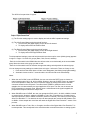
1
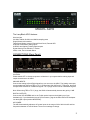
LavryBlack Series
Model AD10
Analog to Digital Converter
Lavry Engineering, Inc.
P.O. Box 4602
Rolling Bay, WA 98061
http://lavryengineering.com
email: [email protected]
Rev 1.20
January 24, 2008
Quick Start Guide
The AD10’s front panel has 3 regions:
(1) The Function setting region is used to display and edit the AD10 operational settings.
(2) The Left Channel Meter region has a dual function
1. A level meter (bar graph display) for the AD10 Left channel.
2. To display and set the Left Channel Gain
(3) The Right Channel Meter region has a dual function
1. A level meter (bar graph display) for the AD10 Right channel.
2. To display and set the Right Channel Gain
To edit operational settings, press and hold the switch lever down until a cursor (blinking lamp) appears
in region 1. Region 1 is made of 4 groups (Rate, Clock, Sound, and Bits).
- Each click of the switch in the DOWN direction will move the cursor horizontally to the next available
group. Move the cursor to the group you wish to edit.
- Each click of the switch in the UP direction changes the setting vertically within the selected group.
You can change as many settings as needed, then exit region 1 edit mode. There are 2 ways to exit:
1. Press and hold the switch down until the cursor disappears (the blinking lamp lights steadily).
2. Automatic timeout: wait for 7 seconds and the unit will exit edit mode automatically.
Notes:
1. When the unit CLOCK is set to INTERNAL, the user can select the RATE group to choose an
internal sample rate of 44.1, 48, 88.2 or 96KHz. However, when the CLOCK is set to an external
clock mode (WORD or AES), the user is required to supply an external word clock to the BNC
connector located on the rear panel. For external clock (WORD or AES) the rate is not user
settable; thus it is determined by the signal applied to clock input. The user can not access the
RATE group when in external mode. Instead, when a valid external clock signal is applied; the
proper RATE lamp will indicate the sample rate.
2. When SOUND is set to CLEAR, the user can operate the AD10 at 44.1, 48. 88.2 or 96KHz, internal
or external clocks. However, setting the SOUND to Tube, Xfrm (Transformer) or Complex sound,
alters the selection to 88.2 or 96KHz conversion (internal or external). This is done to insure Digital
Alias-Free Emulation™. If so desired, the user can later sample rate convert the AD10 data to 44.1
or 48KHz. A later sample rate conversion will retain the Digital Alias-Free Emulation™ nature of the
process.
3. When SOUND is set to Tube, Xfrm, or Complex, the effect of the Digital Alias-Free Emulation™ is
level-dependent. This corresponds to the effect that tubes or transformers have on analog signals-
1
they produce little coloration at low signal levels where they are more “linear,” and increasingly
color the sound as signal level rises. To hear the maximum effect of the coloration in Tube, Xfrm, or
Complex mode, the signal level must be near (but just below) full scale digital level. It is possible to
“clip” the signal in the emulation modes. As in CLEAR mode, clipping is indicated by the “0dB” lamp
illuminating on the AD10 meters.
To Edit Region 2 (Left Channel Gain), press and hold the switch UP until a cursor (blinking lamp)
appears in the Left channel bar graph. The position of the cursor indicates the gain setting using the
scale on the meters without the minus signs. For example, a blinking -6dB lamps means a gain setting
of 6dB.
- Each click of the switch in the UP direction increases the gain by 1 dB.
- Clicking the switch in the DOWN direction reduces the gain by 1dB.
After setting the left channel gain, you can either:
1. Wait 7 seconds for the unit to exit Region 2 (Left channel gain) edit mode
2. Press and hold the switch in the UP direction, until the cursor (blinking lamp) appears on the
Right channel (region 3). The cursor indicates the Right channel gain setting. You can alter
the gain (increase by 1dB by clicking the switch up, decrease the gain by 1dB by clicking the
switch down).
You can exit Region 3 (Right channel gain) edit mode by either:
1. Wait 7 seconds for the unit to exit the edit mode
2. Press and hold the switch in the UP direction, until the cursor disappears (the lamp
stops blinking)
Notes:
1. The AD10 can accommodate either XLR or ¼ inch connectors (balanced or unbalanced
signals in both cases). In the case of ¼” plugs, TRS (Tip-Ring-Sleeve) 3 conductor plugs are
typically used for balanced and TS (Tip-Sleeve) 2 conductor plugs are used for unbalanced
connections. The gain range between 0-13dB applies when using the XLR analog inputs. When
¼” plugs are used, the AD10 automatically adds 13dB of fixed gain to the adjustable gain, to
accommodate the lower level signals typical of ¼” connectors. Synthesizer line outputs, guitar
effects units with line outputs, and smaller mixers with ¼” connections are examples of this type
of signal.
2. The unit is shipped with a meter “PEAK HOLD” function enabled. The Hold keeps the highest
left channel and the highest right channel lamps lit. A quick click of the switch (Up or Down)
clears the “Hold” display and starts a new “search” for maximum levels. The user can disable the
Hold function via internal jumper. Please see the operation manual for more details.
2
MODEL AD10
The LavryBlack AD10 features:
Ultra low jitter
44.1KHz, 48KHz, 88.2KHz and 96KHz sampling rates
Single Switch User interface
Three Clock Modes- Internal, External Word Clock, External AES
XLR/TRS Combination analog inputs
XLR/RCA and Optical (Toslink) digital outputs.
Digital Aliasing-Free Emulation™ modes
24-bit, 16-bit, and 16-bit with Dither
CONNECTIONS (Rear Panel)
CAUTION:
Please switch OFF or disconnect power to all devices in your system before making input and
output connections to the AD10.
ANALOG INPUTS:
Connect the Analog Left and Right Inputs from your source to the AD10. The Analog connectors
accommodate both XLR and TRS or TS ¼” Phone plugs. With XLR and ¼” TRS plugs, the AD10
accepts either balanced or unbalanced signals. TS ¼” plugs can be used for unbalanced signals.
Note: When using TRS or TS ¼” plugs, the AD10 will automatically increase the gain by 13dB.
DIGITAL OUTPUTS:
Connect the XLR AES/EBU and /or the Toslink optical output to the digital input of your
destination(s). If your destination has an RCA connector, plug the included XLR to RCA adapter
into the digital output (marked AES/SPDIF).
AC POWER:
The AD10 automatically adjusts to AC power inputs in the range of 90 to 264 Volts AC and line
frequencies between 47 and 63 Hertz. There are no settings to change.
3
OPERATION:
A. Overview
The AD10 has a single User Interface Switch that allows all functions to be controlled
from one place. Moving the switch up or down will either select or set the function. All
Rate, Clock, Sound, Bit Depth and Gain Control functions are controlled by this switch.
When powered on, the unit initializes for about 6 seconds. After initialization completes,
the function lamps indicate the unit settings. Also, the Level and Gain meters will flash for
about 6 seconds to indicate the Gain setting for each channel. The unit is ready for use
when the meters stop flashing.
B. Functions
In normal operating mode, one LED will be lit for each function, indicating the setting for
that function. While in editing mode, a flashing LED will indicate status and function
during programming. To enter the Function Mode, press the switch DOWN and hold it in
this position until a Function LED starts to flash. Release the switch.
Either click the switch DOWN to select the next function (Sample Rate, Clock, Sound, or
Bit Depth), or click the switch UP, to select the next available Setting within that function.
Please Note- To move more than one step, the switch must be clicked repeatedly;
holding the switch down (or up) will not result in the setting changing by more than one
step. It will either only change one step, or if held long enough in the applicable direction,
will change the mode.
To exit Function editing mode, hold the switch DOWN until the LED stops flashing.
Alternatively, wait for 6 second (leave the switch untouched) and the unit will
automatically exit the editing mode.
C. Gain
In normal mode the Level Meter indicate signal from 0dB, or Full Scale, to -13dB digital
level. In Gain Mode, this meter will allow you to set up to 13dB’s of gain, with each
channel being individually controlled. When in Gain Set mode, ignore the minus sign in
front of each of the Level values on the meter scale; these values will indicate the amount
of Gain you are setting.
Please Note- If an input signal is present; the signal level will be displayed in the Gain Set
mode at the same time as the Gain setting, so you can see the effect of the gain
adjustment on the signal while you are changing it. You may want to mute the input to
see the gain indication by itself, especially when you are using the AD10 for the first time.
To Enter the Gain Mode, press and hold the switch in its UP position until one of the Left
Gain LED’s starts to flash, indicating the amount of gain selected for that channel. Click
the switch up or down to either increase or decrease the amount of gain. With each
successive switch click, the gain is changed by 1 dB.
After setting the Left channel, you can adjust the RIGHT channel by holding the switch in
the UP position until one of the Right Gain LED’s starts to flash, indicating the gain
selected for the Right channel. Click the switch up or down to either increase or decrease
the amount of gain. With each successive switch click, the gain is changed by 1 dB.
To exit Gain Mode, hold the Switch in the UP position until the LED stops flashing.
Alternatively, wait for 6 second (leave the switch untouched) and the unit will
automatically exit the editing mode.
Note:
The input connectors can accept either Balanced or Unbalanced signals. When using TRS or TS
¼” plugs, the unit will automatically increase the gain by 13dB’s in addition to the adjustable gain.
4
Function Description
A. Internal Clock Operation
The LavryBlack AD10 operates on Internal Clock at one of four standard sample rates44.1KHz, 48KHz, 88.2KHz and 96KHz. The Sample Rates are user selectable (please
see the Functions section under the OPERATION heading for details).
B. External Clock Operation
The AD10 can be synced to an external clock via the BNC connector on the back panel.
This input will accept either Word Clock or AES signals. When the External Clock
function is selected, the AD10 will lock an external frequency between 32KHz and
100KHz. In External Clock mode (Word or AES setting), it is not possible to set the
Sample Rate Function, because the AD10 automatically detects the incoming signal
frequency. The Rate lamps are used to indicate the external clock frequency, and to
indicate that the AD10 is locked to the external sync.
In External Clock operation, the Sample Rate indicators function as follows:
The 44.1 KHz lamp indicates an external clock rate between 32KHZ and 46KHz
The 48.0 KHz lamp indicates an external clock rate between 46KHZ and 68KHz
The 88.2 KHz lamp indicates an external clock rate between 68KHZ and 92KHz
The 96.0 KHz lamp indicates an external clock rate between 92KHZ and 100KHz
C. Digital Alias-Free Emulation™
The LavryBlack AD10 offers three Digital Alias-Free Emulation™ modes: tube,
transformer, and complex (both tube and transformer). Sound coloration due to
distortions of analog components generates many higher frequency harmonics. With
analog gear, the ear responds to audible energy and it does not respond to the high
frequencies above audibility.
With digital processing there is a more serious effect; these supersonic high frequencies
alias back into the audible range at frequencies that are not musically related, thus
creating an unmusical and harsh distortion. The proprietary Digital Alias-Free
Emulation™ process allows users to add accurate coloration without the unwanted alias
distortions.
The design of the emulations requires use of a higher sampling rate; either 88.2KHz or
96KHz. When selecting Tube, Xfrm, or Complex coloration, the unit will operate at double
speed (88.2 or 96KHz). A unit set to single speed will automatically double the rate when
set to one of the digital emulation modes. If set to external clock (Word or AES), the unit
will lock to 88.2 or 96KHz, and will not lock to 44.1 or 48KHz external clock. Lock is
confirmed by the appropriate sample rate indicator illuminating.
The user can later convert the digital audio to single speed (44.1 or 48KHz) by use of a
hardware or software sample rate converter (SRC). Such later conversion retains the
advantage of alias-free distortions.
D. Bit Depth
The Bit Depth can be set to 24 bit, 16 bit, or 16 bit plus Dither (16+D).
A Bit Depth setting of 24 bit offers the widest dynamic range, while settings of 16 bit or
16 bit plus Dither offer smaller dynamic ranges. 24 bits is recommended for most cases.
16 bit plus Dither is aimed at recording material intended for making a CD where no
further processing will take place.
5
E. Peak Hold
The AD10 is set in the factory with the Peak Hold activated. The user may disable the
Peak Hold function by moving the internal jumper U34 from the ON to the OFF position.
When set to the ON position the Level meter will always indicate Peak levels by keeping
the highest LED for each channel on.
To clear the Peak Hold indication, click the Programming switch up or down momentarily.
This resets the Peak Hold, and it will move to the newest peak level.
F. Avoiding Clicks
The AD10 provides protection against its own “power ON clicks”.
The AD10 CANNOT protect against “power ON clicks or pops” from analog sources
feeding the AD10. ALWAYS apply power to analog sources connected to the AD10
before powering the AD10.
Switching between Sample Rates, Bit and clock modes (Internal, Word, or AES) during
operation may cause unwanted clicks, especially when the signal is loud.
It is advised that when switching Functions that no signal level be present, if possible,
and that the monitor speaker volume is low.
G. External Clock input termination
The AD10 factory setting for the BNC connector input termination impedance is 75
Ohms. That connection calls for 75 Ohm cables typical of Word Clock connections. The
unit can be set to accommodate 110 Ohms cables typical of AES connections by
changing the internal jumper U11 setting from 75 to 110, and using the appropriate
adapter for the BNC connection. U11 is located near the rear panel.
6
SPECIFICATIONS:
THD+N at Maximum Gain – less than .001% FS
(Test conditions: 20Hz – 20KHz, -3dBFS sine wave, 22-22KHz BW, 24 Bit, Clock=internal,
Color=Clean, Bits=24)
Dynamic Range: - better then 117dB (non-weighted), better then 120dB (A-Weighted)
Maximum Input level to achieve “0dB Full Scale” digital level (Analog levels + 0.25 dB):
XLR Balanced input:
With gain set to 0 dB
With gain set to 13 dB
+24dBu
+11dBu
XLR Unbalanced input:
With gain set to 6 dB
+18dBu
With gain set to 13 dB +11dBu
¼” input Balanced or Unbalanced:
With gain set to 0 dB
+11dBu (+8.8dBV)
With gain set to 13 dB - 2dBu ( -4.2dBV)
Input connections:
XLR
- Balanced analog: Pin 2 non-inverting, Pin 3 Inverting. Pin 1 shield
- Unbalanced analog: Pin 2 non-inverting, Pin 3 signal return, Pin 1 shield
¼”
- Balanced analog TRS: Tip non-inverting, Ring inverting, Sleeve shield
- Unbalanced analog TS: Tip non-inverting, Sleeve signal return and shield
BNC
- Termination set to 75 Ohms for Word Clock or AES connections using standard 75 Ohm
coaxial cable with BNC connectors. Termination can be set by user to 110 Ohms using
internal jumper U11 for AES signals connected using 110 Ohm cable with a BNC
adapter.
Digital Output Connections:
XLR
- Connect to AES inputs using standard 110 ohm XLR to XLR cables
- Connect to coaxial SPDIF inputs using supplied XLR to RCA adapter and user supplied
75 Ohm RCA to RCA “SPDIF” cable or user supplied adapter cable. 75 Ohm coaxial
cable length should be kept short if possible- less than 3 meters; 2 meters is better and 1
meter is best.
Optical - Optical output connects to SPDIF optical inputs using standard Toslink interconnect.
AC Power:
Voltage 90-264 VAC, Frequency 40-63Hz, Current 0.1A
Fuse Rating 4A “Fast Blow” *
*Subject to change! Please always check the rating on the fuse and the one printed next to the
fuse holder on the power supply PC board before replacement. Replace the fuse ONLY with a
fuse of the same rating. If you have any questions, contact: [email protected]
7
ACCESSORIES
Included in box: U.S.A. Power Cord, XLR to RCA Adapter, Warranty Card, This User’s Manual
Optional: LavryBlack Series 19 inch rack-mount kit
This kit is designed to mount two LavryBlack units side-by-side in a 1U rack space.
8
LIMITED WARRANTY – LAVRYBLACK SERIES MODEL AD10
Subject to the conditions set forth below, for one year after the original purchase date of the
product, Lavry Engineering will repair the product free of charge in the United States in the event
of a defect in materials or workmanship.
Lavry Engineering may exchange new or rebuilt parts for defective parts. Please call the factory
for an RMA number prior to shipment. No product will be accepted for warranty service without
a pre-issued RMA number.
This warranty is extended only to an original purchaser of the product from Lavry Engineering, or
an authorized reseller of Lavry Engineering. Products that are purchased from unauthorized
resellers do not have any warranty coverage. A valid purchase receipt or other valid proof of
purchase will be required before warranty service is provided. This warranty only covers failures
due to defects in materials or workmanship and does not cover damages which occur in shipment
or failures resulting from accident, misuse, line power surges, mishandling, maintenance,
alterations and modifications of the product, or service by an unauthorized service center or
personnel. Lavry Engineering reserves the right to deny warranty service to products that have
been used in rental, service bureau, or similar businesses.
This limited warranty gives you specific legal rights. You may have others which vary from
state/jurisdiction to state/jurisdiction.
LIMITS AND EXCLUSIONS
LAVRY ENGINEERING DOES NOT, BY VIRTUE OF THIS AGREEMENT, OR BY ANY
COURSE OF PERFORMANCE, COURSE OF DEALING, OR USAGE OF TRADE, MAKE
ANY OTHER WARRANTIES, EXPRESS OR IMPLIED, INCLUDING, WITHOUT
LIMITATION, ANY WARRANTY OF MERCHANTABILITY, FITNESS FOR A
PARTICULAR PURPOSE, TITLE OR NONINFRINGEMENT, AND ALL SUCH
WARRANTIES ARE HEREBY EXPRESSLY DISCLAIMED. LAVRY ENGINEERING
EXPRESSLY DISCLAIMS ANY IMPLIED INDEMNITIES. LAVRY ENGINEERING SHALL
NOT BE LIABLE FOR ANY INDIRECT, INCIDENTAL, CONSEQUENTIAL, PUNITIVE,
SPECIAL OR EXEMPLARY LOSSES OR DAMAGES, INCLUDING, WITHOUT
LIMITATION, DAMAGES TO RECORDINGS, TAPES OR DISKS, DAMAGES FOR LOSS
OF BUSINESS PROFITS, BUSINESS INTERRUPTION, LOSS OF BUSINESS
INFORMATION, LOSS OF GOODWILL, COVER, OR OTHER PECUNIARY LOSS,
ARISING OUT OF OR RELATING TO THE USE OF THE PRODUCT, OR ARISING FROM
BREACH OF WARRANTY OR CONTRACT, NEGLIGENCE, OR ANY OTHER LEGAL
THEORY, EVEN IF LAVRY ENGINEERING HAS BEEN ADVISED OF THE POSSIBILITY
OF SUCH LOSSES OR DAMAGES. ANY DAMAGES THAT Lavry ENGINEERING IS
REQUIRED TO PAY FOR ANY PURPOSE WHATSOEVER SHALL NOT EXCEED THE
ORIGINAL COST PAID TO LAVRY ENGINEERING FOR THE APPLICABLE PRODUCT.
BECAUSE SOME STATES/JURISDICTIONS DO NOT ALLOW THE EXCLUSION OR
LIMITATION OF LIABILITY FOR CONSEQUENTIAL OR INCIDENTAL DAMAGES, THE
FOREGOING LIMITATION MAY NOT APPLY TO YOU.
9