1
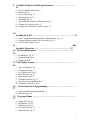
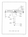
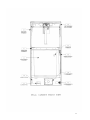
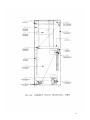
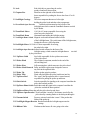
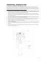
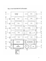
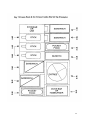
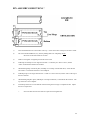
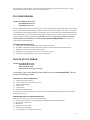
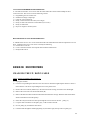
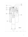
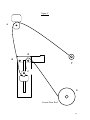
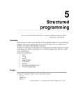
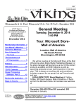
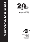
F631 FROZEN MERCHANDISER
F631 FROZEN MERCHANDISER
F631 FROZEN MERCHANDISER
USERS MANUAL FOR:
F631 FROZEN MERCHANDISER
FASTCORP
FOOD AUTOMATION SYSTEMS AND TECHNOLOGIES
One Cory Road
Morris Township, New Jersey 07960 USA
973-455-0400
Version 4
1
CONTENTS
1. The Warranty ………………………………………………………….
5
a. F-631 Warranty Pg. 5
2. Part Views ...…...……………………………………………………….
6
a. Front Door Pg. 6
b. Inside Door Pg. 7
c. Front of Robot Pg. 8
d. Back of Robot Pg. 9
e. Front of Cabinet Pg. 10
f. Side of Cabinet Pg. 11
3. Glossary of Components and Key Terms
…………………………...12
a.
b.
c.
d.
Front View Terms Pg. 12
Back of Door Terms Pg. 12
Robot Components Pg. 12-13
Cabinet Components Pg. 13-14
4. Uncrating Instructions ………………………………………………
15
5. F631 Measurements/Specifications ………………………………...
16
a. Dimensions Pg.16
b. Electrical Requirements Pg. 16
6. Setting Up the F631 Frozen Merchandiser ………………………..
17
a.
b.
c.
d.
Internal Power Supplies Pg.17
Internal Gang Outlet Pg.17
Clearing the Memory Pg.17
Computer Board Option Switches Pg.17
7. Operating Modes ……………………………………...……………...
17
a. Service Mode Pg. 17
b. Free Vend/Test Vend Pg.17
c. Insert Money Pg. 17
d. Vend Block Pg. 17
e. Reset Function Pg. 18
8. Money Systems .….…………………………………………………...
18
a. Micro Mechanism and Appropriate Settings Pg. 18
b. Multi Drop Bus Interface Pg. 18
c. Executive Interface Pg. 18
2
9. Vendible Products and Bin Specifications …………………………
19
a.
b.
c.
d.
e.
f.
g.
h.
List of Vendible Products Pg. 19
Bin Sizes Pg. 20
Freezer Capacity Pg. 21
The Bin System Pg. 21
Bin Lengths Pg. 21
Types/Methods of Product Configurations Pg. 21
Example Ice Cream Set-up Pg. 22
Example Frozen Food/Ice Cream Set-up Pg. 23
10.
Loading the F-631 ………………………………………………….. 24
a. Freezer Temperature/Thermostat/By-Pass Health Sensor Pg. 24
b. Loading Procedures/Open/Close Freezer door Pg. 24
c. How To Stack Product Pg. 24
11.
Bin
Assembly Directions ………………………………………...… 25
12. Freezer Maintenance ………………………………………………
26
a. Frost Build-up Pg. 26
b. Spring Cleaning Pg. 26
c. Meltdowns Pg. 26
13. The Display System ………………………………………………….
26
a.
b.
c.
d.
e.
f.
g.
Types of displays Pg. 26
Necessary Items Pg. 27
F631 Display Pack Pg. 27
Boxed Products Pg. 27
Paper Products Pg. 27
Cellophane Products Pg. 27
Choosing Selection Numbers Pg. 27
h. Mounting Your Product Pg.27
14. An Introduction to Programming ………………………………...
27
a. Getting Started/Creating Selections Pg. 28
b. Menu Items Pg. 28
15. Program Menus …………………………………………………….
29
a.
b.
c.
d.
e.
Change Price Pg. 29
Sales Meters Pg. 29
Edit Selection Pg. 30
Create Selection Pg. 32
Delete Selection Pg. 33
3
f.
g.
h.
i.
j.
k.
l.
m.
n.
o.
p.
q.
r.
Selection #’s Pg. 33
Set Date Pg. 34
Set Time Pg. 34
Set Service Phone Pg. 34
Sales Pin Code Pg. 35
Vend Block/VB Pin Code Pg. 35, 36
Health Timer Pg. 36
Program Version Pg. 37
Display Language Pg. 37
Line Mode Pg. 37
Machine Serial Number Pg. 37
Card Reader Option Pg. 38
Group Sales Option Pg. 38
16. Sequence of Operation ……………………………………………..
39
a. How the Freezer Door Is Opened Pg. 39
b. How the Robot Moves Back Pg. 39
c. How the Robot Moves to the Right Pg. 39
d. How the Picker Head Is Lowered Pg. 39
e. How the Vacuum is Turned On Pg. 40
f. How the Picker Head is Lifted Pg. 40
g. How the Carriage Moves Left Pg. 40
h. How the Robot Comes to the Front Pg. 40
i. How the Robot Drops the Product Pg. 40
17. Self-Diagnostics Feature/Troubleshooting ………………………
41
a.
b.
c.
d.
e.
f.
g.
h.
Bin Errors Pg. 41
Fuses Pg. 41
Adjusting Vacuum Pressure Pg. 41
Encoder Errors Pg. 41
Motor Stuck Errors Pg. 42
Freezer Motor Errors Pg. 42
Vacuum System Error Pg. 42
Health Sensor Error Pg. 43
18. Repair Procedures ………………………………………………….
43
a.
b.
c.
d.
e.
f.
g.
h.
i.
Changing the Up/Down Cable Pg. 43
Changing the Freezer Cable Pg. 46
Removing the Freezer Pg. 48
Replacing the Freezer Pg. 48
Removing the Robot Pg. 49
Replacing the Robot Pg. 49
Replacing the Up/Down Encoder Pg. 49
Replacing the Left/Right Encoder Pg. 50
Replacing the Front/Back Encoder Pg. 50
4
5
THE F631 FROZEN MERCHANDISER
LIMITED WARRANTY
WARRANTY
Subject to the limitations specified herein, FASTCORP warrants the F631 Frozen
Merchandiser (the “F631”) to be free under normal use and service from defects in parts and
workmanship for a period of two (2) years from the date of purchase and the F631’s freezer
system consisting solely of the compressor to be free under normal use and service from defects
in parts and workmanship for a period of five (5) years from the date of purchase. This
warranty is limited to the replacement of any part or parts, free of charge, which Fastcorp
determines to be defective after the defective part is returned with transportation charges
prepaid to the destination designated by Seller's Warranty Department. All labor charges shall
be for the account of customer. The warranties provided herein apply only to the original
operator of the F631 and are null and void if the F631 is sold during the period of warranty.
The limited warranties provided for herein do not apply to: (i) the F631 or any part thereof if
Fastcorp determines that the defect was caused by misuse, abuse, vandalism, improper
application, improper operation, improper maintenance, alteration, repair or modification,
negligence or use, casualty, fire, flood, storage, handling or any other cause beyond the control
of Fastcorp; (ii) electrical components, wiring, or circuits and/or for all mechanical parts or
assemblies damaged as a result of operating the F631 Frozen Merchandiser at other than 115
volts, 60 Hertz current; (iii) incandescent lamps, neon lamps, fluorescent lamps, ballast, starters,
glass or plastic windows or other expendable items; or (iv) accessories used or installed in the
unit which were manufactured by some person or entity other than Fastcorp.
THE WARRANTIES PROVIDED ABOVE ARE EXCLUSIVE AND IN LIEU OF ALL
OTHER WARRANTIES, OBLIGATIONS OR LIABILITIES. FASTCORP EXPRESSLY
DISCLAIMS ALL OTHER WARRANTIES, EXPRESSED OR IMPLIED, INCLUDING
WITHOUT LIMITATION, WARRANTIES OF MERCHANTABILITY OR FITNESS
FOR A PARTICULAR PURPOSE. UNDER NO CIRCUMSTANCES SHALL
FASTCORP BE LIABLE FOR ANY INCIDENTAL, CONSEQUENTIAL OR SPECIAL
DAMAGES, LOSSES OR EXPENSES WHICH ARISE FROM OR IN CONNECTION
WITH THE OPERATION, USE AND/OR INABILITY TO USE THE F631 IN ANY
MANNER.
The warranty contained herein is the exclusive warranty applicable to F631 and no Fastcorp
representative or any other person is authorized to offer or agree to any other warranty or
liability in connection with the F631.
The F631 Frozen Merchandiser adheres to FASTCORP’ s strict standards of engineering excellence, quality,
and reliability. FASTCORP recommends all operators read this manual and adhere to the instructions.
Contact the FASTCORP Warranty Department at (973) 455-0400 with any questions or write to:
FASTCORP
Warranty Department
One Cory Road
Morris Township, NJ 07960 USA
6
7
Figure 2
8
9
10
11
12
GLOSSARY OF COMPONENTS AND KEY TERMS
Figure/Name
Description
The 40 character fluorescent display shows product
information and operation instructions to the customer. The
display also lists menu items and self-diagnostics.
1-2 Bill Validator
Receives, validates, and stores paper currency.
1-3 Coin Return
Metal enclosure which holds any returned coins.
1-4 Coin Return Button
Button on the outside of the door that will clear the
coin mechanism’s rejecter of any damaged coins
and will cancel all credits.
1-5 Coin Slot
Opening where coins are deposited.
1-6 Customer Keypad
External keypad used by customers to select products
and by field personnel for program functions.
1-7 Customer Door
Door below tempered glass for product retrieval.
1-8 Duratrans
Back-lit sign made of film-like material.
1-9 Door Lock
Twist style door locking mechanism.
1-10 Product Displays
Dummy product packages that advertise a selection.
1-11 Product Display Bars Black metal strips that anchor product display holders.
1-12 Product Display Holders
Clear plastic pieces that hold product displays.
1-1 Alpha-Numeric Display
2-1 Bill Validator Blank
2-2 Cash Enclosure Door
Painted metal bill validator cover.
Fully hinged door that prevents access to money from
vandalism or from unauthorized service personnel.
2-3 Coin Box
Storage enclosure for coins.
2-4 Coin Mechanism Mount
Three mounting screws for placement of coin
mechanism.
2-5 Computer Board Logic board responsible for all operations.
2-6 Computer Door
Hinged door protecting computer board.
2-7 Customer Delivery Box Enclosure behind customer door where product
is dispensed.
2-8 Light Fixture
A 20 Watt Fluorescent fixture that holds two 24” t12 bulbs.
2-9 Harnessing
Power cord for light fixture.
2-10 Serial Tag
Machine serial number and other basic information.
2-11 Power Box
Metal box which protects the power board.
2-12 Power Board
Provides 115 VAC and unregulated DC to
money acceptors. Controls all A/C motors and vacuum motor.
There are three fuses and four capacitors on the power board.
(See Fuses)
2-13 Service Switch
Three position switch used to enter service mode.
The switch can be pulled out to simulate closing the door.
2-14 Service Keypad
Internal keypad mounted on the computer door used for
service mode operations.
13
3-1 Axle
Rod which drives gears along the rack to
produce front/back robot motion.
3-2 Capture Bar
Metal bar on the right side of the front/back
beam responsible for pushing the freezer door from 45 to 90
degrees.
3-3 Left/Right Carriage
The robot component that moves left to right
holding the picker head and other robot components.
3-4 Front/Back Opto-Encoder
Infrared switch mounted on the left side of the
left/right beam which counts the Front/Back distance traveled
by the Robot.
3-5 Front/Back Motor
110 Volt A/C motor responsible for moving the
robot forward or backward.
3-6 Front/Back Beam
Horizontal beam holding the left/right carriage.
3-7 Left/Right Home Switch Magnetic reed switch mounted on the left side
of the Left/Right beam. The switch turns off the left/right motor,
locating the robot to a full left position.
3-8 Left/Right Motor 110 Volt A/C motor responsible for moving,
the robot left or right.
3-9 Left/Right Opto-Encoder Infrared switch mounted on the front of the
left/right carriage, which counts the left/right distance traveled
by the picker head.
3-11 Up/Down Cable
Steel cable responsible for the up/down movement
of the picker head.
3-12 Picker Head
The weighted component, attached to the end of the
self-retracting hose.
3-13 Picker Hose
Self-retracting hose which connects to the picker head.
3-14 Picker Slack Removal Pulley and dead weight system designed to remove
any slack in the up/down cable.
3-15 Picker Tip
Rubber tip that grips the product.
3-16 Picker Tube
Plastic tube that guides the picker head down into bin.
3-17 Up/Down Reel
The “spool” that the up/down cable is wound around,
responsible for pulling the picker up and down.
3-18 Slack Switch
Switch responsible for signaling to the computer board that the
picker has touched product.
3-19 Up/Down Home Switch Switch that sends the signal to the computer board that the
picker has reached the home position.
3-20 Up/Down Motor Motor that pulls the picker head up and down.
3-21 Up/Down Opto-Encoder Circuit board that “measures” the distance traveled by the
picker head by counting flashes as the disk spins through it.
3-24 Vacuum Switch
Pressure-activated switch that “senses” if the product has
fallen off the picker tip.
3-25 Left/Right Magnet Bracket Bracket that holds the left/right magnet onto the
carriage
3-26 Ribbon Cable
Flat harness that houses all wires going to the robot.
14
4-2 Bulkhead Plate
Wire junction for all harnesses between the main door
and cabinet.
4-4 Freezer
Seven cubic foot capacity chest freezer.
4-5 Freezer Door
The freezer lid which is opened by the freezer door motor.
4-6 Freezer Door Cable
Steel cable responsible for lifting and
lowering the freezer door.
4-7 Frzr. Door Home Switch Magnetic reed switch mounted on the left side of
the cabinet, that senses the magnet attached to the freezer door.
4-8 Freezer Door Motor
Provides up or down movement of the freezer door.
4-9 Freezer Door Reel
Reel responsible for reeling the freezer cable up and
down.
4-10 Fzr Door Slack Removal Pulley and dead weight system designed to allow
the freezer cable to remain taught.
4-11Freezer Door Up Switch Magnetic reed switch that senses the freezer door
magnet, stopping the door at a 45 degree angle.
4-12 Frt./Back Home Switch Magnetic reed switch that senses the front/back
beam, stopping the carriage in the product drop off area.
N.S. Health Switch
Prevents operation of the machine if the temperature rises
above 15º F, requiring the F631 to be manually reset.
4-14 Power Outlet Box
Main outlet box for all power plugs.
4-15 Safety Stops
Screws at the end of the front/back racks preventing the
robot from coming out of the cabinet.
4-17 Thermometer
NSF approved vapor tension thermometer.
4-18 Thermostat
Temperature controller that can be adjusted
with a standard screwdriver: clockwise to lower the freezer
temperature, or counter-clockwise to raise the temperature.
4-19 Tracks/Racks
Tracks located on the left and right sides of the cabinet that the
robot travels on when moving from front to back.
4-20 Vacuum Box
Provides vacuum for the robot.
15
UNCRATING INSTRUCTIONS
A COPY IS ATTACHED TO THE FRONT GLASS
The F631 Frozen Merchandiser has been crated and packed in order to protect its internal components
during transportation and distribution. FASTCORP has also attempted to make unpacking and installation
a simple and quick process. FASTCORP recommends the following steps be taken when uncrating the F631.
Note! Do not plug in the machine before all steps are completed.
1. Inspect the exterior of the machine for any damage which may have occurred during shipping. The unit
has been covered with a cardboard box, so any external damage will be immediately visible. Report any
damage to the delivering carrier and follow their claims procedures.
2. Remove the carton from the machine by lifting it off the top. Remove the bag covering the machine.
Open the door of the machine and inspect the inside of the machine for any damage. Close the machine
door and tighten the lock.
3. Use a 1 1/16” socket to loosen each leveler leg (located under the machine, in each of the four corners)
4. Tilt or lift the machine in order to remove the left and right skids
5. Reopen the door of the F631. Remove light bulbs from packaging and insert them into the light fixtures.
6. Remove (2) freezer door retaining brackets, (on top of freezer lid), with a 3/8” nut driver. Store the
brackets and hardware for any transport of the machine.
7. Remove (2) robot retaining brackets from either side of the carriage, by unscrewing the ¼-20 bolts. Store
the brackets and hardware.
8. Remove (2) red picker head clamps (and/or bracket) from the freezer front plate. Store the brackets and
hardware.
9. Check the path of the cable in the front of the robot to ensure the cable rests in the slot of each of the
pulleys in the system. (See Fig. 1)
16
F631 MEASUREMENTS/SPECIFICATIONS
GENERAL
HEIGHT : 72.0 INCHES/180 cm.
WIDTH : 35.5 INCHES/88.75 cm.
DEPTH : 34.5 INCHES/86.25 cm.
WEIGHT: 635 LBS/288 kg.
ELECTRICAL
VOLTAGE
: 110-125 A/C (200-240 with transformer)
FREQUENCY : 50/60 Hz *
AMPERAGE
: 15 Amps.
AMP. DRAW : 2.5 Amps. Resting/ 10 Amps. operating
* Special light ballast and freezer required for 50 Hz. operation
The F-631 requires a 115V, 15 Amp dedicated circuit. Lower voltage may result in
vacuum related difficulties, improper coin acceptance or freezer malfunction.
17
SETTING UP THE F631 FROZEN
MERCHANDISER
INTERNAL POWER SUPPLIES:
With the door open, look to the lower left corner of the cabinet below the freezer and locate the gang outlet.
Next, locate the plugs identified with stickers.
The plugs include:
1) Power supply to top lights
2) Power supply to graphics light (if applicable)
3) Power supply to freezer
4) Power supply to power box *
*The Power box supplies power to:
a)
b)
c)
Money changers
The computer board
The robot, all motors, and switches excluding those associated with the lights or freezer.
CLEARING THE MEMORY:
It is possible that some selection numbers exist in memory, even after a computer board or chip has been
changed. In order to clear the entire memory, you must first unplug the machine. Turn all dip switches to
“on” on the computer board and plug the machine in again. The screen will display “Factory Test Press Any
Key”. Press a key and the screen will change to “Testing External RAM” for about one second. It will then
change to “Checking Real Time Clock”. Once this screen has been displayed, disconnect the power and
return the dip switch settings to normal.
COMPUTER BOARD OPTION SWITCHES :
SWITCH
1
2
3
4
5
6
NAME
OPTION
ESCROW:
On to enable bill validator escrow; off escrow disabled
SELECTION DIGITS:
On to make selection 2 characters; off 1character
FORCE VEND:
On to enable force vend (customer must make selection)
UNUSED
AUTO-TEST
(Used only for factory testing)
UNUSED
OPERATING MODES
INSERT MONEY, FREE AND TEST VEND, SERVICE MODE, AND VEND BLOCK:
Service mode is activated by opening the door and is recognizable by the list of menu items starting with 1)
Change Price. The service switch is located on the inside left middle of the door. The service switch must be
in the center or middle position. If the machine has been operating, after opening the door, the computer will
list all sold out bins and bin errors. By pressing the # “Next” key they can be listed. Press the * “Exit” key
to return to the main menu and press the “Load” button on the service keypad. All sold out bins and bin
errors will be reset. See trouble-shooting error codes for Bin error definition.
Free vend or Test vend can be activated by pressing the appropriate button located on the inside service key
pad. Press the button again and it will toggle off. Test vend requires money to be inserted but does not
register in the sales meter. It will also return the money when the vend is completed.
Close the door and “Please Insert Money” will appear on the display. Pulling the service switch out
simulates the door in a closed position, allowing the vending cycle to be observed with the door open.
Vend Block allows you to block out vending up to four times per day, seven days a week. See Vend Block
18
THE RESET FUNCTION
The reset button, located on the inside of the door on the service keypad, is used when an “out of order”
occurs. The computer will put the machine out of order if there is an error of the following type:
a) robot: motor, encoder, or reed switch
b) vacuum motor
c) freezer: motor, reed switch, or unsafe temperature
Before resetting the machine press the “#” button on the customer key pad for self diagnostics. The
computer will display the error. To reset the machine, press the reset button on the inside service keypad.
Money Systems
United States Micro Mechanism Interface:
COMPATIBLE COIN MECHANISMS AND BILL VALIDATORS:
Use only 110 Volt coin and bill acceptors.
Multi Drop Bus Interface:
The F-631 can be fitted with the Multi Drop Bus Interface. This system operates on 24VAC. When using an
MDB coin mech. or bill acceptor, you will need to do a few modifications to the vendor. A transformer kit is
required, which would be plugged into the power board of the unit. There is also a small interface harness
needed between the coin acceptor and the vendor’s logic board. An additional software upgrade may be
required. Contact the Fastcorp Service Department for latest software revision. Using the MDB conversion
kit and interface will not permit the machine to be DEXed.
Executive Interface:
When using the Executive Interface system, an additional harness is required to link the vendor’s logic
board with the coin acceptor. An additional harness is required to supply transformed power (115V to 24V)
to the coin acceptor.
When the F-631 is powered up with an Executive Interface, you have the option the it in Price Hold or Non
Price Hold mode. When in Price Hold mode, all pricing information is held within the coin mechanism. In the
Non Price Hold mode, the pricing for selections is held within the vendor’s logic.
Scroll through the program menus to “Price Hold” to select which system will be used.*Note: When using
the Non Price Hold mode, you may need to adjust the coin mechanism’s settings so that the “Display Price”
function is turned on. If it is not, selections chosen without sufficient credit will remain on the screen
without clearing.
19
Vendible products and bin
specifications
WHAT CAN I VEND?
LIST OF VENDIBLE PRODUCTS:
__________________________________________________________________________________
___
a)
Any Style Ice Cream or Fruit Bar: Boxed, Paper, Cellophane (Standard rectangular bins) 7 3/8” ID
Length x 2 5/8” ID Width
b)
Ice cream sandwiches and small stick items
(Standard rectangular bins with 1 Styrofoam spacer insert)
c)
Snickers/Milky Way ice cream bars
(Standard rectangular bins with two Styrofoam spacers) Spacer inserts are 2.675” x 2.4375 with a
1.0625” x 1.0625” cutout.
d)
Italian ice cups, Chipwich, Klondike Bar
(Square bins) 3 9/16” ID Length x 3 9/16” ID Width
e)
Dove Bar, Mini-Hamburgers, Large Pocket Food
(Large rectangular bins) 7 3/8” ID Length x 3 3/4” ID Width
f)
Loosely wr apped cones, Drumstick, Klondike Cone
(Standard rectangular bins)
**Tight wrapped cones require rectangular bins with four 1” Styrofoam inserts, also known as
“cone” bins in each corner.
g)
Hamburgers, Pizza, Sandwiches
(Medium square bins) 5 ¾” ID Length x 5 ¾” ID Width
h)
Frozen Food Entrees and Frozen Items
(Large square bins) 7 ¾” ID Length x 8” ID Width
i)
Additional Bin Sizes See chart below (All bins are approximately 26 inches deep.)
20
Bin Sizes
Part number
Description
Dimensions
19600739B
Regular Rectangle
7 3/8” ID Length x 2 5/8” ID Width
19600730B
Small Square
3 9/16” ID Square
19700729B
Pint
4 1/2” ID Square
19700731B
Dove
7 3/8” ID Length x 3 3/4” ID Width
19700733B
Sandwich
5 1/2” ID Square
19700735B
Pizza
6 1/4” ID Square
19700741B
Frozen Food
7 3/4” ID Length x 8” ID Width
19700747B
Double
7 3/8” ID Length x 5 1/2” ID Width
19700749B
Long Frozen Food
10 1/2” ID Length x 3 3/4” ID Width
19700751B
Long Rectangle
8 1/2” ID Length x 2 5/8” ID Width
19700753B
Small Rectangle
6 1/2” ID Length x 2 5/8” ID Width
19610410B
*Cone
7 3/8” ID Length x 2 5/8 ID Width
19610400B
**King Cone
7 3/8” ID Length x 2 5/8 ID Width
19610420B
Push-up
7 3/8”ID L x 2 5/8 ID W + Spacers
19600739B
Rectangle Bin(Plastic)
7 3/8” ID Length x 2 5/8” ID Width
19610410B
Cone Bin (Plastic)
7 3/8” ID Length x 2 5/8” ID Width
19610400B
King Cone (Plastic)
7 3/8” ID Length x 2 5/8” ID Width
19700737B
Snickers Insert
19700739A
Snickers King Insert
“U” shaped spacer used for centering ice cream sandwiches, snickers,
etc.
“U” shaped spacer used for king size ice cream bars.
19700726A
Cone Bin Corner Spacer
1” x 1” x 26” Styrofoam insert
19700727A
King Cone Corner Spacer
1” x ½ “ x 26” Styrofoam insert
19600725B
Matrix “comb” piece
Bin divider (1-per machine)
19600723B
Matrix spacer piece
Bin divider (7-per machine)
19610300B
Matrix wall spacer
Bin divider spacer (1-per machine)
*A cone bin is a regular rectangle bin with four .91” square Styrofoam inserts glued into the corners of the
bin. This bin is for the vending tightly wrapped cones, which would be alternated upon loading of the bin.
** A King cone bin has four .91” x .455” spacers glued into the corners, which would be used for vending
larger tightly wrapped cones.
21
Freezer Capacity
•
•
The F631 Frozen Merchandiser can vend up to 18 selections (most machines average 8-12 selections).
The F631 allows up to four bins of the same product for one display.
An average of 25-30 ice cream novelties fit in a tall bin. The total capacity range is 350-425 units.
THE BIN SYSTEM
BIN LENGTHS
In a standard configuration there are two lengths of bins: tall and short. Short bins are approximately ½ the
size of the long bins. The short bins are located on the right side of the chest freezer, above the step for the
compressor. There are a total of four short bins. A cardboard matrix holds the bins in place.
TYPES/METHODS OF PRODUCT CONFIGURATION
A standard ice cream bin system (Fig. 6) will accommodate most ice cream novelties. This is an example of a
typical set-up. Selections A1 and A2 are the same size bin and house various square and round products.
Selection A3 is a standard bin with the provided Styrofoam insert for narrow products. Selection A5 has two
bins of product for that selection. Tightly wrapped cones require four Styrofoam guides which can be
ordered pre-assembled as a “cone” bin. Loosely packaged cones should be alternated and stacked in a
standard bin. Selection B1 is a mini-sandwich which requires one U-channel spacer and a side spacer to
keep the product from shifting. Selection B2 is a standard sandwich and only requires the U-channel spacer.
The rear back bin can be used as storage or be programmed as a bin. The general rule for proper product fit
is to avoid having more than ½ an inch of space around any product.
An example of a frozen food and ice cream combo product layout is depicted in figure 7. Selection A1
contains a slightly wider bin than the standard rectangular bin which can hold a double mini-hamburger or
large ice cream box. Selection A2 contains the entree’ bin. Selections A3-A5 are standard bins and contain
smaller food items and standard ice cream products. Selection B2 and B3 are large square bins for
sandwiches and hamburgers.
If a product does not fit in your bin system, and requires a special bin, contact your distributor for
alternative bin shapes. FASTCORP recommends keeping an extra bin set and matrix on hand in the event a
meltdown occurs. If the bins are not reusable, they can quickly be thrown out and new bins can be inserted
with minimal downtime and expense.
LOADING HINTS
The best selling items are recommended to be programmed to the left side of the freezer, to reduce cycle
time. A short bin may be left unprogrammed and used for product overflow (storage). The F631 FM is
designed to always leave one product at the bottom of each bin to ensure the proper products are loaded
into the bins. In addition, we recommend that a product grid form be filled out and fastened to the inside of
the machine. This is to ensure proper loading in the event that the last product was retrieved from a bin.
Fastcorp also recommends that the freezer not be left open for the entire loading procedure. This may cause
excessive ice build-up within the freezer.
22
23
24
LOADING THE F631
FREEZER TEMPERATURE/ THE THERMOSTAT:
Two or three hours after powering the machine, the freezer temperature should be around -15ºF/-26ºC. Any
temperature adjustment can be made using the thermostat, located in the back right side of the freezer. The
freezer is set for -15ºF/-26ºC and may be adjusted using a standard screwdriver. Turn the screwdriver
clockwise for colder and counter-clockwise for warmer. The range of operation temperature is –25ºF/-31ºC to
15ºF/-9ºC (at 70ºF/21ºC ambient).
FEATURE: If you wish to test the machine and the freezer is not at operating temperature, the computer
offers up to a three hour by-pass of the health sensor. See Programming menu for HEA LTH TIMER.
LOADING PROCEDURES
The design of the chest freezer creates a thermal barrier keeping cool air in and the warm air out.
By pressing the “load” button located on the inside key pad, the freezer door will open and the robot will
move to the back. All the bins can now be filled, except the left rear bin, (load this bin last) because the
robot is in the way. Hold down the “right” button and the robot will move out of the bin’s way.
HOW TO STACK PRODUCTS
IMPORTANT !
1) The robot should be centered over the bar, away from the stick.
2) When loading, push the remaining product up to create first in and first out.
3) The product should face the same direction, (sticks to the back, bars to the front).
4) The flap (seam) on any product should be face down, when possible.
5) Styrofoam or cardboard spacers must be used to keep small products from shifting.
6) No product should have more than ½ of an inch of space left/right or front/ back in a box.
After completing the loading process press the “close” button. The robot will come to the home position
and the freezer will close. In addition, the computer resets the inventory level to full.
The freezer door can be lifted manually. If you forget to close it, and try to close the main door, the
computer will beep loudly and “Freezer door open” will appear on the digital display until you close it.
25
BIN ASSEMBLY DIRECTIONS *
1)
Place the unfolded bin on a flat surface "face up" -- so that the creases on Flaps C and E are visible.
2)
Pre-crease Perforated Bends 1,2,3, and 4 by folding them over completely in both
directions so the four bends are not stiff.
3)
Remove rectangular corrugated pieces from slots a and b.
4)
Fold Flaps A and B up at a 90° angle and inwards -- so that they are "above" Slot a, and the
"sides" of the bottom of the bin are formed.
5)
While holding Flaps A and B in place, fold Flap C over Flaps A and B and down, so that the tab
fits in Slot a. The bottom of the bin is now complete.
6)
Fold Flap D up at a 90° angle and inwards -- so that it is "above" Slot b, and the "side" of the top of
the bin is formed.
7)
While holding Flap D in place, fold Flap E over Flap D and down, so that the tab fits in Slot b. The
top of the bin is now complete.
8)
Fold the top of the bin over the bottom of the bin along the live hinge to complete the bin. Adjust
the bin for squareness.
*
Note: The directions are the same for square and rectangular bins.
26
FREEZER MAINTENANCE
FROST BUILD-UP
The standard chest freezer inside the F631 is not a self defrosting unit. The interior of the freezer requires
maintenance when ice becomes intrusive to the vend cycle, loading of the product, or the proper closing of
the freezer door. The refrigeration system does not require any maintenance. Depending on the location’s
moisture level (relative humidity) and frequency of operation, ice deposits will occur primarily around the
top three to four inches of the freezer. It is not necessary to defrost the freezer every time there is ice build
up. Ice can be chipped away as long as it is not allowed to make its way down along the walls or underneath
the bins. Excessive ice build-up may require the removal of the bins, but the freezer need not be unplugged
to do so.
CLEANING FROST BUILD-UP
Fastcorp recommends keeping a plastic ice scraper, or rubber mallet, and a 9” by 11” piece of cardboard or
plastic inside the machine. Place the plastic under the area to be scraped to catch the ice from falling in the
bins. Lightly tap with the mallet or scrape the ice away. This entire process should only take only a few
minutes.
SPRING CLEANING
Every so often, depending on usage, temperature and humidity, a full cleaning may be necessary. First,
press the load button and remove all the bins and the matrix, place the ice cream in a holding container.
Scrape the ice and remove it from the basin. If it is necessary to rinse the freezer remove the two drain plugs:
one located on the inside left of the freezer (a standard screwdriver might be necessary) and the other on the
outside lower left. Make sure you have a drain pan before removing the plugs. Replace your bins or reuse
them. The freezer will take about 2-3 hours to get down to temperature.
Note: After replacing the bins, run each selection to make sure the bins did not shift or were put in the
wrong place.
MELTDOWNS
Typically, the F631 can be unplugged for up to 12 hours without harming the product. After such time when
the temperature has reached unsafe levels, the health switch, located on the step in the right, rear corner of
the freezer, will activate and the machine will be placed out of order. Your product must be discarded and
proper cleaning procedures must be taken.
NOTE: Anytime the machine shows “out of order” always press the “#” button and the machine will display
the exact error that has occurred.
The screen will read “Health sensor active.”
The machine will only operate again when the reset button is pressed and the freezer temperature returns to
a safe level. Therefore, it is necessary to allow the freezer to reach operating temperature before the machine
will accept money. If you need to have the machine operate, even though the freezer is not at an acceptable
temperature, you can bypass the heath sensor. See the section “Programming; Health Timer”.
The display system
The F-631 has two different ways of displaying product. One way is to use the menu card holder. The menu
system holds cards as well as price and item tags. These cards can be back-lit using a light fixture that
mounts onto the front of the freezer. Cards and card holding kits can be obtained through an authorized
distributor.
Another way to merchandize the products would be to use the “dummy” display system. Packages that
have been emptied out and stuffed with Styrofoam would be mounted into the window along with the
appropriate price and item label. These “dummy” packages would be clipped onto bars that stretched across
the glass. All needed materials may be obtained from an authorized distributor.
In order to make these display items, you will need the following:
27
NECESSARY ITEMS:
a) Clear tape
b) Scissors
c) Colored paper
F631 FM DISPLAY PACK:
a) Velcro (to hold product to the product holder)
b) Styrofoam (to fill the package)
c) Clear plastic display holders (attach onto bars across glass)
BOXED PRODUCTS:
1) Carefully remove product from box, (eat or discard)
2) Tape box closed.
3) Affix the “rug” side of a piece of Velcro to the back of the box and affix the “hook” side of the Velcro to
the clear plastic product display holder.
4) Attach the product to the display holder.
PAPER PRODUCTS:
1) Cut the seam on the back of the package with a razor or scissors.
2) Remove product form the package, (eat or discard).
3) Insert Styrofoam into empty package.
4) Tape the incision closed.
5) Affix the “rug” side of a piece of Velcro to the back of the box and affix the “hook” side of the Velcro to
the clear plastic product display holder.
CELLOPHANE PRODUCTS:
1) Do steps one and two from paper wrapped products.
2) Cut picture from advertisement or product package or use colored construction paper.
3) Place Styrofoam behind picture.
4) Follow steps four and five listed above.
CHOOSING SELECTION NUMBERS AND PRICES
Now choose selection numbers and prices for your product. Your selections numbers can be alpha
numerical (A1) or numeric (11). Pricing can range from $ .05- $9.95. When inserting prices and selection
numbers it is necessary to bend them slightly so they sit in the groove bent outward.
MOUNTING YOUR PRODUCT:
Depending on the size and shape of the product an average of three displays will fit across one display bar.
The display bars are the black metal strips that run across the glass. Avoid placing any display in the lower
left corner area where the product is dropped. Place the display holders on the display bars securely. Leave
room for the customers to see the robot wherever possible.
AN INTRODUCTION TO PROGRAMMING:
The F631’s computer memory arrives to you completely blank without any preset selection numbers or
locations for the robot to travel. All information is entered during programming. The programming is
completely menu driven. Simply scroll through the menus until reaching the desired function. Once inside a
menu item, fill in the information asked by the computer.
Open the door and you are automatically placed in service mode. The menu items are listed on the top the
digital display. By pressing “*Next”, scroll to “4 CREATE SELECTION”. Create Selection allows new
28
selections to be programmed. The section below lists the information you will need in the create selection
menu item. Do not start programming.
THE INFORMATION NEEDED TO CREATE A SELECTION:
With product display made and product in the bin or bins.
4)CREATE SELECTION: You will be asked to….
• Enter a selection number: A1 to D1
• Enter the price:$.05-$9.95
• Enter the height of the product: 1-4 inches
• Move the robot over center of the product: (controls on service keypad: front/back, left/right, down/up)
• Enter the length of the bin: short/tall
• Add more than one bin for the selection: Yes/No
• Programming complete
In the programming section below, locate the flow chart for 4)CREATE SELECTION and program several
selections. Then return to this spot.
After several selection numbers have been created, enter the other menus items using the flow chart below
until you do not need to use the manual for programming.
PROGRAMMING:
When the F631 is opened, the service mode is immediately activated, and a list of menu options is at your
fingertips. The menu items can be viewed by pressing “* Next” key on the customer key pad.
If any sold out bins or bin errors have occurred, (a bin error occurs if the robot has made three unsuccessful
attempts to retrieve a product out of a single bin,) will be listed on the digital display and should be viewed
before loading is possible. The bin error will list the selection and bin number. Check this bin to verify that
the robot was programmed over the center of the product and that the products have been loaded properly.
The operator must press the “Load” and “Close” buttons to clear any bins that were out of service before
the robot will return to those bins.
THE F631 FM MENU ITEMS:
1) CHANGE PRICE: Allows the price to be changed.
2) SALES METERS: Allows sales data to be viewed. The total sales meter is non-resettable, and offers a
total sales and unit counter.
3) EDIT SELECTION: Allows existing selections to be edited: Price, Product Height, Adjusting Bin
Location and Additional Bins to the selection number.
4) CREATE SELECTION: Allows a selection to be created.
5) DELETE SELECTION: Allows a selection to be deleted.
6) SELECTION NUMBERS: Allows viewing of programmed selection numbers.
7) SET DATE: Allows date to be set or viewed.
8) SET TIME: Allows time to be set or viewed. Uses military time (24 hour time system).
9) SERVICE PHONE #: Allows service phone number to be set and displays when machine is out of order.
10) SALES PIN CODE: Allows pin code to be set or viewed for auditing machine without opening the
door.
11) VEND BLOCK: Allows the machine to be disabled for predetermined periods of time.
12) VEND BLOCK PIN CODE: Allows access to the vend block times form the outside of the machine.
13) HEALTH TIMER: Allows one to three hour by-pass of the health switch.
14) PROGRAM VERSION: Displays current version of e-prom.
15) DISPLAY LANGUAGE: Allows the programmer to choose the language of the external text that is
displayed on the screen
16) LINE MODE: Shortens the vend cycle. With the line mode turned on, the freezer door opens upon the
first coin credited and will also leave the freezer door open longer between vends if the computer determines
that there is a “line” forming at the machine.
29
PROGRAMMING MENUS:
Menu
1)CHANGE PRICE
CHANGE PRICE: Allows for quick price changes of programmed selections.
1)CHANGE PRICE
*NEXT menu #YES
a) Press the # key.
Edit Selection #:_ _
*Exit
b) Enter the selection number.
A1 Price: $1.00
*Abort #YES
c) Type over the price.
d)
A1 Price: $1.50
Accept? *No #Yes
Press the # sign to enter the price change.
Menu
2)SALES METERS
SALES METERS: Allows you to choose from two types of sales meters. The total sales meter is a nonresetting cash and unit meter. The resetable meter offers individual sales by product as well as a total which
can be reset at your command.
2)SALES METERS
*NEXT menu #YES
a) Press the # sign to view sales meters.
Choose Meter Type
*Total #Resetable
b) The Total meter is a non resetable sales and unit counter.
Total = $1575.30
Units =
975 #Exit
c) Press the # sign to Exit and return to SALES METERS.
Next we will enter the Resetable
Sales Meter.
30
SALES METERS
*Next menu #Yes
a) Press the # sign.
Choose Meter Type
*Total #Resetable
b) Press the # sign to enter resetable meter.
A1: $50.00 25
*Scroll #Next
c) Press the *Scroll key to view each selection’s sales. Press the #Next key to view total sales.
$ 10,250
5,000
*CLR 1/01/95 #EX
d) Press the *CLR to clear the meter or press the #EXIT to save information.
Are You Sure?
*Yes #Exit
e) Press the *Yes key to erase the meter.
MENU
3)EDIT SELECTION
EDIT SELECTION: Allows you to choose from four sub-menus:
1)Change price
2)Change product height from 1-4 inches
3)Edit/Add bins:
a) Moving robot location,
b) Changing product height
c) Moving/Adjusting bins or Adding bins to a selection number
4)Exit: Exits edit selection.
3) EDIT SELECTION
*Next Menu #Yes
a) Press the #Yes sign.
EDIT SELECTION #_ _
*EXIT
b) Enter the selection number that will be edited. Choose from three sub-menus.
Change Price (sub menus: Product height, Edit/Add bins, and Exit)
*Next
# Edit
c) Press the #Edit key.
A1 Price: $1.00
*Abort #Enter
31
d) Type over the price and press the #Enter key.
A1 Price: $1.50
Accept? *No #Yes
e) Press the #Yes key to enter the price. Next change product height.
Product Height (Sub-Menu)
Enter the height of the product (1-4 inches). The robot will leave one product at the bottom of each bin so
the service person only has to match the products.
Product Height
*Next #Yes
a) Press the #Yes key to alter Product Height.
A1 Height: 1inch (1-4)
*Next
#Yes
b) Press the *Next for heights 1-4 inches. Press #Yes to enter new product height.
A1 Height: 3inches
Accept? *No #Yes
c) Press #Yes to enter the product’s height.
Edit bins (Sub-menu)
*Next
#Yes
a) Press #Yes to enter.
A1 Program bin #1?
*Abort
#Enter
b) The robot will move to location of A1, bin one. Press #Enter to verify location of bin 1,the robot will move
to programmed location or adjust the robot’s location using the service keypad if necessary.
A1 Move the Robot
*Cancel #Accept
c) Press #Accept to store location of the robot.
A1 Bin Height: Short? (Tall)
*Next
#Accept
d) Press *Next to select tall or short bin, then press #Accept to store bin height.
A1 Bin Height: Short
Accept? *No #Yes
e) Press #Yes.
32
More Bins?
*No
#Yes
f) Press #Yes to program additional bins #2,3, or 4 for selection A1 or press “*No” to store just one bin.
Program Stored
4)CREATE SELECTION
CREATE SELECTION: Allows you to create up to eighteen brand new selections, with 1-4 bins per product
display.
4) CREATE SELECTION
* Next Menu #Yes
Press #Yes to enter create selection menu.
Enter Selection #_ _
*Exit
Enter the selection number you wish to create.
Enter Selection #A1
Create? *No #Yes
Press #Yes to enter the selection number.
A1 Price: $0.00
*Abort #Enter
Type in the price and press the enter key.
A1 Price: $1.50
Accept? *No #Yes
Press #Yes to enter the price.
A1 Height: 1 inch (1-4 inches)
*Next #Accept
Press *Next until you have selected the height of the product, then press #Accept. If you have selected the
proper product height the robot will leave one product at the bottom of the bin for the route driver to match
the products when filling the machine.
A1 Height: 2 inches
Accept? *No #Yes
Press #Yes to enter the product’s Height.
A1 Program Bin #1
*Abort #Enter
Press # Enter to create a bin for the selection number.
A1 Move Robot
*Cancel #Accept
33
Go to the inside service keypad and move the robot over the center of product you have selected. Press the
back button first. Hold the button in for the robot to jog to the location, pulse your finger on the bottom
and the robot will pulse in 1/16 increments. Move the robot to the right and then drop the picker head to
verify that is centered over the bin. Press “#Accept” on the customer key pad to store the location of bin 1.
A1 Bin Height: Short (Tall)
*Next
#Accept
Press *Next to see Bin Heights. Press #Accept to enter Bin Height.
A1 More Bins?
* No
#Yes
Press *No if only one bin is being programmed. The programming for that selection is complete. Simply
repeat this process with another selection number. Press #Yes if two or more bins are needed for that
selection number. A total of four bins per one selection number are available.
A1 Program Bin #2?
*Abort #Enter
Press #Enter to program a second bin for the selection number.
A1 Move Robot
*Cancel #Accept
Move the robot to the second bin. Press #Accept to enter second bin location.
A1 Bin Height: Tall (Short)
* Next #Accept
Look inside freezer and verify if the bin is tall or short. Press #Accept to enter bin height.
Program Bin 3?
*No
#Yes
5)DELETE SELECTION
DELETE SELECTION: Allows you to delete a selection.
5)DELETE SELECTION
*Next Menu #Yes
a) Press #Yes to enter menu item.
Delete Selection #: A1 (All selections)
*Exit D= Del #=Next
b) Press #Next to list selection numbers. Press D= Delete to delete the selection.
Delete Selection # A5
OK? *No #Yes
c) Press #Yes to delete selection.
6)SELECTION #’S
SELECTION #’S: Allows you to see the current programmed selection numbers.
6) SELECTION #’S
*Next Menu #Yes
34
a) Press #Yes to view selection numbers.
Programmed: A1
*Exit
#Next
b) Press #Next to list selection numbers.
7)SET DATE
SET DATE: Allow you to set or view the current date.
7) SET DATE
*Next Menu #Yes
a) Press #Yes to enter set date menu.
Enter Date: 01/01/96
*Abort
#Enter
b) Type in new date and press #Enter to store.
Enter Date: 01/05/96
Accept? *No #Yes
c) Press #Yes to store new date.
8)SET TIME
SET TIME: Allows you to view or enter current time. Uses military or the 24 hour time system.
8)SET TIME
*Next Menu #Yes
a) Press #Yes to view menu selection.
Enter Time: 15:30:00 (military time)
*Abort #Enter
b) Type current time and press #Enter.
Enter Time: 15:45:00
Accept? *No #Yes
c) Press #Yes to store the current time.
9)SET SERVICE PHONE #
SET SERVICE PHONE #: Allows you to enter, update, or view the service phone number, This number will
appear on the display screen, if the machine goes out of order.
9)SET SERVICE PHONE #
*Next Menu #Yes
a) Press #Yes to enter menu selection.
Phone (201) 939-4800
35
*Abort
b) Type in service phone number.
Phone (201) 939-4801
Accept? *No #Yes
c) Press #Yes to store.
10)SALES PIN CODE
SALES PIN CODE: Allows you to see or change the Pin code that can access sales information without
opening the door. While in “insert money mode” Press # * and the four numbers you selected.
SALES PIN CODE
*Next Menu #Yes
a) Press #Yes to view or change sales pin code.
Enter Pin: #*1234
*Abort
b) Type in new four digit number.
10)SALES PIN CODE CONT….
Enter Pin: #*1996
Accept? *No #Yes
c) Press #Yes to store pin number.
11)VEND BLOCK
VEND BLOCK: Allows you to block out vending up to four times per day, seven days per week.
11) VEND BLOCK
*Next Menu #Yes
a) Press # Yes to enter menu selection.
Vend Block: Off (On)
*Scroll A=Abort #Enter
b) Press *Scroll to turn vend block on and press #Enter.
Day: Sun A=Abort C=Copy
D=Delete *Scroll #Enter
c)
Press *Scroll to the day you wish to begin and press #Enter.
Mon Blk 1 on _ _:_ _
*Abort
#Enter
d) Type in the first time you would like the machine to be off and press #Enter.
Mon Blk 1 On 09:00 (military time)
36
Accept? *No #Yes
e) Press #Yes to store the time.
Mon Blk off _ _:_ _
*Abort
#Enter
f) Type the time you want the machine to turn on and press #Enter.
Mon Blk 1off 11:00
Accept? *No #Yes
g)
Press #yes to store the time, repeat up to four blocks per day.
Mon Blk 2on _ _:_ _
*Abort #Enter
h)
Press * Abort at the end of the needed blocks, or press enter to continue more blocks.
Day: Mon A=Abort C=Copy (Copies information from day to day)
D= Delete *Scroll #Enter
i) To copy one day to another press *Scroll, to the day you wish to copy. Press #Enter.
Copy Mon to Tues
Accept? *No #Yes
12) VB PIN CODE
VEND BLOCK PIN CODE: Allows you to set or alter the VEND BLOCK option from the outside of the
machine without opening the door.
12) VB PIN CODE
*Next Menu #Yes
a) Press #Yes to enter VB Pin code menu.
VB PIN CODE: #*5678
*Abort
# Yes
b) The vend block pin code is factory set at #*5678. Use the factory setting or type over four new digits
and press the # Yes key. Type this code when you are in “Insert Money Mode” and you will have direct
access to the VEND BLOCK menu item.
13)HEALTH TIMER
HEALTH TIMER: Allows you to by-pass the health sensor for up to three hours if the freezer temperature
is higher than the minimum operating temperature. For testing purposes only.
12)HEALTH TIMER
*Next Menu #Yes
a) Press #Yes to enter menu selection.
Health Timer: Off (1hr,2hr,3hr)
*Next
#Accept
37
b) Press *Next to select time. Press #Accept to set timer.
Health Timer: 2hrs
Accept? *No #Yes
c) Press #Yes to start timer.
14)PROGRAM VERSION
PROGRAM VERSION: Allows you to see date and version of your E-prom.
14)PROGRAM VERSION
*Next Menu #Yes
a) Press #Yes to view program version.
15)DISPLAY LANGUAGE
Allows you to change the language of all external text. All programming will still be displayed in English.
*=Next
15)DISPLAY LANGUAGE
Menu
#Yes
a) Press the # key to display the current language.
English
*Scroll “A”=Abort #Enter
a) Press “A” to abort (or exit) menu.
Press “#” (enter) to reconfirm English.
Press “*” to scroll to French, Portuguese, or Spanish and press “#” to confirm the change.
16)LINE MODE
LINE MODE: Allows you to decide whether or not the freezer door should open as money is inserted. If Line
Mode is turned off, the machine will not recognize that a “line” of customers is forming to make purchases
and therefor not keep the freezer open as long. Turning this feature off may increase the vend cycle by a few
seconds, but it will help to keep frost build-up to a minimum.
Line Mode
*Next Menu #Yes
a) Press “#” for Yes.
Line Mode: On
*=Scroll “A”=Abort #=Enter
b) Press “A” to abort (or exit) menu.
Press “#” to reconfirm or accept a change.
Press “*” to scroll to “Off”, to disable Line Mode and “#” to accept.
17)MACHINE SERIAL NUMBER
38
MACHINE SERIAL NUMBER : Allows you to program the serial number of the vendor into the computer so
that an external data retrieval unit may record this when downloading sales information. Programming the
serial number is not necessary unless one of these units is being used.
17)MACHINE SERIAL NUMBER
*=Next Menu #=Yes
a) Press “#” for Yes.
b) Enter the serial number of the vendor, found on the inside of the door, being sure to add zero(s) if the
number is less than six digits. Press “#” to accept.
18)CARD READER OPTION
CARD READER OPTION: Enables you to use a debit card reader in addition to the coin acceptor. (United
States only)
18)CARD READER OPTION
*=Scroll A=Abort #=Enter
a)Press “#” to enter. You may then scroll to “On” by pressing “*”. Press “#” to accept.
19)GROUP SALES OPTION
GROUP SALES OPTION: Will allow you to have up to four different metered accounts, which may be
recorded by time so that vends during a certain part of the day will be recorded into a particular account. For
example: all sales between 7:00 A.M. and 1200 P.M. may be recorded into account “A”. Sales between 12:00
P.M. and 2:00 P.M. may be recorded into account “B”. Sales after 2:00 P.M. can go into a third account if
desired, or they may go back into account “A”.
All information recorded can be obtained by accessing “Sales Meters”. * Note: if a sale occurs outside of a
metered block, it will be recorded into the main meter and not into one of the four accounts.
19)GROUP SALES OPTION
*=SCRL A=ABORT #=YES
a)Press “#” to enter this menu.
b)Press “*” to scroll to “On” and press “#” to enter.
Day: SUN A=ABT C=CPY
D=DEL *=SCRL #=ENTR
a)Press “*” to scroll through the days of the week. For Sunday, (as pictured above) press “#” to enter.
SUN BLK 1 ON XX:XX
*=Abort
#=Yes
b)Enter the start of the desired meter time. * Note: All times must be listed in military time. If the time is
before noon, you must enter a zero first. Press “#” after the four digits have been entered.
SUN BLK 1 OFF XX:XX
*=Abort
#=Yes
c)Enter the end of the desired meter time and press “#”.
39
GROUP (A-D) :A
*=Abort #=Enter
d)Press the letter of the account you wish the sales be recorded into (A,B,C, or D) and press “#”.
e)Enter additional blocks of time if desired; if not, press “*” to exit the screen. Press “A” to exit the next
screen, and “A” once more to return to the main menu.
SEQUENCE OF OPERATION
HOW THE FREEZER DOOR IS OPENED
The door is raised by the freezer door motor, located just above the floor on the right side of the cabinet.
This motor reels the cable in until the door is open approximately 45º. At this point, the magnet on the left,
front corner of the freezer is “sensed” by the switch on the wall.
HOW THE ROBOT MOVES BACK
The robot is guided by two parallel racks attached to the left and right sides of the cabinet, about 25 inches
above the freezer door. The front/back motor, located on the left side of the left/right beam, moves the beam
backwards by using a gear along the horizontally mounted rack. The opto-encoder disk, located on the shaft
of the front/back motor, signals the computer how far the beam has moved as it passes through an infrared
diode, located on the opto-encoder. The opto-encoder enables the computer board to judge distance
traveled by the robot. This black disk with slots rotates between the LED, creating distinct on/off pulses
which the computer equates to distance traveled. Each pulse represents approximately 1/16 of an inch.
The front/back motor is turned off when the computer counts the number of pulses assigned to a particular
selection number when the product location was programmed.
At the same time, a capture bar located on the right side of the left/right beam pushes the freezer door open
the rest of the way. This motion activates the pulley and “dead weight” system located on the right side of
the cabinet next to the freezer. This system prevents the freezer door cable from building excess slack that
could lead to freezer door malfunctions.
HOW THE ROBOT MOVES TO THE RIGHT
The carriage is moved by a gear attached to the left/right motor along a horizontally mounted rack located
behind the left/right beam. The opto-encoder disk located on the shaft of the left/right motor signals the
computer how far the beam has moved as it passes through an infrared diode. The opto-encoder is an
infrared diode and sensing device that enables the computer board to judge distance traveled by the robot.
A black disk with slots passes between the LED, creating distinct on/off pulses which the computer equates
to distance traveled. Each pulse represents approximately 1/16 of an inch. The left/right motor shuts off
when the computer counts the number of pulses assigned to that particular selection number when the
product location was programmed
HOW THE PICKER HEAD IS LOWERED
The picker head is a weighted component attached to the end of a self-retracting hose.
The picker head is raised and lowered by the up/down motor, located on the back of the carriage. The optoencoder disk, located on the shaft of the up/down motor signals the computer how far the picker head has
moved as it passes through an infrared diode.
The opto-encoder is an infrared diode and sensing device that enables the computer board to judge
distanced traveled by the robot. This black disk with slots passes between the LED, creating distinct on/off
40
pulses which the computer equates to distance traveled. Each pulse represents approximately 1/16 of an
inch.
The computer counts pulses and looks for the preprogrammed floor height or last product height. It also
looks for activation of the slack switch signifying that the picker head has contacted product.
HOW THE VACUUM IS TURNED ON
A mechanical switch located on the upper left side of the carriage determines when the picker tip has
contacted product. When the picker tip touches product, slack is created on the picker cable. This slack is
“captured” by a slack removal dead weight and a gap is formed between the dead weight and the slack
switch sensing arm. The computer is signaled to turn off the up/down motor and turn on the vacuum motor.
After the picker has retrieved product the computer monitors the vacuum switch to determine if the product
was retrieved properly. If the product is dropped, the vacuum pressure in the system will drop, and the
vacuum switch will respond with an open circuit to switch off the vacuum motor. The computer instructs
the robot to make two additional attempts to retrieve the product before putting the bin out of order.
HOW THE PICKER HEAD IS LIFTED
The picker head is raised when the up/down motor turns counter-clockwise to reel in the cable. This picker
cable has two magnets attached to it that the up/down home switch senses when the picker head reaches its
origin position. The vacuum switch continues to monitor air pressure in the air box to ensure that the
product has not been dropped.
HOW THE CARRIAGE MOVES LEFT
After the up/down home switch has been activated by the magnet on the cable, the carriage then travels left
until a magnetic reed switch is activated. The reed switch is located on the left side of the left/right beam
and senses a magnet attached to the left side of the carriage, when it reaches its origin position.
HOW THE ROBOT COMES TO THE FRONT
Once the carriage reaches its origin at the left/right home switch, the front/back motor starts to drive the
robot assembly towards the front of the cabinet until it reaches its home position, determined by the
front/back home switch. The switch is located on the top, left side of the cabinet just under the left track.
The switch senses a magnet located on the left side of the left/right beam 6 ½ inches from the top of the
cabinet.
HOW THE ROBOT DROPS THE PRODUCT
Once the robot reaches the front/back home position with the vacuum running, the vend is considered to be
complete. At this point, the vacuum will turn off and the product will drop into the product retrieval bin for
the customer.
41
SELF-DIAGNOSTICS & TROUBLESHOOTING:
When an error occurs, “out of order” and the service phone number will appear (if programmed). The F631’s
self-diagnostics appear by pressing the “#” button on the customer keypad. The section below lists the
errors and the troubleshooting of those errors. Use the section called “The Operating Cycle” to further
clarify any sequence of the operation cycle. All unfamiliar component names or component locations can be
verified by cross-referencing the Parts and Components section of this manual. After identification of faulty
component refer to the “Repair Procedures” section of the manual.
BIN ERRORS
With the F631 FM, a customer will never lose money due to the robot not retrieving a product.
The robot’s vacuum switch tells the computer whether a product has been retrieved by identifying the
increase in vacuum when a product is attached to the picker head. The robot will make three attempts to
retrieve it after the third attempt the money is returned. If that selection is chosen, the customer will be told
to select another product. This error type will not shut down the machine, rather, the bin number with the
selection number will appear on the screen as soon as the machine is serviced. It is important to inspect the
bin and programming to verify that the selection will properly dispense your product.
BIN ERROR TROUBLESHOOTING
a) Bin was loaded improperly (see Loading section)
b) Robot was programmed off center of the bin (see Programming section, 3) Edit Selection)
c) Low vacuum pressure
d) Faulty vacuum switch
POWER BOX FUSES:
The power box, located in the center base of the door, has three fuses: The fuse numbered F3 (closest to
reach) protects the computer board (2.0 Amps.) The middle fuse numbered F1 (the middle fuse) protects the
A/C motors, (1.5Amps). The fuse farthest to the back, numbered F2, protects the vacuum motor (10/Amps).
REPLACING A FUSE:
a) Unplug the main power in the rear of the machine.
b) If possible, locate wire crossing or short before replacing fuse (see wire schematic).
c) Remove Power Box cover
d) Locate the blown fuse
e) Replace fuse with proper rating only, do not substitute fuse ratings
f) Reinstall Power Box Cover
g) Check corresponding circuit for short circuit.
ADJUSTING THE VACUUM PRESSURE:
The vacuum pressure is preset at the factory for optimum balance between vacuum pressure and product
weight, however, voltage variances will alter vacuum pressure. Too much vacuum will cause the picker head
to jump up as a product is touched, too little vacuum will cause the product to fall off. If necessary, adjust
42
the vacuum by closing the holes on the front plate of the vacuum box to increase the pressure or open
additional holes on the vacuum to lower the vacuum pressure.
ENCODER ERRORS
TYPES: 1)Front/Back Encoder Error
2)Left/Right Encoder Error
3)Down/Up Encoder Error
The F631 FM has a total of three encoder systems. Each encoder system is responsible for the motion along
one axis. The encoder switch and disk are attached each of the three motor shafts on the robot. This system
is responsible for measuring the distance traveled by the robot. If an encoder system has malfunctioned, the
robot will generally “jerk” in the direction of the faulty encoder and return to home position, or the robot will
not go to the exact location programmed. An encoder error occurs when the computer is unable to
count the pulses when the robot is traveling away from the home position. An encoder error
occurs from one of the following:
ENCODER TROUBLESHOOTING
a) A faulty encoder switch/dust build-up on the diode of the switch.
b) The adhesive holding the encoder disk to the bushing is broken and the disk is spinning freely.
c) The Molex connector or pin in the switch is loose.
d) Damaged wire harnessing/loose connection in any wire junction.
e) Something is impeding the path of the robot or a bad motor.
MOTOR STUCK ERROR
TYPES: 1)Front/Back Motor Stuck
2)Left/Right Motor Stuck
3)Down/Up Motor Stuck
4)Freezer Motor Stuck (open or closed)
A motor stuck error occurs when the robot is unable to travel to the home position. This can
occur for the following reasons:
MOTOR STUCK TROUBLESHOOTING:
a) A faulty reed or home switch
b) A loose connection to reed switch or motor
c) A gear or rack problem
d) A blown fuse
e) A faulty motor
f) A faulty Triac/Power board
If a motor gets stuck in any direction, it will push for six seconds before shutting off with an “Out of Order”
message on the screen.
FREEZER MOTOR STUCK TROUBLESHOOTING
A freezer motor stuck error can occur from the following:
a) Too much space between switch and magnet or misalignment of switch and magnet.
b) Faulty freezer reed switch
c) Blown fuse
d) Broken/stuck freezer cable
e) Missing freezer lid magnet
f) Loose connection to or faulty freezer motor
43
VACUUM SYSTEM ERROR TROUBLESHOOTING
A “Vacuum Out of Order” error occurs when the robot makes three unsuccessful attempts at three
consecutive bins. This can occur for the following reasons:
a) Programming error or encoder error.
b) Insufficient voltage or amperage
c) Large cut or tear in the hose
d) Faulty vacuum switch in the robot (set too high)
e) Faulty vacuum switch near the vacuum motor (set too low)
f) Faulty vacuum motor
g) Object is caught in vacuum system
HEALTH SENSOR ACTIVE TROUBLESHOOTING
A “Health Sensor Active” error occurs when the health switch determines the freezer temperature to be too
high. A health sensor active error can be caused by the following:
a) Freezer above 15ºF/-9ºC
b) Loose connection between the computer board and the health switch
c) Faulty health switch
REPAIR PROCEDURES
CHANGING THE UP / DOWN CABLE
NOTE: All letters and labels refer to Figure 1-2.
1)
Unplug the machine.
2)
Cut the tie wrap holding the left hose to the robot air box. Hold the weighted picker head so it doesn’t
fall to the floor. Cut the tie wrap holding the hose to the picker head.
3)
Remove the screw and nut (labeled A) in the lower left of the carriage, and remove the deadweight.
4)
Remove the cover from over the Encoder wheel (B).
5)
Remove the metal encoder bracket and the black wheel from the carriage. Work the cable free from the
wheel and unthread it from the pulleys.
6)
Insert the soft eyelet of the new cable up through the air box and over the first pulley (C).
7)
Loop the cable around the second pulley (D), so that it leads to the left.
8)
Go over pulley (E), and lead the cable down.
9)
Lead the cable through the deadweight pulley (F) from left to right, than up and over pulley (G).
44
10) Slowly pull cable and guide the deadweight into its tracks until the retaining screw and nut can be
replaced (A).
11) Run the cable down and around pulley (H) and over to the encoder wheel. See figure 1-1 for cable /
wheel attachment.
12) Reinstall screw holding the cable to the wheel and the wheel to the axle.
13) Reinstall the hose to the air box, making sure that the cable hangs out through the bottom of the hose.
14) Reconnect the cable and the hose to the picker head, with cable-end pulley (I).
15) Any excess cable should be wound around the bottom of the reel, by depressing the brake on the back
of the motor, and turning the wheel counter-clockwise by hand. Make sure that the cable winds around
the rear reel (track), and not the outer reel.
16) Reinstall encoder and bracket to the carriage, making sure that the encoder wheel is aligned so it rotates
through the encoder switch, and replace the encoder cover.
17) Make sure that the hose is straight. If not is not, twist at either end. Put new tie wraps on the hose and
make sure they are very tight.
18) Before plugging the machine in, make sure that the cable is properly on all pulleys. If not, the cable
will break after the first few vends.
45
Figure 1-1
46
47
CHANGING THE FREEZER CABLE
1.
2.
3.
4.
5.
6.
7.
8.
9.
10.
11.
12.
13.
14.
15.
16.
Being careful not to lose e-clip, remove it from the freezer pin, located on the right, front corner of the
freezer lid. Remove the roller wheel and pulley from the freezer pin and pull out the cable that is attached
to the pulley.
Lift the lid of the freezer to the fully opened position and using a nut driver or socket wrench, remove
the four screws holding the freezer deadweight system to the wall, (middle right hand side of the wall at
freezer lid level).
Lift slack system up about 10 inches and re-install one screw into the weld nut in the wall.
Remove the two screws holding the freezer motor bracket to the wall, located below the freezer on the
right side.
Using a Philips head screwdriver, remove the screw holding the reel to the motor shaft and the screw
holding the cable to the reel. Note the path of the cable before removing it from the reel.
Run eyelet of new cable over and through the pulley in the upper, right, rear corner of the cabinet,
(pulley A) through the front and out the back.
Run cable behind the rear pulley of the deadweight system, (pulley B) located just above freezer lid
level.
Reach down along the deadweight system and lift the small deadweight to the top and run the cable
under the pulley; (pulley C) through the back and out the front.
Run cable over the front pulley in the deadweight system, (pulley D) just above freezer lid level;
through the back and out the front.
Lightly pull the eyelet end of the cable until the pulley end is up at the top pulley and drop the eyelet
end down the side of the freezer and through the notch in the right freezer support.
Run the cable through the reel as shown in figures A and B and re-install screw to reel to secure cable.
Put the reel onto the motor shaft and re-install the screw to hold it on and re-attach the motor bracket to
the wall.
Re-attach the pulley to the front, right side of the freezer, followed by the larger one inch roller and
secure it with the E-clip.
By depressing the small silver brake on the back of the motor, wind the top of the reel towards the back
so that the cable winds under the reel until it is tight. Look under the freezer at the cable path from the
motor to the first pulley and make sure that it is not dragging on anything (if it hooked on the bottom of
the freezer it will snap the first time that the machine is run).
Remove the screw holding the deadweight system to the wall, drop it back to its original position and
re-install the four screws.
Place the machine into service mode and press “load”. You may have to press “reset” and “load” again
to get all of the slack out of the cable if the machine goes out of order.
Figure A
Figure B
48
Figure C
A
D
B
F
C
E
Freezer Door Reel
49
REMOVING THE FREEZER
1.
2.
3.
Unplug the freezer (cord located underneath the freezer.)
Cut the tie wraps that secure the long hose to the robot and to the freezer front panel.
Remove the screws from the left and right sides of the front panel
and remove the panel from the cabinet.
4. Remove the face plate of the thermometer and the screw that holds the thermometer to the front panel
and place it under the freezer.
5. Remove the clamps on the lower left and right corners of the
freezer.
6. Remove the door lock from the right side of the cabinet.
7. Remove the hose clamp located on the right side of the cabinet (approx. 10
inches down from the top.)
8. Unplug the health switch connector from the bulk-head bracket located
under the freezer. (top left connector in the bracket).
9. Remove the freezer door cable by pulling off the e-clip, roller and washer from the front right corner of the
freezer.
10. Slide freezer out until only the rear two corners are supported.
11. Lower the front of the freezer until it is resting on the floor. Then,
carefully slide the back of the freezer off the supports and onto the
floor.
REPLACING THE FREEZER
1. Make sure the vacuum hose is on the floor of the machine and not resting on top of the vacuum motor.
Check that the thermometer and white power cord are out of the way.
2. Put rear corners of the freezer onto rails.
3. Lift front of the freezer up so that the freezer is level, then push the freezer back evenly until it up
against the stops at the rear of the rails.
4. Replace the right and left freezer clamps on the front of the right and left freezer supports.
5. Re-install the thermometer into the freezer front panel. Be sure to put on the clear face plate and
mounting screw.
6. Put the freezer front panel into the cabinet and re-install screws.
7. Replace the machine door lock.
8. Move the robot to the front by pushing in the break on the front/back motor and pulling the beam
forward.
9. Affix the vacuum hose to the right nozzle of the robot by using an 11 inch tie wrap.
10. Push robot to the left, rear of the cabinet, then affix the hose clamp to the right side of the cabinet. This
11.
12.
13.
14.
15.
is to ensure that there is enough length in the hose for the robot to travel to the far left corner of the
freezer. Be sure to leave a little slack in the hose.
Put the freezer cable back on the freezer pin located on the right side of the freezer bar. Then place the
washer, wheel and e-clip over the pin followed.
Tie wrap the hose to front of panel using large tie wraps.
Tie wrap freezer motor wire to bottom of the front panel using small tie wraps.
Tie wrap main wire bundle to the lower left corner of the front panel using a large tie wrap.
Plug the freezer into electric box and the health switch into the bulk-head bracket.
50
REMOVING THE ROBOT
1.
2.
3.
4.
5.
6.
7.
Disconnect power to robot by unplugging cord going to the main power box. The plug is located below
the freezer on the left wall of the cabinet labeled “Power to Power Box”.
Remove the plastic plate on the left side of the cabinet which secures the robot’s ribbon cable to the
wall by using a socket wrench or nut driver (8 screws). If the robot inhibits removal of screws, it can be
manually moved by lightly depressing the brake, located on the back of the front/back motor.
Disconnect the large 24 pin and smaller 2 pin connector, located on the back of the plastic plate.
Remove the hose clamp from the upper right side of the cabinet by using the same socket or nut-driver.
Do not remove clamp from hose (its position is critical).
Cut the tie wrap holding the hose to the robot and pull the hose off.
Remove the safety screws that prevent the robot from running forward and off its supports. These
screws are located on the right and left angles near the front of the cabinet.
Lightly depress motor brake on the front/back motor and slide robot forward until it comes off the
supports. Be sure to have a good grip on the robot.
REPLACING THE ROBOT
1.
2.
3.
4.
5.
6.
7.
8.
Be sure that the machine is unplugged.
Cover the front/back motor brake with a piece of tape in order to keep pressure on it.
Lift robot with hose facing towards you and place rear rollers onto left and right tracks, (make sure that
one set of rollers is below the tracks)
Begin easing the robot to the rear of the cabinet until the front set of black rollers are going up onto the
tracks. These rollers must go onto the tracks at the same time to ensure that the robot is in evenly.
Slide the robot back a few inches and place the robot stop screws into the tracks. Slide the robot
forward until the rollers touch the stops. If either one of the top two rollers is more than 1/8” from the
stop screw, remove the screws, ease the robot about half way out, and try to push the robot back into
the cabinet evenly.
Once the robot is in evenly, reconnect the large 24 pin and smaller 2 pin connector on the left wall.
Mount the plastic plate back onto the wall. Be sure to tighten the robot safety stops.
Re-install the hose clamp to the right side and tie wrap the hose to the robot, making sure that it is not
twisted.
Re-plug machine, edit programmed selections and re-adjust locations if necessary.
REPLACING THE UP/DOWN OPTO ENCODER:
1. Remove the opto-encoder shield from the front of the carriage.
2. Unplug the Opto-Encoder by pulling on the small brown plug.
3. Using an 11/32 inch nut driver, reach around the carriage and unscrew the 2 bolts that hold the optoencoder and bracket to the carriage.
4. Using a ¼ inch nut driver, unscrew the opto-encoder from the metal bracket and replace it.
5. Install the encoder bracket to the carriage and plug the connector back on. Be sure the opto-disk is
located in between the towers on the opto-encoder.
6. Replace the opto-encoder cover.
51
REPLACING THE LEFT/RIGHT OPTO ENCODER
1. Using a ¼ inch nut driver, reach around the robot to the rear of the left/right motor
2.
3.
4.
5.
6.
and unscrew the 2 bolts closest to the left and right sides of the motor (located under the motor).
Slide the opto-encoder and bracket under the axle that runs parallel behind the beam
of the robot.
Pull the brown plug of the opto-encoder.
Using a ¼ inch nut driver, unscrew the opto-encoder from the mounting bracket and replace it.
Place the plug onto the new opto-encoder.
Carefully slide the opto-encoder and the bracket under the axle of the robot and into position. Make
sure the opto-disk is centered between the opto-encoder towers before screwing the bracket on.
REPLACING THE FRONT/BACK OPTO-ENCODER
1. Manually slide the carriage over to the right by pressing the motor brake.
2. Using an ¼ inch nut driver, remove the two screws holding
the opto-encoder bracket to the robot beam.
3. Lower the bracket and remove brown plug.
4. Using a small standard head screw driver or ¼” nut driver, unscrew the opto-encoder from the bracket
5.
6.
and replace.
Plug in the new opto-encoder and refasten the bracket to the beam.
Make sure the opto-disk is in between the towers of opto-encoder.
52