1
Application Note:QCI-AN031
QuickSilver Controls, Inc.
Configuring the QuickControl Program to use the Register File System
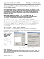
Once the text file is linked, the QuickControl Program
needs to access the register file properties so that it can
iterate through the entire array. Three Write Register
File (WRF) commands are needed to do this. The first
WRF command writes the non-volatile memory Start
Address, where the first row of data resides, to a user
register. The register file system assigns the start
address automatically upon linking to ensure that the
entire table will fit in non-volatile memory. The second
WRF command writes an Address Increment to another
register. The register file system assigns an address
increment based on the number of columns reported
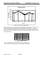
(col=4, see Figure 2) in the first line of the Register File
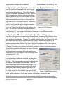
Figure 4: WRF Dialogue
Array. The third WRF command writes the Number of
Rows in the array to a third register. Specified in the first line of the Register File Array
(row=22, see fig. 2). See Register File System in SilverLode™ User Manual for details.
Configuring the IMS Command within the QuickControl Program
Once three user registers contain the Start Address, Address Increment, and Number of Rows
of the table, the IMS command has to start iterating through the data. The IMS command uses
seven registers in its operation. Register [17] contains a data indicator (see Checking for Stale
Data) in the upper word and the register reference number of the first user register that is
loaded with segment data in the lower word. Register [18] is used internally to hold the
segment time countdown. Register [19] holds a data loss deceleration value. This value will
only be used if there is an under-run of data to the IMS operation; the time value counted down
in Register [18] reaches zero before a new velocity segment is loaded into the user registers.
The four user registers are defined by the value in Register
[17]. The first holds the time data, the second position data,
the third acceleration data, and the fourth register holds
velocity data. In “Profile Playback – Ode to Joy.qcp” these
are Registers [30] – [34].
After the operational registers are loaded with data and the
four segment data registers are identified, they should be
loaded with the first row of segment data from the Register
File Array. This is accomplished via indirect addressing and
the Register Load Multiple (RLM) command. With the
“Indirect Addressing Mode” checkbox checked, the RLM
command uses the value in the Accumulator [10] as the
starting non-volatile memory address of the data to be
loaded into the segment data registers. Therefore, before
the RLM is issued, the Start Address from the first WRF
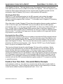
Figure 5: RLM Dialog window
must be copied into the Accumulator [10]. Then the RLM is
issued, loading registers 30-34 with time, position, acceleration, and velocity data.
After the first segment is queued into the data registers, the IMS command starts execution.
The IMS command requires two tasks running in a loop to ensure that it can iterate through the
QuickSilver Controls, Inc.
Page 6 of 11