1
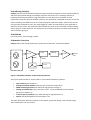
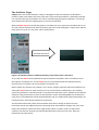
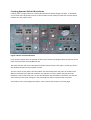
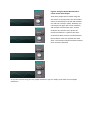
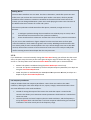
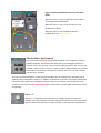
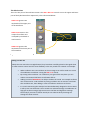
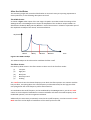
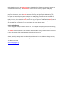
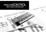
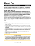
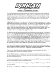
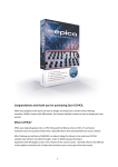
Catalyst VST by Broken Gadget
User Manual
Introducing Catalyst
Catalyst VST instrument blends and shapes oscillator waveforms together to form hybrid waveforms
which are then passed through an analogue style filter and chorus unit. The design focuses on
producing interesting waveforms using rectification in a way likely to be unfamiliar to most
synthesists outside the world of modular synthesis. The synthesiser is designed to be easy to use and
offers something a bit different from the usual subtractive synthesiser design. Some of the controls
may be a little unfamiliar to users, but a quick jiggle of a slider or knob will give you a good idea of
what the control can do. This manual has been written for those of you interested in understanding
what‘s going on ’under the hood’. The synthesiser is so intuitive you won’t need the manual open to
work out what’s going on.
Installation
Put Catalyst.dll in your VST plug in folder.
Schematic Overview
Catalyst follows the standard subtractive synthesiser architecture, as illustrated below:
V.C.F.
V.C.A.
OSC 1
gain
Chorus
Gain
Sound
out
cutoff
L.F.O.
OSC 2
ADSR
Figure 1: Simplified Schematic of the Catalyst Synthesiser
This layout will be familiar to anyone used to conventional subtractive synthesis:
•
•
•
•
•
•
Two oscillators are passed to a
Voltage controlled amplifier (VCA) the gain of which is shaped by an
ADSR envelope generator after which the signal passes through a
Voltage controlled filter (VCF), where the cutoff can be modulated by the envelope
generator in addition to
A low frequency oscillator (LFO). After filtering the signal passes to a
Chorus unit following which the overall gain is set.
The main refinement offered by Catalyst to this familiar synthesiser design is the oscillator stage.
This is explained in the next section.
The Oscillator Stage
Catalyst offers two audio oscillators. Catalyst is designed so that the oscillators are blended to
produce hybrid wave shapes where the upper part of the resultant waveform is formed by oscillator
one, and the lower part by oscillator two. This is achieved using half wave rectification. You may be
more familiar with the term clipping which is a form of rectification.
With the blend control in the half way position, oscillator one set to square and oscillator two set to
sine the resultant waveform will have the positive part of its cycle looking like a square wave and the
lower part of its cycle as a sine wave. This is shown below.
Resultant waveform
Figure 2: A hybrid waveform created by blending a square wave with a sine wave
As you shift the blend control upwards the hybrid waveform will feature more of oscillator one at
the expense of oscillator two. As the blend control is moved downwards the hybrid waveform
features more of oscillator two at the expense of oscillator one.
Both oscillator one and two can produce a sine, square, triangle, sawtooth and noise waveforms. By
setting the blend control at either extreme you can set up Catalyst as effectively a one oscillator
synth using waveforms commonly found on conventional subtractive synths. A blend of two identical
waveforms will yield results very close to dual oscillator synths. By blending different waveforms or
using some of the additional controls described below you can readily obtain hybrid waveshapes not
usually found on conventional subtractive synthesisers.
The illustration above will yield a static waveform which won’t change its shape over time.
Instrument sounds are subjectively more interesting when the waveform changes over time. Even
before the waveform reaches the filter stage Catalyst offers a number of ways to adjust how
oscillators one and two interact to produce hybrid waveforms that vary over time. These are
described in the next section.
Creating dynamic Hybrid Waveforms
Catalyst offers a range of ways to create hybrid waveforms which change over time. To introduce
you to some of the important controls in the oscillator section Catalyst comes with a simple patch,
number sixty four, Blank Frank.
Figure 3: Doesn’t Frank look blank?
If you haven’t already done so welcome Frank to your world by clicking the down arrow next to the
patch name and then selecting Blank Frank.
This patch has the chorus unit switched off and the low pass filter is fully open, so what you hear is
the unadorned output of the oscillator section.
The first control to play with is the Phase Mod. The Phase Mod shifts the phase of oscillator two.
When turned fully to the left both oscillator one and two are fully in phase meaning that their
waveforms start at the same time. As you shift the phase the waveforms of oscillator one and two
shift relative to each other along the x axis, meaning they fall out of phase with each other.
This leads to some interesting wave shapes, some of which are shown on the next page.
Figure 4: Using the Phase Mod Control to
create various wave shapes
These wave shapes were created using two
sine waves. In the top picture the Phase Mod
control is turned fully to the left and oscillator
one and two are fully in phase. Oscillator one
contributes the upper part of the waveform,
and oscillator two the lower part. As both
oscillators one and two are in phase the
resultant waveform is a perfect sine wave.
As the Phase Mod control is turned clockwise
the oscillators move out of phase with each
other. The resultant hybrid waveform becomes
more and more distorted.
As you can see even using two very simple waveforms you can readily create much more complex
waveforms.
Making Waves
The most basic waveform is a sine wave. This has no harmonics, sounds like a pure tone and
unlike noise you can hear that a sine wave has pitch. Unlike a sine wave, all other periodic
waveforms have harmonics. Harmonics contribute to the timbre of the sound. One of the
reasons you can distinguish between a piano and a violin playing the same note is because of
the different harmonic content of a violin and a piano.
The reason synthesisers include waveforms like square, sawtooth, triangle and so-on is
because:
(i)
(ii)
In analogue synthesiser design these waveforms are relatively easy to create, and so
have become the cornerstones of the synthesis vocabulary.
These waveforms have a harmonic content that is close to many acoustic instruments.
As you can see the waveforms in figure 4 depart from the initial sine wave to form quite
unusual waveforms, which makes for greater sonic novelty. Blending waveforms other than
sine waves yields yet more unusual hybrids. The way a sound changes over time is also adds
interest; the harmonic content of most instruments varies over time. Catalyst readily lends
itself to creating unusual wave shapes that also vary over time.
L.F.O.
If you hold down a note and manually change the Phase Mod setting you will hear that the sound
alters; the pitch stays the same yet the sound goes through a range of timbres like zingy, fat, thin
and so on. The drop down menu above the Phase Mod knob allows you to choose between:
•
•
•
Manual: The phase is modulated using the Phase Mod Depth control only.
Free LFO: The phase is modulated by the free LFO (Low Frequency Oscillator) at a depth set
using the Phase Mod Depth knob.
ADSR: The phase is modulated by the ADSR (Attack Decay Sustain Release) envelope at a
depth set by the Phase Mod Depth knob.
Low Frequency Oscillators
Catalyst includes three Low Frequency Oscillators –LFOs. These are similar to the audio
oscillators, offering the same wave shapes of sine, square, triangle, sawtooth and noise. There
are some differences to the audio oscillators:
•
•
Instead of routing the output of the LFOs to the audio the output is routed to the
controls. This allows you to automate various parameters which leads to a sound which
varies over time.
The LFOs operate at a lower frequency than the audio oscillators, and the frequency is
set by the Speed knob. This knob has a non linear response calibrated to give increased
resolution in the most critical part of the frequency range.
Figure 5: Routing modulation sources to the phase
offset
When the source is set to manual the phase offset is
set using the Phase Mod knob.
When the source is set to Free LFO the Free LFO
modulates the phase.
When the source is set to ADSR the phase is
modulated by the ADSR envelope.
The Oscillator Mod Control
As you have seen the blend control mixes oscillator 1 and 2 together to form a
hybrid waveshape. The blend control does this by controlling the amount of
oscillator one or two present in the resultant hybrid waveform. The mod controls
perform a similar function. There is a mod control for both oscillator one and two.
Each mod control features a LFO which modulates the point at which oscillator
one and two is rectified.
To recap, the hybrid waveform is formed from the upper part of oscillator one, and lower part of
oscillator two as illustrated in Figure 2. In addition to the blend control the mod controls determine
how much of the upper part of oscillator one and lower part of oscillator two contributes to the
resultant wave. In practice the mod controls yield sounds similar to pulse width modulation, chorus
and phasing.
Osc 1 > 2
The Osc 1 > 2 modulates the rectification of oscillator 2 with the output of
oscillator one. This produces more buzz and growl to the sound, and is particularly
apparent when oscillator one is tuned an octave or two lower than oscillator one.
The Mix Section
This is the last part of the oscillator section. The OSC 1 & 2 Post controls act on the upper and lower
part of the hybrid waveform respectively. This is illustrated below:
OSC1 Post governs the
amplitude of the upper part
of the waveform.
OSC1 Direct mixes in the
output of oscillator one
unshaped by the blend or
mod controls.
OSC2 Post governs the
amplitude of the lower part of
the waveform.
Figure 6: The mix section controls
Doing it in the mix
Whilst the mix controls are straightforward, they have been carefully placed in the signal chain
to offer intuitive control and also some flexibility in the way sounds are created. For example:
•
•
•
•
When oscillator one is turned down in the mix stage it can still be used as a source
of modulation to oscillator 2 using the OSC 1 > 2 control.
By turning either oscillator 1 or oscillator 2 post gain all the way down you can
achieve conventional half wave rectification effects.
Adding in some of OSC1Direct can help to thicken the sound. For example oscillator
one can be used as a sub oscillator by tuning oscillator one an octave or two lower
than oscillator two, then adding in some of oscillator one direct to the mix.
It is worth mentioning that Catalyst has been deliberately designed so that at times
it will tip over into distortion. These sounds are achieved through a combination of
high gain at the mix stage, high resonance in the filter and high drive settings.
Conversely if you want a cleaner sound you can achieve this by lowering the
settings for these controls.
After the Oscillator
The remaining stages and controls will be familiar to most with even just a passing acquaintance
with synthesisers, so the following descriptions are brief.
The ADSR Section
As shown in figure 1 the output of the mix stage is shaped in accordance with the settings of the
ADSR generator. The ADSR generator shapes the amplitude of the oscillators output. ADSR is an
abbreviation of Attack, Decay, Sustain, Release. Each of these terms is related to a particular part of
the amplitude envelope of the sound, as illustrated below.
Amplitude
Attack
Decay
Sustain
Release
Time
Figure 6: An ADSR envelope
The ADSR envelope can also be used to modulate the filter cutoff.
The Filter Section
Use the drop down menu in the filter section to select one of the five filter modes:
(i)
(ii)
(iii)
(iv)
(v)
Low pass
High pass
Band pass
Band reject and
Peaking
The cutoff control sets the relevant frequency over which the filter operates. For instance with the
low pass filter, everything above the cutoff frequency will be attenuated; for the high pass filter
everything below the cutoff frequency will be attenuated etc.
As noted above the cutoff frequency can be modulated by the ADSR generator, use the env mod
control to set the depth of modulation. Positive modulation will cause the cutoff frequency to be
modulated upwards, vice versa negative modulation.
Additionally the Free LFO is permanently routed to the cutoff frequency; use the Free LFO’s Cutoff
Mod control to set the depth of modulation of the cutoff by the Free LFO.
Back in the filter section, the Resonance control shapes the filter’s frequency responses, boosting it
around the cutoff frequency. The Resonance control is the key to overtly squelchy and synthy
sounds.
Lastly the Track control modulates the filter cutoff in proportion to the pitch of the note being
played. In other words, when the Track control is turned up, the higher up the keyboard you play,
the higher the cutoff frequency. This is a helpful way of adjusting your sound so that it sounds like
you want in both the lower and the higher registers. When you have adjusted your sound as you like
it play a low note, then tweak the Track control, then play a higher note and tweak the Track control
again. You will probably find that you will need to tweak the cutoff too, eventually you should be
able to tweak your sound so that it is to your liking in the most relevant range.
Driving to the Chorus
To finish things off Catalyst includes a chorus unit. This is helpful in thickening the sound and adding
some swirl and movement. To save processor load switch this section off if you aren’t using it.
The VelSens control is used to set the sensitivity of the sound to velocity; this determines the extent
to which the volume of the sound increases the harder the keys are hit.
To finish the Drive control sets the overall volume of the sound. It has been called Drive rather than
Volume, as at high settings some sounds can become distorted. This is a deliberate design decision;
if you don’t want distortion reduce the setting of drive, resonance and the mix controls.
Tim Wilson, June 2012
www.brokengadget.org