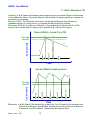
1
AEGIS
Water Treatment Controller
Installation & Operating
Manual
AEGIS User Manual
CONTENTS
Safety
Navigation
A. HELP
Yourcont
r
ol
l
ersensorset
,i
t
’
swi
r
i
ngandconf
i
gur
at
i
on.
Typical installation for your controller type.
B. START-UP
Modifying your controller for this site.
1. Day-to-Day Operation
1.1
1.2
1.3
1.4
Main Menu: Sensors, Pumps, Solenoids & Valves
Checking & Clearing Alarms
View & Adjust Setpoints
Priming-Testing Pumps & Solenoids
2. Chemi
calFeedCont
r
ol
s:I
nhi
bi
t
or
,Aci
d,Bl
each,Ami
ne…
2.1
2.2
2.3
2.4
2.5
2.6
2.7
2.8
2.9
2.10
Chemical Feed 101
Water Meter Feed
Bleed Based Feed
Sensor Controlled ON/OFF Feed
Proportional Feed
Base Feed
Limiting Feed & Alarms
No Feed on No Flow
Blocking a Feed
Feed Diagnostics
3. Biocides : Feeding by Time & Date
3.1
3.2
3.3
3.4
Setting & Viewing Events
Prebleed - Lockout
Event Cycle
Event Diagnostics
4. Sensors: Conductivity, pH, ORP, Corrosion, 4-20mA…
4.1
4.2
4.3
4.4
4.5
4.6
Sensors 101
Sensor Calibration
Sensor Alarms
Sensor Configure
Sensor Compensation
Sensor Diagnostics
5. Measuring Volume: WaterMeters, Inventory, Verify Feed
5.1
5.2
5.3
5.4
5.5
5.6
Aegis _User 7/08
Meters 101
Configuring a New Meter
Feed Verification & Inventory
Cycle Controls
Copying Meters
Meter Diagnostics
2
AEGIS User Manual
6. Cooling Tower Bleed
6.1
6.2
6.3
6.4
Make it Bleed 101
Bleed Alarms
Variable Cycles
Diagnostics
7. Boiler Blowdown
7.1
7.2
7.3
7.4
Boiler Blowdown 101
Adjusting Boiler Blowdown Timing
Fail-to-Sample
Sensor Watch & Blowdown Diagnostics
8. Flowswitches & Contact Sets
8.1
8.2
8.3
8.4
8.5
8.6
Contact Sets 101
Switching Meters & Contact Sets
Contact Set Alarms
Mirroring Outputs
Inverting Contact Sets
Contact Set Controls
9. Frequency Controlled Pumps
9.1
9.2
9.3
9.4
Selecting a Pump
Copying a Pump Volume
Adjusting ml/stroke
Setting SPM Rating
10. 4-20mA Outputs
10.1 4-20mA Output Setpoints
10.2 4-20mA Output Configuration
11. System Settings
11.1
11.2
11.3
11.4
11.5
11.6
11.7
11.8
Passwords
Time & Date
Keypress-Alarm Log
Enabling Inputs & Outputs
Metric & U.S. Units
Configurations
Communications
System Diagnostic
12. Product Support
12.1 Application and Technical Support
12.2 Specifications
C.‘
LB’LANBr
owserOpt
i
on
R.‘
RM’Remot
eModem Opt
i
on
Aegis _User 7/08
3
AEGIS User Manual
Safety
Electrical Shock Hazard
Opening the controller enclosure with the controller plugged in, exposes the user
to AC line voltages on the lower of the two controller circuit boards.
Ground the controller AC power to the ground screw labeled
of the aluminum backplate.
and located on the bottom, right
External, 120VAC socket or optional plug boxes are provided with controllers installed in North
America. Both are grounded to the ground screw labeled
aluminum backplate.
located on the bottom, center of the
USER WARNING : CAUTION
Water Treatment Controllers operate steam and water valves and may pump
hazardous, corrosive and toxic chemicals. Opening the controller enclosure
exposes user to the risk of electrical shock at power line voltages.
Understand fully the implications of the control setpoints, interlocks and alarms
that you select. Harm to personnel and damage to equipment may result from
mis-application.
Unplug or turn OFF the AC power to the controller if you have any concerns
regarding safety or incorrect controller operation and notify supervisory staff.
YOUR CONTROLLER
AEGIS Controllers are supplied in many different configurations, part numbers
and sensor sets. Applications extend beyond water treatment.
The HELP section depicts the installation plumbing header showing the sensor
set supplied with your controller. It also includes the information for terminating
the sensors supplied with your specific controller part number.
The START-UP section is specific to your application and details modifying
the default controller settings for your site.
Aegis _User 7/08
4
AEGIS User Manual
Navigation
1of3
UP & DOWN to view options
or to EDIT numbers
KEYPAD
If you get lost in a sub-menu, press EXIT &y
ou’
l
l
st
opwhaty
ou’
r
edoi
ng&mov
ebackt
ot
hemai
n Move RIGHT to select next
field when EDITing
menu
An ENTER symbol on the display signals that
there are sub-menus available,
ENTER to select an option
& to execute EDITing
EXIT to escape option,
info display or EDITing
MAIN MENU
The sensors and controls in the main menu vary with your controller part number and
sensors and pumps that you enable or disable.
The main menu groups sensors with the pumps or solenoids that they control so you may
find the menu order changing when you change an inhibitor pump for Bleed then Feed
control to Water Meter ppm control.
Where are Sensors, Solenoids, Valves & Pumps Connected
You may modify the names of sensors, pumps and solenoids but the controller tags each
input with a letter A to Z and each output with a number 1 to 9 representing where each is
wired.
Inputs A, B and G and O to V have fixed wiring terminals on the upper controller board.
A is always a conductivity sensor, B a temperature sensor and G a 4-20mA input
Inputs O to V may be individually selected to be either a water meter, volume input or a
contact set, flowswitch input.
Terminals for outputs 1 to 5 are located on the lower board.
They are ON/OFF power relays that switch 120 or 230VAC to pumps, valves and solenoids.
Terminals for outputs 6 to 9 are also located on the lower circuit board.
They are electronic switches used to frequency control pumps.
Inputs C-D and E-F are used for plug-in sensor cards which add optional conductivity, pH,
ORP, corrosion rate, 4-20mA inputs & outputs to the controller.
Sensor inputs H to N and meter/contact set inputs W to Z don’
tphy
sically exist in the
controller and are used to calculate ppm & inventory, log manual entries, sum water meters
& many other advanced controller functions.
Aegis _User 7/08
5
AEGIS User Manual
Navigation
2of3
BROWSER
Cont
r
ol
l
er
swi
t
ht
he‘
LB’LAN-Browser option include a built-in command & control web server with
real time views of your controller operation.
Youcanbr
owsewi
t
hMoz
i
l
l
a’
sFi
r
ef
oxorI
nt
er
netEx
pl
or
er7ov
era10BaseTEt
her
netc
onnect
i
on
or the internal modem, if installed.
I
ft
he‘
LB’opt
i
oni
si
ncl
udedi
ny
ourcont
r
ol
l
er
,t
heBr
owserappendi
x‘
C’hasbeenaddedt
ot
hi
s
manual
Sidebars: Are used to explain typical uses for feed and control functions.
Sidebars are at the bottom of the page detailing the function.
New users & users new to water treatment will find these explanations helpful.
Aegis _User 7/08
6
AEGIS User Manual
Navigation
3of3
FREQUENCY CONTROLLED PUMPS
Aegis controllers combine the 5 ON/OFF controls with 4 frequency controls.
Depending on your feed application, frequency controlled pumps may deliver more accurate feed,
easier to understand setpoints and fed volume tracking, without increasing pump cost.
Frequency controlled pumps & the innovative way the Aegis uses them may new to you.
The Aegis lets you mix & match ON/OFF & frequency controls to fit your site:
Typical
Applications
Typical Inhibitor Feed
Blowdown or Bleed
Typical Biocide Feed
Acid Feed
Proportional Feed
ON/OFF
Controller switches AC power
ON/OFF to pump or solenoid.
Water meter control
turns ON the pump for 10
seconds every 100 gallons of
make-up
Controller turns ON/OFF
solenoid or motorized valve.
Turn-on pump for 45 minutes
@ 7:00 every Tuesday
Turn ON pump when pH greater
than 7.65 & OFF when pH less
than 7.55
Requires a 4-20mA controlled
pump
Tank Level Alarms
Ppm Calculations
Requires feed meter on pump
outlet or inlet.
Typical Base Feed
Turn pump ON for 45 seconds
every 5 minutes
Relies on user to correctly set
pump stroke & frequency
User Support
Frequency
Controller-to-pump cable varies
stroke rate.
User sets target inhibitor ppm &
control meters inhibitor based on
make-up volume.
Not used
Turn-on pump for 0.535 Gallons
@ 7:00 every Tuesday
Increase the acid feed rate as the
pH increases.
Any sensor can control the feed
rate from a 1000:1 turn down to
maximum feed rate.
Calculate tank level from fed
volume. More than one pump may
share a tank.
Feed @ 4.5mL/minute
Won’
tl
ety
ous
etf
eedr
at
egr
eat
er
than the pump can deliver.
Auto-switches from proportional to
MAX rate depending on feed mode.
You can select one of 6 of the most popular ProMinent pumps for each frequency control which
automatically sets the maximum stroke rate and volume per stroke OR you can define a mL/stroke
andmax
i
mum f
r
equencyf
oranymanuf
act
ur
er
’
sf
r
equencycont
r
ol
l
edpump.
Aegis _User 7/08
7
AEGIS User Manual
1.0 Day-to-Day Operation
1.1 Main Menu
This is the power-on day of week & time display.
The Serial Number tracks special features &
the sensor set installed in your controller.
Press ENTER to view-set system settings
Active alarms are displayed by the letter, A..Z, of the input
or the number 1..9, of the output
Press ENTER to reset alarms, to view alarm detail,
or to scroll the key-press log,
Present value of the conductivity connected to
sensori
nput‘
A’
.Updat
esev
er
ysecond.
Press ENTER to Calibrate, view-set Alarms, Compensation
Conduc
t
i
v
i
t
y‘
A’cont
r
ol
st
heBl
eedSol
enoi
dc
onnect
edt
o
out
put‘
2’
s
ot
heydi
spl
ayt
oget
her
.
The Bleed has been ON for 25.6 minutes this cycle.
Press ENTER to view-setSet
poi
nt
s,Conf
i
gur
at
i
on…
Thu 16:54:10
S/N: A076X0486
Alarms
none
Conductivity
1134 uS
A
Bleed Solenoid 2
ON
25.6 min
Tower Make-up
26500 gal
O
Wat
ermet
er‘
O’cont
r
ol
st
hepumpc
onnect
edt
oout
put‘
1’
which is OFF, waiting for the meter to measure make-up.
Press ENTER to view-set Feed Rate, Feed Li
mi
t
s…
Inhibitor
OFF:Setpoints
1
AnORPs
ens
ori
sconnect
edt
ocont
r
ol
l
eri
nput‘
C’
.
Aegis controllers may include 1..4 ORP or pH sensors.
Press ENTER t
oCal
i
br
at
e,v
i
ewDi
agnost
i
cs,Conf
i
gur
e…
ORP Sensor
286.4 mV
C
Volume from midnight on the water meter
connect
edt
oi
nput‘
O’
Press ENTER to view-setTy
pe,AnnualVol
ume…
The ORP sensor frequency controls a pump connected to
out
put‘
6’whi
chhaspumped 1.317 Gallons this feed cycle
.Press ENTER t
oAdj
ustSet
poi
nt
s
,changePumpTy
pe…
At
emper
at
ur
esens
ori
sconnec
t
edt
ocont
r
ol
l
eri
nput‘
B’
I
t
’
snotusedf
orcont
r
olsoi
tdi
s
pl
ay
saf
t
ert
hecont
r
ol
s
Press ENTER to Calibrate, view Diagnostics, Configure…
6
Oxidant Pump
ON
1.317 Gal
Temperature
86.24 F
continued
Aegis _User 7/08
8
B
AEGIS User Manual
1.1 Main Menu cont.
Some controllers may include corrosion rate monitoring.
Acoppercor
r
osi
onsensori
sconnect
edt
oc
ont
r
ol
l
eri
nput‘
E’
& measuring a rate of 0.26 mils per year.
Press ENTER to change metals, view di
agnost
i
cs…
Users may use the controller to key in results of chemical
tests. These results may be used to alarm, adjust feed
r
at
es… Ther
esul
tofadr
opt
esti
sent
er
ed,l
oggedand
di
spl
ay
edoncont
r
oli
nput‘
J’
This controller measures the Tower Bleed volume on meter
i
nput‘
P’
.Thev
ol
umef
r
om mi
dni
ghtmaybebei
ngusedf
or
cycle control and/or evaporation credits
A second make-up source may be measured by turning on
anunusedi
nput
;‘
Q’i
nt
hi
sex
ampl
e.I
tmayt
henbesummed
with the potable make-up to feed inhibitor
I
nput‘
S’i
st
hedef
aul
tf
l
owswi
t
chi
nput
.I
t
’
sbeenONt
oday
f
or10.
89hour
s&si
nc
ei
tnow16:
54,t
hi
st
ower
’
s
re-circulation pumps turned ON @ 6:00AM
You can edit the name of any input or output.
This biocide can be fed on a 1,7 or 28 days cycle.
You can set chemicals to feed before or after other
chemicals to prevent feed line reactions
or to sequence product delivery
You can disable unused sensors, pumps or relays
to un-clutter the display and turn them
back ON as site needs change.
Plug-in a new sensor card and the
controller auto reconfigures
Key EXIT anytime on the Main Menu &y
ou’
l
lget
back to this power ON display
Aegis _User 7/08
9
Copper Corr.
0.26 mpy
E
Drop Test
12 drp
J
Bleed Meter
8210 gal
P
Grey Water
3825 gal
Q
Flowswitch
ON
10.89 Hr
S
3
456 Biocide
ON
10.2 min
Dispersant
OFF:No Event
7
PowerRelay_4
OFF:No control
4
Thu 16:54:10
S/N: A076X0486
AEGIS User Manual
1.2 Checking & Clearing Alarms
Key DOWN from the power ON display to view alarms.
I
nt
hi
sex
ampl
e,t
hesensorconnect
edt
oi
nput‘
B’andt
he
pumpors
ol
enoi
dt
ocont
r
ol
l
edbyRel
ay‘
2’hav
eal
ar
med
Press ENTER to view or clear Alarms
Press ENTER to clear Alarms, resets all alarmed feeds and
controls, zeroing owed time & volume.,
and resets the delay on alarm for all sensors
Thu 16:54:10
S/N: A076X0486
Alarms
B 2
Clear Alarms
Alarms
Exit the acknowledge display by pressing ENTER or any key
Cleared Alarms
Reset All
Returns to the main menu Alarms display.
See Sidebar @ bottom of page.
________________________________________________
Alarms
none
View Alarms
Press ENTER then DOWN to view active alarms.
Al
ar
msdi
s
pl
ayunt
i
lcl
ear
edsoy
ou’
l
lknowt
her
ewasa
problem although it may have occurred
when you were not @ the controller.
Press ENTER at Alarms
and UP or DOWN to view active alarms.
‘
B’i
saTemper
ature sensor which has exceeded or is
ex
ceedi
ngi
t
’
shi
ghal
ar
m.
‘
2’i
sabl
eedwhi
chhasex
ceedi
t
’
smi
nut
esONt
odayal
ar
m.
Bleed solenoids are usually set to stay ON after alarming.
Pumps are usually set to turn OFF on alarm
Alarms
B 2
and
Alarms
Activity Log
Temperature B
Alarmed High
Bleed Valve 2
Limit,Time/Day
Sidebar: Feed limit and water meter alarms will immediately re-trip unless you adjust the alarm
limits. Sensor alarms will re-t
r
i
paf
t
ert
heuserset‘
Del
ay
’unl
esst
hef
aul
ti
sc
or
r
ect
ed.
Aegis _User 7/08
10
AEGIS User Manual
1.3 View & Adjust Setpoints
Key UP or DOWN to the target Pump, Valve or Solenoid
then press ENTER.
Press ENTER @ Setpoints.
Setpoint types differ with control type
and ON/OFF or frequency.
Refer to the following page for typical
chemical feed setpoints.
When the controlling conductivity exceeds
1200 uS the Tower Bleed will TurnON.
Key ENTER to adjust.
When the controlling conductivity falls below
1180 uS the Tower Bleed will TurnOFF.
Key ENTER to adjust.
Key RIGHT to move the underline and then
UP or DOWN to change the number.
Press ENTER to change the setpoint
or EXIT to leave unchanged
Adjust Setpoints
Tower Bleed
2
ON
16.2min
Setpoints
Test-Prime
TurnON setpoint
1200 uS
OFF Setpoint
1180 uS
Editing, or Exit
1190 uS
then
OFF Setpoint
1190 uS
Sidebar:
Relays controlled by sensors power Pumps and Solenoids ON and OFF.
(Relays are outputs 1 to 5 )
Frequency controlled Pumps feed chemicals at varying rates.
(Frequency controlled pumps are outputs 6 to 9)
Tower Bleed solenoids use Setpoints 5uS to 20uS apart so that short bleeds are followed by short
feeds. The resulting control has minimum variation in Inhibitor ppm and operates as close as
possible to the target cycles of concentration.
ON-OFF Acid pumps use setpoints 0.05 pH apart so that the delay between feeding acid and
meas
ur
i
ngi
t
’
spHdoesnotc
aus
ewi
depHswi
ngs.
Aegis _User 7/08
11
AEGIS User Manual
1.3 View & Adjust Setpoints
Meter Feed
The Inhibitor pump powered ON/OFF by relay 1 is ON
and Owes 2.6 minutes of feed time..
This inhibitor is fed based on the volume
measured by the tower make-up meter
Key ENTER once to Setpoints and again to view the
volume setpoint. Press ENTER to adjust.
Press DOWN to view the ON time setpoint.
Every 100 Gallons of make-up the pump
runs for 12 seconds.
Press ENTER to adjust.
Key RIGHT to move the underline and then
UP or DOWN to change the number.
Press ENTER to change the setpoint
or EXIT to leave unchanged
I
nt
hi
sex
ampl
e,we’
v
ei
ncr
easedt
hefeed rate by 25% by
extending the ON time from 12 to 15 seconds.
______________________________________________
Cooling towers without make-up meters, use
Bleed then Feed control for Inhibitor feed.
Example: After the tower has bled for 8.4 minutes,
the Inhibitor pump turns ON for 8.4 minutes.
Key ENTER twice to view the present Bleed then Feed
set
poi
nt
.I
nt
hi
sex
ampl
ei
t
’
s50%. If the bleed in ON for 8.4
minutes, inhibitor feeds for 4.2 minutes.
Press ENTER to adjust.
Key RIGHT to move the underline and then
UP or DOWN to change the number.
Press ENTER to change the setpoint
or EXIT to leave unchanged.
I
nt
hi
sex
ampl
e,we’
v
ei
ncr
easedt
hef
eedr
at
eby24% by
extending the ON time from 50% to 62% seconds.
Aegis _User 7/08
12
Inhibitor
1
ON:Owes
2.6min
and
Measure Volume
100 G
And Turn ON for
12 sec
Editing, or Exit
15 sec
then
And Turn ON for
15 sec
Bleed then Feed:
Inhibitor
OFF:Setpoints
1
Setpoints
Test-Prime
Bleed then Feed
50%
Editing, or Exit
62%
then
Bleed then Feed
62%
AEGIS User Manual
1.3 View & Adjust Setpoints
Key UP or DOWN to the target Pump, Valve or Solenoid
then press ENTER.
The Product Pump frequency controlled by output 7 is ON
and Owes 0.051 Gallons of feed.
This chemical is fed based on the volume
measured by the tower make-up meter
Key ENTER once to Setpoints and again to view the
volume setpoint. Press ENTER to adjust.
Press DOWN to view the ppm setpoint.
Every 75 Gallons of make-up
25 ppm of product is fed.
Press ENTER to adjust.
Key RIGHT to move the underline and then
UP or DOWN to change the number.
Adjust Setpoints
ppm Feed
Product Pump
7
ON:Owes
0.051G
Setpoints
Test-Prime
Measure Volume
75 G
Then Feed
25 ppm
Press ENTER to change the setpoint
or EXIT to leave unchanged
I
nt
hi
sex
ampl
e,we’
v
ei
ncr
easedt
hef
eedr
at
eby40% by
extending the feed rate from 25 to 35 ppm
Editing, or Exit
35 ppm
then
Then Feed
35 ppm
Sidebar:
Control
l
er
swi
t
ht
he‘
metric’sy
st
em opt
i
onset
,di
spl
ayv
ol
umesi
nLiters, not Gallons
Inhibitors typically have a recommended ppm concentration for a target hardness or corrosion
r
at
e.I
nt
hi
spage’
sex
ampl
e,we’
r
ef
eedi
ngat25ppm whi
chi
s0.
0019Gal
l
onsor7mL for every 75
Gallons of make-up.
The Measure Volume does not have to be the Gallons/Contact of the make-up meter.
The controller does the math.
The controller knows the mL/stroke rating for the No.7 pump & it knows how many times the pump
has stroked, so the controller knows the volume fed.
Aegis _User 7/08
13
AEGIS User Manual
1.3 View & Adjust Setpoints
Key UP or DOWN to the target Pump, Valve or Solenoid
then press ENTER.
The Acid Pump, frequency controlled by output 6 is ON
and feeding at 65.84% of maximum SPM (strokes/minute).
This chemical is fed based on the value of a pH sensor.
Key ENTER once to Setpoints and again to view the
100%ON Setpoint.AtpH’
sgr
eat
ert
han7.
50t
he
‘
6’Acid Pump is @ maximum, rated SPM.
Press ENTER to adjust.
Adjust Setpoints
Sensor Feed
Acid Pump
6
Feed@ 65.84%
Setpoints
Test-Prime
100%ON Setpoint
7.50 pH
Press DOWN to view the OFF Setpoint setpoint.
AtpH’
sl
esst
han7.
25t
he‘
6’Acid Pump is OFF.
Press ENTER to adjust.
Key RIGHT to move the underline and then
UP or DOWN to change the number.
Press ENTER to change the setpoint
or EXIT to leave unchanged
OFF Setpoint
7.25 pH
Editing, or Exit
7.37 pH
then
I
nt
hi
sex
ampl
e,we’
ve narrowed the control range from
0.25pH (7.5-7.25) to 0.13pH (7.5-7.37).
OFF Setpoint
7.37 pH
Sidebar:
Thecont
r
ol
l
erknowst
hepumpt
y
pec
onnect
edt
oout
put‘
6’andi
t
sr
at
edmax
i
mum SPM.
Pumps of varying SPM and ml/stroke rating may be controlled at the same time.
The Measure Volume does not have to be the Gallons/Contact of the make-up meter.
The controller does the math so use setpoints that make sense to you.
I
nt
hi
sex
ampl
e,t
hegr
een‘
P6’i
ndi
c
at
i
ngLEDont
hel
owercont
r
ol
l
er board flashes at the pump
stroke rate. As the feed rate approaches zero, the time between flashes increases.
Anysensor
:t
emper
at
ur
e,st
r
eam demand,cor
r
osi
onr
at
e,ORP… maybeusedt
of
r
equenc
y
cont
r
olanypumpconnect
edt
oout
put
s‘
6’t
o‘
9’del
i
v
er
i
ng proportional control without using
4-20mA controlled pumps.
Aegis _User 7/08
14
AEGIS User Manual
1.4 Priming-Testing Pumps & Solenoids
Key UP or DOWN to the target Pump, Valve or Solenoid
then press ENTER.
The Oxidant pump controlled by relay 5 is OFF.
Test-Prime
Oxidant
OFF: No Event
5
and
Key ENTER and DOWN to Test-Prime.
.
Key ENTER again to view or adjust the Prime ON time
Relays 1 to 5 default to 5 minutes.
Frequency controlled pumps 6 to 9 default to 100mL.
Press ENTER to adjust ON time or feed volume.
If you key ENTER t
wi
cey
ou’
l
lt
ur
nONf
or
the default time or volume
Press ENTER to adjust.
Key RIGHT to move the underline and then
UP or DOWN to change the number.
Press ENTER to change the prime time
or EXIT to leave unchanged.
Test-Prime
BioFeed Event
Prime Output
5.0 min
Editing, or Exit
15. min
then
5
Oxidant
ON:Owes 14.9 min
I
nt
hi
sex
ampl
e,we’
r
epr
i
mi
ngt
heOxidant pump for 15
minutes. Oxidant now displays ON and
counts down the owed time or volume.
Sidebar:
Priming may also be used to slug feed on system start-up in addition to testing pumps,
valves or solenoids.
Ending Prime-Test:
Clear Alarms, Section 1.2 ends all owed time & volume for all pumps and solenoids.
Individual pumps may be reset by clearing the alarm. Refer to 2.7 Limiting Feed & Alarms
Fail to Prime:
A pump or solenoid that is Interlocked, Blocked or OFF on alarm will not Prime.
The time or volume owed will be fed when the reason for no feed is removed.
The main menu display for the target pump or solenoid will display the reason for fail to prime
And the Diagnostic sub-menu will provide detail.
If the green LED on the lower controller circuit board is ON, the pump or valve connected to that
output 1 to 9 should also be ON
Aegis _User 7/08
15
AEGIS User Manual
2. Chemical Feed Controls: Inhibitor,
Aci
d,Bl
each,Ami
ne…
2.1
Chemical Feed 101
Feed Methods: Water treatment uses 5 methods to feed chemicals. Make-up, Bleed and Sensor
methods responds to increasing load by increasing the volume fed to maintain a target ppm.
Each method has its fit for cost, reliability, feed accuracy and water treatment system size & type.
Feed
Method
Make-up
Bleed
Sensor
How does it work
Cooling Towers:
Feed when the cooling tower
make-up water meter
measures volume.
Boilers:
Feed when the boiler feed
water meter measures
volume.
Bleed & Feed
Feed when the bleed
solenoid is ON
Bleed then Feed
Feed after the bleed turns
OFF proportional to the time
the bleed was ON.
ON/OFF
Above the ON setpoint the
pump turns ON and below
the OFF setpoint the pump is
OFF
Proportional
Feed rate varies linearly from
OFF at the Turn OFF
setpoint to maximum feed
rate at the 100% ON setpoint
Chemical
Fed
Inhibitor
Typical
Applications
Towers may use more than one
make-up source or may control
based on bleed volume.
Boiler Treatment
Boilers may use a feedwater or
softened make-up water meter.
A contact set, ON when the
feedwater pump is ON is often
used as a make-up meter.
Cooling towers where the bleed
solenoid is ON more than 50% of
the time.
Inhibitor
Inhibitor
Acid, Oxidant,
Amine, Sulfite,
Disper
sant
….
Proportional feeds use variable
frequency, time modulation and
4-20mA to control feed.
Base
While the tower’
sr
unni
ngor Sulfite,
the boiler is on-line; feed
Amine,
chemical
Boiler Treatment
Timed
Feed occurs at a user set
time & day.
Aegis _User 7/08
Biocides
Oxidants
Dispersants
16
Towers with correctly sized bleeds,
ON less than 50% at maximum
load.
pH, ORP, conductivity,
temperature, steaming rate,
corrosion rate, drop count, GPM
make-up & many other sensors
control these pumps.
Small boilers provide a contact set,
closed when the boiler is on-line.
Works best when the boiler load is
constant.
Refer to Section 3. of this manual
AEGIS User Manual
2.1
Chemical Feed 101
If the concentration of chemical in your heating or cooling system is at the target ppm then all you
have to do is add chemical to treat the make-up.Ty
pi
cal
l
yy
ou’
l
lestimate a feed rate, adjusting in
subsequent weeks as indicated by ppm level testing.
Check Pump Rating
Pumps are rated for Gallons/hour, Liters/hour pumping into a nominal feed line head or back
pressure. The lower the back pressure, the higher the pumping rate. The following table is for
ProMinent pumps feeding into a 40 PSI feed line, typical for cooling towers.
Pump Type
ml/stroke
Liters/hr
Gallons/hr
1601
0.13
1.404
0.371
1602
0.24
2.592
0.685
1001
0.10
1.080
0.285
1002
0.24
2.592
0.685
0704
0.42
4.536
1.198
0705
0.50
5.400
1.427
Your pump type may differ. These pumps are typical for small to medium cooling towers or boilers
Example: If you expected a cooling tower to make-up 50,000 Gallons over 12 hours & you
needed to feed a 50 ppm product,y
ou’
df
eed2.
5Gal
l
onsor9.
46L.Si
nceact
ualwat
erus
ei
snot
linear over 12 hours & peaks around 2-3PM,y
ou’
dpr
obabl
ysel
ectan0704pumpov
era1601.
Feed Setpoints: Frequency Controlled Pumps
Water Meter Feed:
Adjust the Measure Volume setpoint to 100G or L and the then Feed setpoint to 50ppm
Bleed then Feed:
If you expected the bleed to be ON 25% of the time, it would be on for 3 hours in our 12 hour
example. In those 3 hours we need to feed 9.46L or 52.5mL/min
(9460mL/180 minutes). Adjust the mL/min setpoint to 53. At 180SPM type 0704 pump can feed
@ a max. of 75.6 mL/min so the controller will allow the setpoint.
Feed Setpoints: ON/OFF Pumps
Water Meter Feed:
At50ppm we’
l
lneedt
of
eed19mLf
orev
er
y100Gal
l
onsofmake-up.
If the 0704 pump is set to 100% stroke & frequency, it will need to be ON for 15 seconds.
( A 0704 pump feeds @ 75.6mL/min. 19mL/75.6mL x 60 secs = 15 sec.)
Adjust the Measure Volume setpoint to 100 and the Turn ON for setpoint to 15 sec.
Bleed then Feed:
If you expected the bleed to be ON 25% of the time, it would be on for 3 hours in our 12 hour
example. In those 3 hours we need to feed 9.46L or 52.5mL/min
(9460mL/180 minutes). Adjust the mL/min setpoint to 53. At 180SPM type 0704 pump can feed
@ a max. of 75.6 mL/min so 52.5mL/min = 69%.. Adjust the % setpoint to 69.
Aegis _User 7/08
17
AEGIS User Manual
2.2 Water Meter Feed
To view or modify the meter controlling the feed,
key UP or DOWN to the target Pump, & press ENTER.
In this example, the Inhibitor pump is powered by
relay 1 and has no controlling sensor or water meter.
Key ENTER & DOWN to Configure.
Controlling Meter
Inhibitor
1
OFF:No control
and
Configure
Alarms-Limits
Key ENTER, ENTER to modify the controlling sensor-meter.
Key UP or DOWN to change the sensor-meter.
Only enabled meters, contact sets and
sensors will display as you scroll.
Water &Met
er
sar
et
y
pi
cal
l
yi
nput
s‘
O’t
hr
ough‘
R’
Press ENTER to change the control
or EXIT to leave unchanged
Control by:
No Control
Editing, or Exit
O
then
Key RIGHT to add (+), subtract (-) or
sequence (:) other water meters.
Control by:
O
In this example we have set the Inhibitor pump control to
the water connec
t
edt
ocont
r
ol
l
eri
nput‘
O’
Sidebar:
Water meter and Feedwater Meter based controls feed proportional to load to maintain a target
ppm of the fed chemical. Inhibitors, Boiler Treatment and Amines are usually fed to achieve a
target ppm and therefore frequently meter controlled.
Meter based feeds are among the most reliable, accurate and simplest ways to feed.
The cost of installing a water meter is offset by the resulting feed reliability.
Summing Meters:
Up to 4 meters may be summed to control a pump. Use when towers have more than 1 make-up.
Sequencing Meters:
Refer to 5.3 Feed Verification & 5.4 Cycle Controls.
Oxidizing chemicals like bleach are almost never feed using a water meter since the demand is
not proportional to the make-up volume.
pH correction, feeding acid based on make-up volume, only works if make-up water chemistry is
constant. Even then a monitoring pH sensor is required.
Aegis _User 7/08
18
AEGIS User Manual
2.3 Bleed Based Feed
To view or modify the pump feed method, key
UP or DOWN to the target Pump, & press ENTER.
Bleed then Feed
Inhibitor
1
OFF:No Control
In this example, the Inhibitor pump is powered by
relay 1 and has no feed method set.
and
Key ENTER & DOWN to Configure.
Configure
Alarms-Limits
and
Key ENTER, UP to Special Control & then key ENTER.
Key UP or DOWN to view Special Controls that can be
used without a controller sensor or water meter.
Press ENTER to select Bleed thenFeed
or EXIT to leave @ None
Special Controls that now display Bleed thenFeed.
I
t
’
ssetat50%.Ref
ert
o1.3 View & Adjust Setpoints
Now when we view the Inhibitor pump, it displays
OFF:Setpoints, indicating that a control is active.
Special Control
None
and
Special Control
Bleed thenFeed
Special Control
Bleed thenFeed
Inhibitor
OFF:Setpoints
1
Sidebar:
Bleed then Feed is used to feed cooling tower inhibitor when a make-up meter is not available and
the bleed is ON for less than 50% of the time that the tower is on-line.
If the tower Bleeds for X Minutes, the Inhibitor is fed for a user set % of X minutes AFTER the
bl
eedends.I
t
’
sabet
t
erwayt
of
eedi
nhi
bi
t
orf
orsmal
lcool
i
ngt
ower
st
hanBl
eed&Feedsi
nce
less inhibitor is lost down the drain.
Inhibitor savings averaging more than 20% were measured on a mix of small towers in California
simply by switching from Bleed & Feed to Bleed then Feed.
Reliability:
Bleed then Feed & Bleed & Feed are only as reliable as the tower bleed solenoid and conductivity
sensor. Refer to 2.5 Limiting Feed & Alarms for guidelines on preventing overfeed and
recovering from bleed fault.
Aegis _User 7/08
19
AEGIS User Manual
2.4 Sensor Controlled ON/OFF Feeds
To view or modify the sensor controlling a pump key
UP or DOWN to the target Pump, & press ENTER.
In this example, the Oxidant pump is powered by
relay 3 and has no control sensor set.
Key ENTER & DOWN to Configure.
Key ENTER to Control by: & then key ENTER.
Key UP or DOWN to scroll through the sensors
connected to the controller.
Key RIGHT to add(+), subtract(-), divide(/) or multiply(*)
more sensors to the control of Relay 3.
In this example press ENTER to select
sensor‘
F’orEXIT to leave @ No Control.
Control by: now displays ‘
F’an ORP sensor.
Refer to 1.3 View & Adjust Setpoints to
set the Oxidant feed ORP setpoints
Controlling Sensor
Oxidant
3
OFF:No control
and
Configure
Alarms-Limits
Control by:
No Control
Editing, or Exit
F
then
Control by:
F
Sidebar:
Pumps powered by the controller Relays 1 to 5 are switched ON and OFF based on the value of
the controlling sensor or sensors.
Control Type: See next page
Eachs
ensorusesacont
r
olt
y
pebasedont
hewat
ert
r
eat
mentsy
st
em’
sef
f
ectont
hes
ens
or
.
For example, a cooling tower conductivity and pH rise as the tower operates & both these sensor
use a Rising Setpoint. The ORP of a tower falls as the tower operates & ORP uses a Falling
Setpoint.
Sensor Math
Most feeds are controlled by a single sensor. If the control combines more than one sensor with
different units the control setpoints must reflect the result. Example: If the sum of temperature and
make-up rate in GPM control a pump, the ON/OFF setpoints are in degrees + rate.
Interlocking & Blocking:
Interlocking prevents a chemical from feeding when the tower or boiler is off line.
Refer to Section 2.8.
Blocking prevents one chemical from feeding while another is feeding. Refer to Section 2.9.
Reliability
Setpoints may be set incorrectly. Sensors eventually fail. Solenoids & Pumps fault.
Refer to Section 2.7 Limiting Feed & Alarms to control a fault response.
Aegis _User 7/08
20
AEGIS User Manual
2.4 Sensor Controlled ON/OFF Feeds
To view or modify the Control Type key
UP or DOWN to the target Pump or solenoid,
& press ENTER.
In this example, the Oxidant pump is powered by
relay 3 and has no controlling sensor set.
Key ENTER & DOWN to Configure.
Key ENTER, UP to Control Type.
Relay 3 is now controlled by a Falling setpoint;
correct for an ORP controlled Oxidant feed.
Control Type
Oxidant
OFF:Setpoints
and
Configure
Alarms-Limits
and
Control Type
Falling Set
Press ENTER to modify the displayed Control Type
Then UP or DOWN for options or EXIT to leave unchanged.
Falling: ON when below Turn ON setpoint & OFF when
above TurnOFF setpoint (Oxidant & Caustic feeds).
Rising: ON when above Turn ON setpoint and OFF when
below TurnOFF (Acid, AntiChlor Feed
& Blowdown-Bleed controls).
Control Type
Falling Set
Control Type
Rising Set
Event Between: ON during a timed Event & between
TurnON & TurnOFF setpoints, otherwise OFF
(Scheduled sequenced & level controls).
Control Type
Event: Between
Event Falling: Active only during a timed Event
(Scheduled Oxidant, high ppm chlorine feeds,
‘
Sl
ug‘
t
i
l
i
tORPs’
applications).
Control Type
Event: Falling
Event Rising: Active only during a timed Event
(Scheduled bleed controls, lower the
conductivity once a day in the air washer sump).
Between: ON between Turn ON & TurnOFF setpoints,
otherwise OFF (Tank Level, chemical test drop count
and Temperature controls).
Control Type
Event: Rising
Control Type
Between Sets
Sidebar:
Control type not applicable or displayed for water meter based feeds.
Control Type for frequency controlled pumps 6 to 9 are Always & During Events
Aegis _User 7/08
21
3
AEGIS User Manual
2.4 Sensor Controlled ON/OFF Feeds
To view or modify the Special Control used on a pump or
solenoid key UP or DOWN to the target Pump,
& press ENTER.
Special Control:
Timed Cycling
Chemical 123
4
ON:
104 sec
In this example, the Chemical 123 pump is powered by
relay 4 and has been ON this feed cycle for 104 seconds.
and
Key ENTER & DOWN to Configure.
Configure
Alarms-Limits
and
Then UP & ENTER at Special Control.
Special Control
None
and
Key DOWN & ENTER to select Timed Cycling
& ENTER once selected to view & adjust
the cycling control timing.
Key ENTER to modify the default 2 minute ON Time
Setpoint control turns ON & OFF Relay 4
during the ON Time.
Key ENTER to modify the default 15 minute Period
Relay 4 is always OFF during 13 minutes
in each 15 minute Period.
Special Control
Timed Cycling
ON Time
2.0 min
Period
15.0 min
Sidebar:
Of
t
ent
her
ei
sal
ongt
i
medel
aybet
weenaddi
ngachemi
calandmeasur
i
ngi
t
’
sef
f
ec
tatas
ensor
which causes setpoint overshoot and poor control.
Examples: Pumping citric acid into a large swimming pool or adding bleach to a cooling system
with a large sump volume.
The Timed Cycling Special Control feeds for a user defined ON Time then waits for a user
defined time before feeding again, allowing the system to respond to the fed chemical. During the
ON Time ON-OFF pumps and frequency controlled pumps feed on setpoint control.
The‘
Chemi
cal123’Diagnostic display counts down the time in the ON Time and OFF Period.
Selecting a Special Control automatically sets typical default times or sensor values.
Adj
ustt
hedef
aul
tv
al
uesf
ory
oursi
t
e’
sappl
i
c
at
i
on.
Aegis _User 7/08
22
AEGIS User Manual
2.4 Sensor Controlled ON/OFF Feeds
To view or modify the Special Control used on a pump or
solenoid, key UP or DOWN to the target Pump,
& press ENTER.
Special Control:
Holding Time
Amine Pump
4
OFF:Setpoints
In this example, the Chemical 123 pump is powered by
relay 4 and has been ON this feed cycle for 104 seconds.
and
Key ENTER & DOWN to Configure.
Configure
Alarms-Limits
and
Then UP & ENTER at Special Control.
Special Control
Holding Time
and
Key DOWN & ENTER to select Holding Time
& ENTER once selected to view & adjust
the Holding Time period .
Key ENTER to modify the default 180 minute Holding Time.
Setpoint control uses the value of the controlling sensor
averaged over the most recent 180 mnutes.
Special Control
Holding Time
Period
180.0 min
Diagnostic
The Diagnostic display shows 22 logged sensor values
averaged over the 120 minute Holding Time
are controlling relay 4.
Holding Time
22over
120m
Sidebar:
I
ft
her
ei
sav
er
yl
ongt
i
medel
aybet
weenaddi
ngachemi
calandmeasur
i
ngi
t
’
sef
f
ec
tatas
ensor
and/or the controlling sensor average is correct but controlling on discrete sensor values is
inaccurate, the value of the controlling sensor can be averaged over a user defined Holding Time
Example: Feeding amine based on the condensate pH.
The Holding Time Special Control uses the logged values of the sensor averaged over the
Holding Time to control an ON/OFF pump or solenoid or a frequency controlled pump.
Example: If the sensor logging period is 5 minutes and the Holding Time is 120 minutes, then the
most recent 24 values of the sensor are used for control.
Holding Time applies only to the first sensor in a control averaged over 1440 minutes max.
Aegis _User 7/08
23
AEGIS User Manual
2.5 Proportional Feed
To view or modify the Special Control used on a pump or
solenoid, key UP or DOWN to the target Pump,
& press ENTER.
Special Control:
Time Modulate
Chemical 456
5
OFF:Setpoints
In this example, the Chemical 456 pump is powered by
relay 5 and is currently OFF.
Key ENTER & DOWN to Configure.
and
Configure
Alarms-Limits
and
Then UP & ENTER at Special Control.
Special Control
None
and
Key DOWN & ENTER to select Time Modulate
& ENTER once selected to view & adjust
the modulation timing.
Key ENTER to modify the default 120 second Period.
Pump ON time will vary between 0 and 120 seconds
in every 120 second period as the controlling
varies between setpoints.
Special Control
Timed Modulate
Period
120 sec
Sidebar:
Frequency controlledpumpsconnect
edt
oc
ont
r
ol
l
erout
put
s‘
6’t
o‘
9’ar
epr
opor
t
i
onal
l
ycont
r
ol
l
ed
as the controlling sensor varies the pump frequency.
Often there is a need to proportionally control an ON/OFF pump connected to one of the controller
powerr
el
ay
s‘
1’t
o‘
5’
.
Examples: The pump may be oversized for the application or turning down the pump stroke or
frequency may cause loss of prime or feed line blocking.
The Time Modulate Special Control:
Turns OFF below the TurnOFF setpoint and is always ON above the Turn ON setpoint.
Between setpoints, linearly increases the ON time from zero @ the TurnOFF setpoint to always
ON at the Turn ON setpoint.
Example: Period=120 seconds, pH Turn ON = 7, pH TurnOFF = 8, current pH = 7.4.
ON time = 48 seconds in every 120 seconds, OFF time = 72 seconds in every 120 seconds.
Time Modulate Special Control works for both rising & falling setpoints.
Aegis _User 7/08
24
AEGIS User Manual
2.6 Base Feed
To view or modify the Special Control used on a pump or
solenoid, key UP or DOWN to the target Pump,
& press ENTER.
In this example, the Inhibitor pump is powered by
relay 1 and is currently OFF.
Key ENTER & DOWN to Configure.
Percent Time
Inhibitor
OFF:No control
1
and
Configure
Alarms-Limits
and
Then ENTER & UP to Special Control.
Special Control
None
Key ENTER & DOWN to change Special Control
from None to Percent Time.
Frequency controlled pumps will display
a Base Feed option.
Special Control
None
Key ENTER once selected to view & adjust
the % ON Time from the default 50%.
50% turns ON the pump for 150 seconds
in every 300 seconds, 5 minutes
Special Control
Percent Time
% ON Time
50%
Key RIGHT to move the underline and then
UP or DOWN to change the number.
Press ENTER to change the prime time
or EXIT to leave unchanged.
I
nt
hi
sex
ampl
ewe’
v
edecr
eas
edt
he
base feed rate from 50% to 34%.
The pump will be ON for 102 seconds in every 300 seconds.
Editing, or Exit
34%
then
% ON Time
34%
Sidebar:
Base Feeds are used to continuously feed a chemical.
In some cases, as a temporary measure while a sensor is replaced or a water meter repaired
or to pre-treat a system on start-up
Boi
l
erchemi
c
al
sar
ef
r
equent
l
ybasef
edasl
ongast
heboi
l
er
’
son-line contact set is closed.
Concentration is modified by changing the frequency controlled pump ( 6 to 9 ) feed rate
or relay ( 1 to 5 )% ON Time.
Aegis _User 7/08
25
AEGIS User Manual
2.7 Limiting Feed & Alarms
To view or modify the Alarms-Limits used on a pump or
solenoid, key UP or DOWN to the target Pump,
& press ENTER.
In this example, the Inhibitor pump is powered by
relay 1 and is currently ON & owes 46 seconds of feed.
Key ENTER & DOWN to Alarms-Limits & key ENTER.
The Minutes per Actuation limit is the elapsed ON time
for each ON-OFF cycle. Key ENTER to adjust.
This alarm does not reset at midnight. After this pump has
been ON for 25 hours, it will alarm.
The Minutes per Day limit is the total ON time
In any one day. Key ENTER to adjust.
The total time resets at midnight.
If this pump alarms, it will turn OFF.
Bleed Solenoids are usually set NOT to turn OFF on alarm.
Acid Pumps ALWAYS are set to OFF on alarm.
Set to Yes to automatically reset the alarm at midnight.
Useful to limit the maximum amount of inhibitor fed/day.
Always No for Acid Pumps; locate &
correct the alarm cause.
Ends all owed time or volume. Ends biocide feed events.
Will not restart after a Minutes/Day alarm
unless limit extended
If this pump or solenoid has ever previously alarmed,
displays type of alarm and time & date it occurred.
Used to flag alarms that have been Reset
Alarms-Limits
Inhibitor
1
ON:Owes
46sec
and
Alarms-Limits
Diagnostic
Mins/Actuation
1500.0 min
Minutes/Day
1500.0 min
OFF on alarm
Yes
Midnight reset
No
Reset Alarm
Yes
Alarms
None
Sidebar:
Alarms and Feed Limits prevent over feeds and/or alert users to operating faults.
Examples:
A bleed cycle that exceeds 60 minutes indicates a mechanical-electrical problem, set
Mins/Actuation for the bleed @ 60 minutes.
Anaci
df
eedt
hatex
ceeds15mi
nut
esi
ndi
cat
est
hatwe’
r
eoutofaci
d,t
hepump’
sunpl
uggedor
i
ncor
r
ect
l
yadj
ust
ed,t
hepHsensori
sn’
tr
es
pondi
ng…
Aegis _User 7/08
26
AEGIS User Manual
2.7 Limiting Feed & Alarms
To view or modify the Alarms-Limits used on a pump or
solenoid, key UP or DOWN to the target Pump,
& press ENTER.
In this example, the Inhibitor 231 pump is frequency
controlled by output 8 and is currently ON
& Owes 56.4 mL of feed.
Alarms-Adjust
Inhibitor 231
8
ON:Owes 56.45mL
and
Alarms-Limits
Pump Type
Key ENTER & DOWN to Alarms-Limits & key ENTER.
The Volume/ day limit is currently set @ 23.8 Gallons.
Controllers set to metric units, will display in Liters.
Key ENTER to adjust.
Key RIGHT to move the underline and then
UP or DOWN to change the number.
Press ENTER to change the Volume/day limit
or EXIT to leave unchanged.
I
nt
hi
sex
ampl
ewe’
v
edecr
eas
edt
he
Volume/day limit from 23.8 to 1.5 Gallons
Sanity Check: An 18mL/minute pump, would have to be ON
for more 3.5 hours to trip the alarm.
and
Volume/day
23.8 G
Editing, or Exit
01.5 G
then
Volume/day
1.5 G
Sidebar:
Feed Limits are times for pumps & solenoids controlled by relays 1 to 5 and
volumes for frequency controlled outputs 6 to 9.
Set the limits so that worst case operation on the hottest day or highest boiler load will not trip the
limit, avoiding nuisance alarms. In more critical applications, run the limit close to actual operating
volume or time & use the limit alarms to flag atypical system operation.
Typically you are only concerned with either the Actuation or Day limit.
Examples:
Inhibitors usually use the Day limit for both cost & ppm objectives, setting the Actuation limit so it
never trips.
Oxidant feeds usually use the Actuation limit to prevent overfeeds & to detect loss of feed, setting
the Day limit so it never trips.
Acid feeds would use both Actuation and Day limits since different fault types trip each limit
alarm.
Aegis _User 7/08
27
AEGIS User Manual
2.7 Limiting Feed & Alarms
To view or modify the Alarms-OFF on Alarm used on a
pump or solenoid, key UP or DOWN to the target Pump,
& press ENTER.
Alarms-OFF On Alarm
Inhibitor 231
8
ON:Owes 56.45mL
and
Key ENTER & DOWN to Alarms-Limits & key ENTER.
Alarms-Limits
Pump Type
and
Key ENTER & DOWN or UP to OFF on Alarm
Key ENTER, DOWN, ENTER.
to change the OFF on Alarm from No to Yes
or EXIT to leave unchanged.
______________________________________________
To view or modify the Alarms-Midnight reset used on a
pump or solenoid, key UP or DOWN to the target Pump,
& press ENTER.
OFF on alarm
No
and
then
OFF on Alarm
Yes
Alarms-Midnight
Inhibitor 231
8
ON:Owes 56.45mL
and
Key ENTER & DOWN to Alarms-Limits & key ENTER.
Alarms-Limits
Pump Type
and
Key ENTER & DOWN or UP to Midnight reset
Key ENTER, DOWN, ENTER.
to change the Midnight reset from No to Yes
or EXIT to leave unchanged.
Midnight reset
No
and
then
Midnight reset
Yes
Sidebar:
Chemical feeds are usually all set to OFF on alarm since an overfeed indicates an operating
problem which requires correction and continuing to feed may case damage or incur product cost.
Bleeds & Blowdowns are not set to OFF on Alarm.
Inhibitor feeds are frequently set to Midnight reset to maintain daily cost-usage targets.
Acid & Oxidant feeds are never set to Midnight reset.
Aegis _User 7/08
28
AEGIS User Manual
2.8 No Feed on No Flow
To view or modify the Interlocks used on a pump or
solenoid, key UP or DOWN to the target Pump,
& press ENTER.
Configure:Interlocks
Inhibitor
ON:Owes
1
46sec
and
Key ENTER & DOWN to Configure & key ENTER.
The Inhibitor pump is Interlocked by the flowswitch
connect
edt
ocont
r
ol
l
eri
nput‘
S’
.
When flowswit
ch‘
S’i
sON the Inhibitor can pump.
Key ENTER to adjust.
UP or DOWN to change the Interlock.
Key RIGHT to use more than one flowswitch.
Press ENTER to change the Interlock
or EXIT to leave unchanged.
I
nt
hi
sex
ampl
ewe’
v
ec
hangedt
hef
l
owswi
t
ch
from c
ont
r
ol
l
ercont
ac
tseti
nput‘
S’t
o‘
V’
Configure
Alarms-Limits
and
Interlocked
S
Editing, or Exit
V
then
Interlocked
V
Sidebar:
Interlocks are contact sets that must be closed for a Pump to feed, a Solenoid to open or a boiler
Blowdown Valve to operate.
Cooling towers use a flowswitch in the sensor piping to detect that the cooling tower is operating &
i
t
’
sOKt
of
eedchemi
cal
s&bl
eedt
het
ower
.
Boilers use dry contact sets from the boiler firing control or site automation to tell the controller that
the boiler or boilers are on-l
i
ne&i
t
’
sOKt
oblowdown.
One or more closed contact sets may be required to Interlock a pump.
Examples:
If any of three boilers is on-l
i
ne,f
eedsul
f
i
t
e.Eachboi
l
erhasi
t
’
sownon-line contact set connected
t
ocont
r
ol
l
eri
nput
s‘
T’
,‘
U’&‘
V’
.Thes
ul
f
i
t
epumpInterlocked = T/U/V
I
ft
her
ei
sf
l
owi
nt
hef
eedl
i
ne(I
nput‘
S’
)andt
het
ankl
ev
elswi
t
ch(
I
nput‘
T’
)showschemi
cal
available, feed chemical. The chemical pump Interlocked = S+T
Notice that Interlocks may be ORedusi
ngt
he‘
/’sy
mbolorANDedusi
ngt
he’
+’sy
mbol
.
The controller prevents a mix of ORs and ANDs in any one Interlock.
Aegis _User 7/08
29
AEGIS User Manual
2.9 Blocking a Feed
To view or modify the Blocking used on a pump or
solenoid, key UP or DOWN to the target Pump,
& press ENTER.
Configure:Blocking
Inhibitor
ON:Owes
1
46sec
and
Key ENTER & DOWN to Configure & key ENTER.
The Inhibitor pump is not blocked by any of
the other pumps, valves or solenoids.
Key ENTER to adjust.
Configure
Alarms-Limits
and
Blocked by
none
UP or DOWN to change the Blocked by.
Key RIGHT to add more than one Block.
Press ENTER to change Blocked by
or EXIT to leave unchanged.
and
Editing, or Exit
3
then
In thi
sex
ampl
ewe’
v
epr
ev
ent
edt
heI
nhi
bi
t
orf
r
om f
eedi
ng
i
ft
hepumpconnect
edt
oRel
ay‘
3’i
sON.
Blocked by
3
Sidebar:
Blocking prevents one or more chemicals from feeding at the same time. If you are owed time or
volume on the blocked pump, the controller remembers and feeds when the block clears.
A pump may be Blocked by one or more other pumps, solenoids or valves.
Examples:
1. Some products jell or react in the feed line when fed at the same time.
Block ChemicalA pump connect
edt
oRel
ay‘
4’wi
t
ht
heChemi
cal
Bconnect
edt
oFr
equency‘
7’
.
ChemicalA Blocked by =‘
7’
.
2. Some inhibitors are degraded by high levels of oxidant. The Inhibitor pump is connected to
Rel
ay‘
1’&t
heOx
i
dantpumpconnec
t
edt
or
el
ay‘
3’
.I
nhi
bi
t
or Blocked by =‘
3’
3.Thr
eechemi
cal
pumpsconnect
edt
oFr
equenci
es‘
6’
,
’
7’
&‘
8’shar
eac
ommonf
eedl
i
ne.
Only one can be fed at a time. Frequency6 Blocked by =‘
none’
,
Frequency7 Blocked by =‘
6+8’andFr
equency
8 Blocked by =‘
6+7’
.
‘
6’canal
way
sf
eed,‘
7’f
eedsi
f‘
6’&‘
8’ar
eOFF,‘
8’
f
eedsi
f‘
6’&‘
7’ar
eOFF
Caution: Be careful Blocking wi
t
hf
r
equencyout
put
s‘
6’t
o‘
9’t
hatar
econt
r
ol
l
edbyasens
ort
o
ensure that they occasionally turn OFF to allow the blocked pump to feed.
Aegis _User 7/08
30
AEGIS User Manual
2.10 Feed Diagnostics
To view or modify the Diagnostic for a pump or solenoid,
key UP or DOWN to the target Pump
The main menu display provides the current state.
Press ENTER.
Key ENTER & UP to Diagnostic & key ENTER.
& UP or DOWN .
Displays Alarmed if feed stopped on
Actuation or Day limits.
Displays the controlling sensor, meter or contact set.
Thi
sex
ampl
es
howsapumpcont
r
ol
l
edbymet
er‘
P’and
t
oday
’
sv
ol
umemeasur
edby‘
P’
.
Diagnostic
Product Pump
7
ON:Owes
0.102G
and
Diagnostic
Setpoints
Current State
Operational
Control by:P
21350G
Displays the first setpoint type & value.
This example is meter controlled so the first setpoint is the
v
ol
umemeas
ur
edbywat
ermet
er‘
P’
.
Measure volume
75 G
Displays the 2nd setpoint type & value.
This example is a meter paced frequency controlled pump
so the 2nd setpoint is the feed ppm for 75 Gallons.
then Feed
25 ppm
Meter paced feeds display the volume at the last feed.
This example shows feed @ 21300 Gal
l
ons.Si
nce‘
P’
now
measures 21350 Gallons, the next feed
will occur @ 21375 Gallons.
Last fed at
21300G
Feed events can occur in parallel with other controls.
In this example there are no feed events set &i
t
’
sDay 12,
Thursday of week 2 of the 28 day, 4 week, feed cycle.
Cycle: 28 Day
0 Events Day 12
continued
Sidebar:
Diagnostics v
ar
ywi
t
ht
heout
putt
y
peandcont
r
ol
.Rel
ay
s‘
1’t
o‘
5’useONt
i
mei
nst
eadoft
he
v
ol
umesofFr
equencycont
r
ol
s‘
6’t
o‘
9’
.
The main menu displays Blocked & the blocking output OR Lockout & the Interlock input OR
Alarmed if a pump cannot feed.
Aegis _User 7/08
31
AEGIS User Manual
2.10 Feed Diagnostics
Fr
equencycont
r
ol
s‘
6’
t
o‘
9’di
s
pl
ayVolume fed
today from midnight.
Rel
aycont
r
ol
s‘
1’t
o‘
5’di
spl
ayt
heONtime from midnight.
Fr
equencycont
r
ol
s‘
6’
t
o‘
9’di
s
pl
ayOwed volume.
Rel
aycont
r
ol
s‘
1’t
o‘
5’di
spl
ayowedt
i
me.
Displays active Special Control;
Bleed & Feed, Bleed thenFeed, Percentage Time-Base
Feed, Time Modulate, Timed Cycling, Holding Time..
Met
erpac
edf
eedsdon’
tuseSpecial Controls.
&we’
r
ebackatt
het
opoft
heDiagnostic scroll.
Diagnostic continued
Volume today
0.535 G
Owes
0.049G
Special Control
none
Current State
Operational
Sidebar:
AEGIS controllers are Diagnostic intensive.
Each sensor, water meter , contact set, relay-frequency output and the controller itself has a
Diagnostic display sequence.
Diagnostic tells you a lot about the operation of the treatment system and is invaluable if you
have a configuration problem or feed fault.
Even if you have Passwords turned ON, any user can still view the Diagnostics.
An uniformed user reading you the Diagnostic screen sequence may save you a site trip.
Browser access available locally or remotely via a VPN or modem connection displays all
controller Diagnostics.
Aegis _User 7/08
32
AEGIS User Manual
3.0 Biocides: Feeding by Time & Date
3.1 Setting & Viewing Events
To add a BioFeed Event for a pump or solenoid,
key UP or DOWN to the target Pump.
Biocide Feed Events
Oxidant
5
OFF:No Control
and
Key ENTER & DOWN to BioFeed Event & key ENTER.
Key ENTER to Add an Event.
Displays the current number of events, zero
Key UP or DOWN to change the Day.
Key RIGHT to adjust the Start time
& RIGHT to adjust the ON time in minutes.
Press ENTER to set the BioFeed Event
or EXIT to leave unchanged.
After you set an event, you select a frequency
basedont
hepump’
sEvent Cycle.
This example uses the default 28 day Event cycle.
Key UP or DOWN to select Once, Weekly (4 events in 28
days) or Alternate Week (2 events in 28 days).
BioFeed Event
Configure
Add an Event
Yes 0 Events
Day Start min
1 10:30 10
then
Event frequency
Once
Event frequency
Weekly
Event frequency
Alternate Week
In this example we keyed ENTER @ Alternate Week
and now Add an Event displays 2 Events.
Add an Event
Yes 2 Events
Sidebar:
Event Day can be set from 1 to 28 for Pumps set on a 28 day Event Cycle and from 1 to 7 for
controllers set on a 7 day Event Cycle or always 1 on a 1 day Event Cycle.
Events repeat every 1,7 or 28 days.
Rel
ay
s‘
1’t
o‘
5’
f
eedt
i
mei
nmi
nut
es
.Fr
equencycont
r
ol
l
edout
put
s‘
6’t
o‘
9’
f
eedv
ol
umei
nmL.
Aegis _User 7/08
33
AEGIS User Manual
3.1 Setting & Viewing Events
To edit an existing BioFeed Event (
Rel
ay
s‘
1’t
o‘
5’
)ora
BioVolume Feed (
Fr
equencycont
r
ol
s‘
6’t
o‘
9’
)
for a pump or solenoid, key
UP or DOWN to the target Pump.
Key ENTER & DOWN to BioVolume Feed & key ENTER.
Edit BioVolume
Oxidant
OFF:No Event
and
BioVolume Feed
Configure
and
Key DOWN to Edit an Event & key ENTER.
Key UP or DOWN to view active events
& then ENTER @ the event you wish to edit.
Key UP or DOWN to change the Day.
Key RIGHT to adjust the Start time
& RIGHT to adjust the feed volume in mL.
Press ENTER to set the edited Event
or EXIT to leave unchanged.
I
nt
hi
sex
ampl
ewe’
r
ei
ncr
easi
ngt
hev
ol
umef
edonDay 24
(Wednesday of week 4) @ 6:30 AM from 200 to 250mL
6
Edit an Event
Yes
Day Start
24 06:30
mL
200
then
Day Start min
24 06:30 250
then
Sidebar:
Events with zero minutes ON time or zero volume are deleted.
EachRel
ay‘
1’t
o‘
5’andFr
equencycont
r
ol‘
6’t
o‘
9’
mayhav
eupt
o28Ev
ent
s.
Each Relay and Frequency control may have its own Event Cycle of 1,7 or 28 days.
Selecting BioVolume Feed & Delete Events, removes ALL events.
Selecting BioFeed Event & Delete Events, removes ALL events.
BioVolume: If you key DOWN on feed mL, the volume fed goes to 500mL after zero as an easy
way to get to a larger volume than the default 120mL.
Maximum volume per event is 25000mL, 25L
BioFeed: If you key DOWN on ON min, the volume fed goes to 120 minutes after zero as an easy
way to get to a longer feed time than the default 15 minutes.
Maximum feed per event is 1440 minutes, 24 hours.
PotFeeders : Oxidizing biocides for smaller towers frequently use bleach tablets or pucks in pot
f
eeder
s.As
ol
enoi
dconnect
edt
oRel
ay‘
1’t
o‘
5’i
st
ur
nedONdi
r
ect
i
ngf
l
owt
hr
ought
hef
eeder
.
Verify that both isolation valves are open after filling the feeder.
Aegis _User 7/08
34
AEGIS User Manual
3.2 Prebleed-Lockout
To view or set Prebleed-Lockout
for a biocide feed pump or solenoid, key
UP or DOWN to the target Pump.
Prebleed-Lock
Biocide
OFF: No Event
4
and
Key ENTER & DOWN to Configure & key ENTER.
Key UP to Special Control & key ENTER.
Key DOWN & then ENTER to select Prebleed-Lock.
Key ENTER & DOWN @ Prebleed-Lock
to view the current settings.
Bleed Output is the name of the Tower Bleed solenoid.
Press ENTER to modify for controllers with
more than one bleed control.
Configure
Alarms-Limits
and
Special Control
Prebleed-Lock
Bleed Output
Tower Bleed
Lock-out time is the time that the Bleed Output is OFF
during and after each biofeed.
Press ENTER to modify. Set to zero for no Lock-out.
Lock-out time
120.0 min
Prebleed time is the time that the Bleed Output
is ON before each biofeed starts.
Press ENTER to modify. Set to zero for no Prebleed.
Prebleed time
30.0 min
Prebleed Sensor controls the Bleed Output.
Press ENTER to modify. Set to None for no Sensor.
Prebleed sensor
None
If you select a Prebleed Sensor, Prebleed Value is used to
shorten the Prebleed time, preventing over bleeding;
loss of water & treatment chemicals.
Press ENTER to modify.
Prebleed value
750 uS
Sidebar:
Prebleed lowers tower conductivity before feeding biocide so make-up does not dilute the biocide.
Biocides are preferably fed when tower thermal load is low & make-up is therefore limited.
Lock-out prevents tower bleed during the time required for a biocide to act. It may not be
necessary to Lock-Out lightly loaded towers. Do not Lock-out heavily thermally loaded towers for
extended periods.
Aegis _User 7/08
35
AEGIS User Manual
3.2 Prebleed-Lockout
To view or modify the Lock-out time
for a biocide feed pump, key
UP or DOWN to the target Pump.
Lockout Time
Biocide
OFF: No Event
4
and
Key ENTER & DOWN to Configure & key ENTER.
Configure
Alarms-Limits
and
Key UP to Special Control & key ENTER.
Key ENTER @ Prebleed-Lock.
Special Control
Prebleed-Lock
and
Lock-out time is currently 120 minute.
Press ENTER to modify.
Key UP or DOWN to change the Lock-out time.
Key RIGHT to move the digit underline.
Press ENTER to set the Lock-out time.
or EXIT to leave unchanged.
I
nt
hi
sex
ampl
ewe’
v
er
educ
edt
heLock-out time
from 120 minutes to 90 minutes.
Set Lock-out time to zero for no Lock-out.
Lock-out time
120.0 min
Editing, or Exit
090.0 min
then
Lock-out time
90.0 min
Sidebar:
Lock-out prevents tower bleed during the time required for a biocide to act. It may not be
necessary to Lock-Out lightly loaded towers. Do not Lock-out heavily thermally loaded towers for
extended periods.
Lock-out time starts when Prebleed time ends and the feed event starts. If you require 90
minutes of residence time for a biocide to be effective then Lock-out time = Feed time + 90
minutes.
Bi
oci
dePumpspower
edbyRel
ay‘
1’t
o‘
5’shoul
dbeset to MAX stroke & frequency to slug feed.
Bi
oi
ci
deFeedonf
r
equencycont
r
ol
s‘
6’t
o‘
9’
wi
l
lf
eedatMAXf
r
equency
.
In either case, the feed objective is to get to the target kill concentration quickly.
Prebleed time & Prebleed value are viewed and adjusted in the same way as Lock-out time.
Aegis _User 7/08
36
AEGIS User Manual
3.2 Prebleed-Lockout
To view or modify the Prebleed Output
for a biocide feed pump, key
UP or DOWN to the target Pump.
Prebleed-Output
Biocide
4
OFF: No Event
and
Key ENTER & DOWN to Configure & key ENTER.
Configure
Alarms-Limits
and
Key UP to Special Control & key ENTER.
Key ENTER @ Prebleed-Lock
& UP or DOWN to Bleed Output.
Bleed Output is currently set to Tower1 Bleed.
Press ENTER to modify.
Key UP or DOWN to change the Bleed Output.
Press ENTER to set the Bleed Output.
or EXIT to leave unchanged
In this examplewe’
v
eswi
t
chedt
heBleed Output
from Tower1 Bleed to Tower2 Bleed.
Special Control
Prebleed-Lock
Bleed Output
Tower1 Bleed
Bleed Output
Tower2 Bleed
Bleed Output
Tower2 Bleed
Sidebar:
Most controllers are single tower & there only have one bleed solenoid or valve.
Bleed Output allows sites with more than one bleed control connect a bleed with its biocide
feeds.
Alternate Feed Method:
You can also use Prebleed to feed another chemical prior to each BioFeed by powering the pump
on the Bleed Output.I
t
’
sasi
mpl
ewayt
osequencef
eeds
.
Remembery
oudon’
tneedt
ouseboth Prebleed and Lock-out.
The use of these controls will vary with the chemical fed and the type of water treatment system
& the time of day when feed occurs.
Prebleed Sensor is viewed and adjusted in the same way as Bleed Output.
Aegis _User 7/08
37
AEGIS User Manual
3.3 Event Cycle
To view or modify the Event Cycle
for a biocide feed pump, key
UP or DOWN to the target Pump.
Configure:
Event Cycle
Biocide 456
5
ON:Owes 24.1min
and
Key ENTER & DOWN to Configure & key ENTER.
Configure
Alarms-Limits
and
Key DOWN to Event Cycle.
This pump repeats its biocide events every 28 Days.
Event Cycle
28 Days
Press ENTER to modify.
Event Cycle
28 Days
Key UP or DOWN to change the Event Cycle.
Event Cycle
24 Hours
Press ENTER to select a new Event Cycle.
or EXIT to leave unchanged
I
nt
hi
sex
ampl
ewe’
v
echangedt
heEvent Cycle
from 28 Days to 7 Days.
Event Cycle
7 Days
Event Cycle
7 Days
Sidebar:
If you are feeding two organic biocides, alternating every week,
you should use the default 28 Day Event Cycle.
If you are feeding bleach or another oxidant, you are likely dosing 2 to 3 times week & never on
Saturday or Sunday. You should use the 7 Day Event Cycle
If you are using the Biofeed timer for a process type task like automating sensor cleaning or
backwashing a filter, the 24 Hour Event Cycle may fit your application.
Each Pump or Solenoid may have its own Event Cycle.
Aegis _User 7/08
38
AEGIS User Manual
3.3 Event Diagnostics
To view the Diagnostics
for a biocide feed pump, key
UP or DOWN to the target Pump.
Diagnostic
Biocide 123
ON
43.2min
4
and
Key ENTER & UP to Diagnostic & key ENTER.
Diagnostic
Setpoints
Key UP or DOWN to view.
Current State displays alarmed if feed limited.
Biocide feeds are often controlled by Events
and not by sensors or water meters.
In this example 8 Events occur in a 4 week cycle.
Typical for a biocide fed twice a week.
Its now Day 12, Thursday of Week 2.
I
nt
hi
sex
ampl
ewe’
v
ebeenON today for the same time
shown on the main menu display, 43.2 minutes.
Theset
i
meswoul
dn’
tmat
c
hf
orpr
oduct
sf
ed
more than once a day
I
nt
hi
sex
ampl
ewe’
r
eowed16.8 minutes of pump ON time
indicating that this feed event will be 60 minutes total.
This biocide pump uses the Prebleed-Lockout
Special Control.
We’
r
ecur
rently ON and the Lockout, LO expires in 136.8
minutes so the Lockout extends 90 minutes after feed ends.
Current State
Operational
No Control
Events
Cycle: 28 Day
8 Events Day 12
ON today
43.2 min
Time Owed
16.8 min
Prebleed-Lock
ON:LO, 136.8m
Sidebar:
Whenf
eedi
ngbi
oci
desbasedont
i
me(
Rel
ay‘
1’t
o‘
5’
)orv
ol
ume(
Fr
equencyCont
r
ol
s‘
6’t
o‘
9’
)
,
you of
t
enwantt
oknowi
fy
ouhav
ef
ed,whenf
eedendsorwhyy
ouar
en’
tf
eedi
ng;Diagnostic
provides this state information.
Prebleed counts down in Diagnostic & the feed starts. Lockout may extend beyond the end of
the feed period, stopping the tower from bleeding.
Her
e’
swhyt
hebl
eedi
sONbutt
hec
onduc
t
i
vi
t
yi
sl
esst
hant
hebl
eedset
poi
nt
.
Aegis _User 7/08
39
AEGIS User Manual
4.0 Sensors: Conductivity, pH, ORP, Corrosion, 4-20mA…
4.1 Sensors 101
4-20mA Inputs: Specialized sensors for ClO2, Chlorine and other process and water treatment
parameters are connected to the controller 4-20mA inputs where they are used for control,
monitoring and data logging.
Sensor
Controls
Measures
Conductivity Cooling, Tower Boiler:
TDS, cycles of concentration
controls.
Condensate:
Monitoring and bypass valve control.
Closed Loops: Automated inhibitor
feed
Operating Issues / Notes
ORP
Sensitive to fouling by high levels of iron
and oils & greases.
Install vertically, tip down.
Conversion from ORP mV to ppm varies
from site-to-site.
No response @ very high oxidant levels.
Oxidants, Bleach: Biocide control.
Anti-Chlor: Bisulfite & other free
chlorine supression fed upstream of
ROs or prior to wastewater release.
pH
Corrosion
Rate
Acid: Increases tower cycles of
concentration. Process applications.
Caustic: Increases pH in both Tower
and Boiler applications
Typically monitoring only for metals
which suffer general corrosion:
Steel, copper, Cupro-nickel,
Admiralty and Zinc(Galvanizing).
Temperature Sulfite: Temperature of Deaerator or
boiler feedwater
Temperature compensates
conductivity and pH and is used to
alarm on loss of cooling or freezing.
4-20mA
4-20mA represents GPM, Steam
Inputs
Demand, Level, remote pH &
t
emper
at
ur
e…
Amine: Steam Demand
Inhibitor-Treatment: GPM.
Tank-Sump Level: Alarms
Aegis _User 7/08
40
The ratio of Tower to Make-up water
conductivity may also be used for cycle
control.
Cycles of concentration are also controlled
on the ratio of make-up to bleed volume
using water meters with conductivity as
monitoring only.
Install vertically, tip down.
Requires a solution ground.
Reliability increases if calibrated in-line.
Alarms on increase in corrosion rate &
measures in MPY (mils per year)
Not useable for metals which pit like
Aluminum and Stainless steels.
Sensors connect directly to the controller
and sensor driver cards.
Some sensor types are converted
to 4-20mA inputs prior to measuring.
Most operational problems occur during
commissioning; ensuring the loop is
powered and converting the measured
current to the sensor units.
AEGIS User Manual
4.2 Sensor Calibration
Sensor Calibrate
To calibrate a sensor, key UP or DOWN
to the target sensor and press ENTER.
Key ENTER @ Calibrate.
Displays current value. Key ENTER to modify.
Key UP or DOWN to change the underlined digit.
Key RIGHT to move the digit underline.
Conductivity
1134 uS
Calibrate
Alarms
Enter Value
1134 uS
Editing, or Exit
1264 uS
Press ENTER to calibrate.
or EXIT to leave unchanged.
In this example we increased the value measured by a
conductivity sensor from 1134 uS to 1264 uS.
A
then
Conductivity
1264 uS
A
Sidebar:
Single Point Calibration: All sensors but some 4-20mA inputs can be single point calibrated.
Aquatrac recommends that you measure a sample from the sensor installation line and calibrate
t
hes
ensorbasedont
hegr
absampl
e.I
t
’
st
hesi
mpl
est
,mostr
epeat
abl
emet
hod.
Corrosion rate sensors are not calibrated.
Water treatment systems, setpoint control so that the conductivity, pH or ORP is controlled within
a narrow range, allowing simple single point calibration.
Process control and monitoring only sites which may operate over a wide sensor range benefit
from 2 point calibration. For these users, the controller supports direct set of sensor OFFSET &
GAIN.
Calibration Faults: Refer to the next page for options on fault.
Inventory and Manual Input sensors
Use Calibrate when you fill a tank to correct the Inventory level.
Use Calibrate after you measure a drop count to update a Manual Input.
Aegis _User 7/08
41
AEGIS User Manual
4.2 Sensor Calibration
I
ft
hecont
r
ol
l
ercannotcal
i
br
at
ey
ou’
l
lv
i
ewt
hi
swar
ni
ngaf
t
er
you modify the sensor value & key ENTER.
Key ENTER to ignore the warning or EXIT to return the
sensor to its pre-calibration value.
To reset the sensor to its factory default setting
key ENTER and DOWN to Factory Reset.
Calibrate Faults
Sensor Fault
Ignore warning
Conductivity
1264 uS
A
Calibrate
Alarms
and
Press ENTER.
Factory Reset doesn’
tcor
r
ectt
he
problem which caused the warning
In this example, we started at 1134 uS, got a warning when
we calibrated at 1264 uS and returned to 846 uS
after Factory Reset. Looks like this sensor is fouled.
Factory Reset
Yes
Conductivity
846 uS
Sidebar:
Sensor Fault: The controller verifies that sensor OFFSET or GAIN required to make the sensor
read its new value are within the range of typical sensor operation.
If out of range, Sensor Fault displays.
Fault Cause varies with sensor type.
Conductivity: Fouling lowers the measured value. Remove and inspect. Whitish deposits indicate
overcycling & may require HCl cleaning to remove. If no visible fouling, clean with alcohol or
solvent then Factory Reset. Refer to Section 7. for boiler sensors.
ORP: Verify sensor cable not shortened & firmly connected. Verify not visibly fouled. If stream
contains organics, clean with alcohol or solvent. If stream high in iron or copper restore the
sensor
’
spl
at
i
num sur
f
acewi
t
hAquaRegi
aorequal
.
pH: Verify solution ground connected & excess sensor cable coiled at sensor, not in enclosure.
Verify sensor cable not shortened & firmly connected. Then replace if no recovery after Factory
Reset. pH sensor life decreases with handling and temperature extremes.
Temperature: Verify color coding correct and sensor wires firmly connected. Inspect sensor for
damage or leaking.
Aegis _User 7/08
42
AEGIS User Manual
4.3 Sensor Alarms
Alarms
To view or adjust sensor alarm, key UP or DOWN
to the target sensor and press ENTER.
Conductivity
1134 uS
A
and
Key UP and ENTER @ Alarms.
Alarms
Configure
In this example, the controller will alarm if the
conductivity exceeds 2500 uS
Key ENTER to modify.
High Alarm
2500 uS
In this example, the controller will alarm if the
conductivity falls below 600 uS
Key ENTER to modify.
Low Alarm
600 uS
Delay on Alarm prevents nuisance alarms by requiring,
in this example, 5 minutes of fault occur before alarming.
Delay on Alarm
5.0 minute
Set the Delay to zero minutes if you
require an immediate alarm.
Key ENTER to modify.
Sidebar:
Sensor Alarms: Nuisance alarms tend to be ignored.
Select alarm limits that represent control fault or sensor failure.
Example:
If the tower make-upi
s450uSandy
ouar
ec
ont
r
ol
l
i
ngat2.
5cy
cl
esor1125uS…
Set the Low Alarm at 900uS because if you ever get to 900uS you have a leak or water loss
causing undercycling. If your biocide feed Prebleed lowers the conductivity below 900uS, then
set the Low Alarm lower.
Set the High Alarm at 1300uS because if you ever get to 1300uS, bleed control has failed. The
bleed solenoid has faulted: The bleed line is blocked or valved off: The controller relay fuse has
opened: You’
r
ebei
ngpuni
shedf
orami
sspenty
out
h.I
fy
ourbi
oci
def
eedLockout period results
in a higher conductivity, increase the High Alarm. If your treatment program scales at a
conductivity higher than 1250uS without scaling, reduce the High Alarm.
If the feed program has a tight temperature limit set the Temperature alarm to alert you.
Aegis _User 7/08
43
AEGIS User Manual
4.3 Sensor Alarms
Adjust Alarms
To adjust a sensor alarm, key UP or DOWN
to the target sensor and press ENTER.
Conductivity
1134 uS
A
and
Key UP and ENTER @ Alarms.
Key UP or DOWN to select High Alarm, Low Alarm
or Delay on Alarm & press ENTER.
Key UP or DOWN to change the underlined digit.
Key RIGHT to move the digit underline.
Press ENTER to modify.
or EXIT to leave unchanged.
I
nt
hi
sex
ampl
ewe’
v
ei
nc
r
easedt
heHigh Alarm
from 2500 uS to 3000 uS.
Alarms
Configure
High Alarm
2500 uS
Editing, or Exit
3000 uS
then
High Alarm
3000 uS
Sidebar:
Reset Alarms: Section 1.2 Clear Alarms resets the Delay on Alarm time
If the Delay on Alarm is set to zero minutes and the sensor is above the High Alarm or below the
Low Alarm, the sensor alarm will immediately re-trip.
Alarms when Tower OFF Line:
If the sensor installation piping drains or siphons when the tower turns OFF and a sensor alarm
results, install a check valve on the sensor line.
A check valve will prevent alarms but more importantly will prevent wet-dry cycles from depositing
on sensing surfaces, causing calibration problems and shortening sensor life.
Aegis _User 7/08
44
AEGIS User Manual
4.4 Sensor Configure
Configure
To view or modify sensor configuration, key UP or DOWN
to the target sensor and press ENTER.
Tower pH
7.46 pH
and
Key DOWN and ENTER @ Configure.
Key UP or DOWN to view current configuration.
Sensor Description may be up to 14 characters & numbers
Press ENTER to modify.
Sensor units may be up to 3 characters & numbers.
I
nmostc
ases,y
ou’
l
lusedef
aul
tuni
t
s
.
4-20mA I
nput
smayuse‘
%’
,
‘
ppm’
,
‘
GPM’
,LBH… asunits
Press ENTER to modify.
Sensor values may be displayed with from zero
to three digits of resolution after the decimal.
Conductivity is usually 0, ORP 1,
pH & corrosion rate typically 2 and ppm 3 digits
Press ENTER to modify.
Available Compensation varies with sensor type.
pH may have Temperature compensation.
Press ENTER to select & modify.
Configure
Diagnostic
Description
Tower pH
Display units
pH
Decimal digits
2
Compensation
none
A sensor used for control or to compensate
another sensor, cannot be disabled.
Disable unused sensors to unclutter
and speed display scrolling.
Disable Input
Yes
Although you can override single point calibration
by directly modifying the sensor
Gain & Offset, this is seldom done.
Gain Multiply
0.017
These values are more useful in flagging
failing and fouling sensors
Sidebar:
The following pages detail modifying sensor configuration.
Aegis _User 7/08
45
Offset Adjust
-0.21
C
AEGIS User Manual
4.4 Sensor Configure
Edit Description
To modify sensor Description, key UP or DOWN
to the target sensor and press ENTER.
Conductivity
1134 uS
A
and
Key DOWN and ENTER @ Configure.
Key ENTER to view Description.
Sensor Description may be up to 14 characters & numbers
Press ENTER to modify.
Key UP or DOWN to change the underlined letter or digit.
Key RIGHT to move the underline.
Press ENTER to save the new Description.
or EXIT to leave unchanged.
In this ex
ampl
ewe’
v
ec
hangedt
henameoft
he
Conductivity sensorconnectt
ocont
r
oli
nput‘
A’
;
from Conductivity to TWR2 COND.
Configure
Diagnostic
Description
Conductivity
Editing, or Exit
TWR2 Ctivity
then
Description
TWR2 COND
Sidebar:
Description editing using the keypad is limited to capital letters and numbers to
keep scrolling time reasonable.
Browser users are not limited but all user text editing is rejected if it contains HTML
delimiters like < >.
Avoid assigning duplicate or similar names for sensors, requiring the user to identify
using only the identifying l
et
t
er‘
A’t
o‘
N’
.
Eachs
ensorhasonl
yonename.I
t
’
st
hes
amef
orbot
hKey
pad-LCD and Browser users and is
included in the controller data logs.
Aegis _User 7/08
46
AEGIS User Manual
4.4 Sensor Configure
Adjust Resolution
To modify sensor Resolution,
the number of digital after the decimal,
key UP or DOWN to the target sensor
and press ENTER.
Gray Make-up
21 GPM
G
and
Configure
Diagnostic
Key DOWN and ENTER @ Configure.
Key DOWN to view Decimal digits.
Press ENTER to modify.
Key UP or DOWN to change the resolution.
and
Decimal digits
0
Decimal digits
2
then
Press ENTER to set a new Decimal digits.
or EXIT to leave unchanged.
I
nt
hi
sex
ampl
ewe’
v
echangedt
henumber
of digits after the decimal point from 0 to 2,
changing the display of Gray Make-up
from 21 GPM to 21.36 GPM.
Decimal Digits
2
Gray Make-up
21.36 GPM
G
Sidebar:
When you select the number of digits displayed after the decimal:
1. Keep the number to a minimum to unclutter the display, making sensor values
easier to read & remember.
2. Conductivity is usually not measured with more than 1uS resolution & is
nev
ercont
r
ol
l
edwi
t
hi
n1uSsoi
t
’
snotnecessar
yto display fractional uS.
3. Small changes in calculated ppm may indicate a large change in chemical usage
so three digits after the decimal is useful.
The displayed resolution of a sensor does not alter the data log resolution or the resolution used
for control or the accuracy of sensor calculations.
Aegis _User 7/08
47
AEGIS User Manual
4.4 Sensor Configure
Disabling Sensors
To Disable a sensor, key
UP or DOWN to the target sensor
and press ENTER.
Conductivity
1134 uS
A
and
Key DOWN and ENTER @ Configure.
Configure
Diagnostic
and
Key DOWN to view Disable Input.
Press ENTER to Disable.
Disable Input
Yes
The controller removes the sensor from the
display UP - DOWN sequence and reorders the display.
Temperature
86.3 F
OR
If the sensor is in use for control, used to compensate
another sensor or used for inventory or manual entry, it will
NOTbedi
s
abl
ed&y
ou’
l
lseet
his display.
Key EXIT.
or
Conductivity
In use,error
Sidebar:
Disabling a sensor removes it from the display and all selection menus used for control and
compensation. Data logging stops for disabled sensors.
Refer to 11.4 Enabling Inputs & Outputs if you need to re-enable a disabled sensor.
Use Disable Input to unclutter the display, reducing scrolling key presses.
Display Sequence:
The controlling sensor is immediately followed by the controlled pump or solenoid
so you can UP –DOWN between the two.
Sensors unused for control are next, followed by Pumps or Solenoids with BioFeed events,
then unused outputs without control or events.
Pumps and valves controlled by more than one sensor, use only the first sensor
for sequencing the display.
If a sensor controls more than one output, then more than one output
will follow the sensor in the display sequence.
Aegis _User 7/08
48
B
AEGIS User Manual
4.5 Sensor Compensation
Some sensor compensation, like thermal compensation is user selectable.
Other types of compensation are set by the sensor driver card, like corrosion rate.
Each sensor type has its own set of compensations.
Sensor
Compensation
Type
Conductivity Temperature
4-20mA
Input
User Sets or Selects
Temper
at
ur
esens
or‘
B’t
o‘
G’
Compensation rate in %/degree
or
None
Temperature
Temper
at
ur
esens
or‘
B’t
o‘
G’
Compensation rate in %/degree
or
Rate-to-Volume
Corrosion
Rate
or
None
Set if driver card installed
pH
Temperature
ppm
or
None
Calculate ppm
Manual
or
None
Manual Input
Inventory
ORP
Al
l
oyNumber
.(
1=St
eel
,2=Copper…)
Conduc
t
i
v
i
t
ySensor‘
A’&‘
C’t
o‘
G’
( Used to correct MPY for error due to water
resistance between coupon tips )
Temper
at
ur
esens
or‘
B’t
o‘
G’
Controller supplies compensation rate per
degree.
I
nhi
bi
t
orPump‘
6’t
o‘
9’orf
eedmet
er‘
O’t
o‘
V’
Make-upv
ol
umemet
er‘
O’t
o‘
V’
Cycle Method: Fixed or Meter.
I
fMet
er
,s
el
ectbl
eedmet
er‘
O’t
o‘
V’
Enabl
eani
nput‘
H’t
o‘
N’f
oruseasmanualt
est
or drop count tracker.
or
None
Set by the volume meter or
pump which uses the input.
None
Enabl
eani
nput‘
H’t
o‘
N’f
oruseasI
nv
ent
or
y
ORP is not temperature compensated
I
t
’
st
empt
i
ngt
ot
emper
at
ur
ec
ompens
at
e
temperature in the way that salty snacks and junk
food are tempting. We need to be strong & resist.
Temperature None
Aegis _User 7/08
Tar
getmet
er‘
O’t
o‘
V’
f
orr
esul
t
i
ngv
ol
ume.
Rate measured in volume/minute or volume/hour.
( Water flow rate is usually GPM or LPM,
Steam production is usually LBs/hour )
49
AEGIS User Manual
4.5 Sensor Compensation
To view of modify sensor Compensation,
key UP or DOWN to the target sensor
and press ENTER.
Key DOWN and ENTER @ Configure.
Thermal Compensation
Conductivity
A
1134 uS
and
Configure
Diagnostic
and
Key DOWN to view Compensation.
Displays current Compensation type; None in this
example. Press ENTER to modify.
Press UP or DOWN & ENTER to select.
Key EXIT to not modify.
In this example we selected Thermal Compensation.
The controller then displayed None as the temperature
sensor & we scrolled to and keyed ENTER
@ Temperature B.
Compensation
None
Compensation
None
Compensation
Thermal Comp.
Thermal Sensor
Temperature B
Key DOWN to view or modify the %/degree value.
This value is typical for cooling water & is not modified
unless you are immersed in brine or another
non-cooling water stream.
Compensation
0.970 %/F
Sidebar:
Conductivity Temperature Compensation:
Cooling tower applications use conductivity as a measure of total dissolved solids (TDS).
I
fwedi
dn’
tt
emper
at
ur
ecompensat
et
henwe’
dhav
eaner
r
orofr
oughl
y1%/
Fi
nt
heTDS.
A typical cooling tower 15 degree F temperature rise would cause about a 15% error in TDS
because water is more conductive as temperature increases even t
hought
heTDShas
n’
t
significantly changed.
We temperature compensate conductivity so it tracks TDS, the variable we want to control.
pH Temperature Compensation:
If your site switches to free cooling and water temperature spans 40-60F in a day then
temperature compensating pH is worth the slight decrease in overall reliability.
Ot
her
wi
sey
ouwon’
tseeanymeas
ur
abl
ebenef
i
ti
nt
emper
at
ur
ecompensat
i
ngpH.
Aegis _User 7/08
50
AEGIS User Manual
4.5 Sensor Compensation
Corrosion Rate
To view of modify Corrosion rate sensors,
key UP or DOWN to the target sensor
and press ENTER.
Key DOWN and ENTER @ Configure.
CU Corrosion
0.21 mpy
C
and
Configure
Diagnostic
and
Key DOWN to view Compensation.
Displays the Corrosion Compensation type.
Press ENTER to view settings or modify.
Compensation
Corrosion
Compensation
Corrosion
The Alloy Number for copper is 2.0.
The default Alloy Number is carbon steel @ 1.0
Press ENTER to modify.
The compensating Conductivity Sensor is
Conductivity A. Reproducible results in conductivity
controlled towers do not require a conductivity sensor.
Select a sensor if your process conductivity varies.
Press ENTER to modify.
Alloy Number
2.000
Conduct.Sensor
Conductivity A
Sidebar:
Corrosion Rate Measurements:
Weight loss coupons are commonly used to measure average corrosion rate over the coupon
i
mmer
si
onper
i
od.TheAEGI
S’c
or
r
os
i
onr
at
emeas
ur
ementus
esLPR (Linear Polarization
Resi
st
ance)f
orac
or
r
osi
onr
at
et
hat
’
supdat
edev
er
y2mi
nut
es.
Al
t
houghi
t
’
snotasac
cur
at
easwei
ghtl
oss,i
tr
espondsi
mmedi
at
el
yt
ochangesi
ncor
r
osi
v
i
t
y&i
s
sensitive enough to detect when you are feeding oxidant, which marginally increases corrosion
rate. Sensor life in treated cooling waters is many years.
Cor
r
osi
onr
at
esar
emeasur
edi
nmi
l
s/
y
ear
,MPYwher
e1mi
l=0.
001”
.
LPR is a proven technique for real time measurement of general corrosion rates for all of the
metals and alloys in typical cooling water systems. It is not useable for aluminum or stainless
steels, which pit rather than corrode uniformly.
Aegis _User 7/08
51
AEGIS User Manual
4.5 Sensor Compensation
Calculate ppm
To view or modify Calculate ppm sensors,
key UP or DOWN to the target sensor
and press ENTER.
Inhibitor ppm
24.365 ppm
K
and
Key DOWN and ENTER @ Configure.
Configure
Diagnostic
and
Key DOWN to Compensation.
Displays Calculate ppm Compensation type.
Press ENTER twice to view settings or modify.
Compensation
Calculate ppm
The Chemical Volume meter measures fed volume
and is installed on a pump OR is one of the
Frequency control
l
edpumps‘
6’t
o‘
9’
Press ENTER to modify.
Chemical Volume
FeedMeter Q
The Make-up Volume meter measures the tower
OR boiler make-up volume.
Press ENTER to modify.
Make-up Volume
Tower Makeup O
Cycles method may be Fixed as in this example
OR calculated based on the ratio of
Make-up to Bleed water meters.
Press ENTER to modify.
Since this example is Fixed Cycles, we need to
tell the controller the cycles of concentration;
2.5 Cycles in this example. Press ENTER to modify.
Cycles method
Fixed Cycles
Cycles
2.500 Cycles
Sidebar:
Calculate ppm:
If the controller knows the volume of chemical fed, the make-up volume and cycles of
concentration then the ppm of the fed chemical can be calculated.
The 1mL/pulse Tacmina positive displacement feed meters installed on the pump outlet or the
inlet of fractional HP boiler feed pumps are an accurate way to measure volume fed.
I
nt
hi
sex
ampl
e,t
hef
eedmet
eri
sconnect
edt
ocont
r
ol
l
eri
nput‘
Q’
.
Phant
om I
nput
s‘
H’t
o‘
N’
I
nt
hi
sex
ampl
ewe’
v
eenabl
edphant
om i
nput‘
K’f
oruseasappm s
ensor
.
‘
H’t
o‘
N’mayal
sobeusedasInventory or Manual Input sensors.
Aegis _User 7/08
52
AEGIS User Manual
4.6 Sensor Diagnostics
Diagnostic
To view sensor Diagnostics,
key UP or DOWN to the target sensor
and press ENTER.
Key UP and ENTER @ Diagnostic.
Sensor Type; Conductivity in this example.
Also displays pH, ORP, Temperature, Boiler Cond.,
Condensate, unused, 4-20mA Input or Corrosion.
Current State may also display Alarmed, Fail Calibrate,
4-20mA Open (4-20mA Inputs only), or
Overrange ( Hardware fault )
Conductivity
1134 uS
and
Diagnostic
Calibrate
Sensor Type
Conductivity
Current State
Operational
Current value of the sensor.
With user set digits after the decimal and user set units.
Displayed Value
1134 uS
Thermal Compensation is used with cooling tower and
condensate conductivity sensors
& usually not with boiler conductivity sensors.
Compensation
Thermal Comp.
Gain Multiply is the value required to make the displayed
conductivity match your last calibration.
Gain Multiply
5.7146
Default Gain is the Gain after a Factory Reset.
An increasing Gain Multiply usually
Indicates a fouling sensor.
Default Gain
5.6000
continued
Sidebar:
Diagnostic displays how the sensor is configured, compensated and calibrated.
This is where you go if you have a non-obvious sensor problem.
Aegis _User 7/08
53
A
AEGIS User Manual
4.6 Sensor Diagnostics
Offset Adjust is the value required to make the displayed
pH, ORP, temperature or corrosion rate
match your last calibration.
Diagnostic cont.
Offset Adjust
-35.0000
Default Offset is the Offset after a Factory Reset.
pH & ORP sensors with offsets twice the default offset will
not usually track & have failed, contaminated or fouled.
Refer to Section 4.2 Calibrate Faults.
Defualt Offset
-35.0000
Measured Level is the sensor voltage
measured by the controller.
Useful when converting 4-20mAcur
r
ent
st
oGPM…
& diagnosing non-tracking sensors.
Measured Level
164.0 mV
The controller uses the card ID to
auto-configure on new driver cards.
Some cards also use this level to determine range.
Input card ID
74.6 mV
Sidebar:
Gain & Default Gain
When you calibrate a conductivity sensor, the controller adjusts the GAIN to make your measured
value match the displayed value.
Offset & Default Offset
When you calibrate a pH, ORP, temperature or corrosion rate sensor, the controller adjusts the
OFFSET to make your measured value match the displayed value.
When you two point calibrate a 4-20mA input, the controller adjusts both OFFSET and GAIN.
Inventory, ppm and Manual Sensors:
These sensor types use only the OFFSET to set the displayed value.
The controller ignores GAIN for these sensor types.
For example when you fill a tank and Calibrate an Inventory sensor to
display 48.5 Gallons, Offset Adjust will display 48.5.
Measured Level:
pH sensors have a well defined mV to pH relationship.
Example pH7 = 0mV, pH10=176 mV and pH4 = -176 mV.
Displayed sensor value = (GAIN x Measured Level ) + OFFSET.
Using this simple equation, you can directly modify the OFFSET & GAIN to get a desired display.
Thi
si
ss
el
dom done,buti
t
’
sconv
eni
entf
orsomeunus
uals
ensor types.
Aegis _User 7/08
54
AEGIS User Manual
4.6 Sensor Diagnostics
Corrosion Rate
To view Corrosion Rate sensor Diagnostics,
key UP or DOWN to the target sensor
and press ENTER.
Corrosion Rate
2.32 mpy
and
Key UP and ENTER @ Diagnostic.
Sensor Type displays Corrosion.
Current State may also display Alarmed if above
the High Alarm or below the Low Alarm
for longer than the Delay on Alarm period.
Diagnostic
Calibrate
Sensor Type
Corrosion
Current State
Operational
Current value of the Corrosion Rate
i
nmi
l
s/
y
earwher
e1mi
l
=0.
001”
.
Displayed Value
2.32 mpy
Compensation displays Corrosion.
Compensation
Corrosion
Anodic Level is the first of the multiple step
measurement sequence that repeats every 2 minutes.
Anodic Level i
susual
l
y‘
+’andi
ncr
eases
with increasing corrosion rate.
Cathodic Level is the 2nd step.
Cathodic Level i
susual
l
y‘
-’andi
ncr
eases
with increasing corrosion rate.
Anodic Level
229.2 mV
Cathodic Level
-214.6 mV
continued
Sidebar:
Corrosion Rate has a unique set of diagnostics.
Anodic and Cathodic levels should be opposite is sign and nominally the same magnitude
If not, the sensor tips may be fouled, debris blocked or pitting.
Aegis _User 7/08
55
E
AEGIS User Manual
4.6 Sensor Diagnostics
Pitting Level is typically much less
than the Anodic or Cathodic level.
Corrosion Rate
Pitting Level
12.8 mV
Skips Gains & Offsets.
Measured Level will change 4 times as the corrosion rate
driver sequences through a measurement;
about every 30 seconds.
Measured Level
1426.2 mV
Input card ID is nominally 1600mV for dual corrosion rate
and 1510mV for a single corrosion rate driver card.
Input card ID
1595.9 mV
Drive Level is used to offset Measured Level.
Measured Level = Drive Level +
( Anodic or Cathodic or Pitting ) level.
Drive Level
1209.4 mV
Sidebar:
Pitting Level
Linear Polarization corrosion rate sensors work correctly unless pitted.
Pitting usually only occurs under deposits in cooling water systems since
water treatment prevents pitting on exposed surfaces.
Alarms:
If the magnitude of Pitting Level exceeds the Anodic or Cathodic level,
t
hec
ont
r
ol
l
erset
st
he‘
Sensor Pitted’
al
ar
m atcor
r
osi
onr
at
es>2mpy
.
If a conductivity sensor is selected and more than 50% of the measurement voltage
i
susedt
oov
er
comet
hewat
err
esi
st
ance,t
hecont
r
ol
l
erset
st
he‘
LowConduct
i
v
i
t
y
’al
ar
m.
These alarms alert you to error in the displayed corrosion rate.
Aegis _User 7/08
56
AEGIS User Manual
5.0
Measuring Volume: WaterMeters, Inventory, Verify Feed
5.1 Meters 101
Controller Meter Inputs: Fourcont
r
ol
l
eri
nput
s‘
O’t
o‘
R’ar
edef
aul
t
edt
omet
eri
nput
s.
Fourcont
r
ol
l
eri
nput
s‘
S’t
o‘
V’
maybeuserc
onf
i
gur
edasmet
eri
nput
st
oamax
i
mum of8.
Any Contact Head, Turbine or Feed Verify type meter connects to any controller meter input.
Meter
Type
Contact
Head
Operation/ Installation / Cabling
Operating Issues / Notes
Meter contact set closes every 100
or 25 or 10 Gallons.
Meters are fixed Volume/Contact or
configured with moveable magnets.
The meter of choice f
or¾”and1”
make-up lines.
Usually must be horizontal.
Most are cabled 2 wire.
Electronic switch versions are 3 wire.
Insertion type meter provides pulses
Turbine,
per gallon which decrease with
Paddlewheel increasing piping size.
‘
K’Fact
or=Pul
ses/
Gal
l
on.
Not sensitive to installation
orientation. Cabled 3 wire.
High temperature versions used for
boiler feedwater.
Rate
4-20mA
Connec
tt
of
i
x
edcont
r
ol
l
eri
nput‘
G’
or to optional 4-20mA input cards.
Cabled 2 wire.
Controller may convert rate to
volume for control or feed on rate.
Feed Verify
Copied
Boiler
Feedwater
Pump ON
Typically not cost effective on larger piping
al
t
houghcommononpi
pi
ngupt
o6”
diameter.
2 wire meters are not polarity sensitive.
Warning: Miswiring may fail the Hall effect
sensor within several hours. Do not
connect meter prior to commissioning.
Upstream and downstream minimum
straight piping and full line required.
Insertion meters which output a sine wave
require a signal conditioner at the meter.
Typically these are turbine-paddlewheel
meters with a pulse-to-rate signal
conditioner built into or located at the
meter insertion site.
May have a local power supply or are
powered by controller 15VDC supply.
Feed meters installed on pump outlet Both precision 1mL/Pulse and lower cost
or inlet.
stroke counters are used.
Cabled 3 wire.
Measure fed volume for ppm and
Inventory calculations.
Meters and Pumped volumes may
be copied to other meters for
summing control & data logging.
Contact set closes when boiler
feedwater pump ON.
Low cost feedwater meter works like
a contact head meter.
Aegis _User 7/08
57
Copying requires only controller
configuration.
Applicable for boilers that do not
re-circulate. Requires only a relay rated for
pump VAC or a contact set signal from
boiler DCS.
AEGIS User Manual
5.2 Configuring a New Meter
Configure
To configure a meter, key
UP or DOWN to the target meter
and press ENTER.
Tower Make-up
0 gal
O
and
Key UP and ENTER @ Configure.
Key DOWN to Digital Type
If you are not installing a Contact Head meter,
Key ENTER and change the Type.
Key DOWN to Volume/Contact
and key ENTER and adjust
if not 100 Gallons/contact closure.
Configure
Diagnostic
Digital Type
Contact Meter
Volume/contact
100.0
or
I
fy
ou’
v
esel
ect
edTurbine Meter.
Key DOWN to ‘
K’Fact
or
.
Key ENTER and adjust the
‘
K’Fact
oror Pulses-per-Gallon
for your meter type and pipe size..
Digital Type
Turbine Meter
‘K’ Factor
100.00
Sidebar:
Contact Head Meters
Meters may often be user configured for many Gallon/Contact or Liter/Contact settings.
Make sure you get the volume/contact correct or feed concentration errors will occur.
Turbine-Paddlewheel Meters
Nominal ‘
K’Fact
or
sor Pulses-per-Gallon are listed for each pipe size on the manufact
ur
er
’
sweb
site or on the installation manual supplied with the meter.
Whenmet
erar
es
uppl
i
edwi
t
hent
r
yf
i
t
t
i
ngs,t
heact
ual‘
K’
f
act
ori
sf
r
equent
l
yl
abel
edont
hebody
of the meter.
Common Meter Wiring Errors:
1. Switching wire colors when extending 3 wire meter cables.
2. Routing meter wiring in the same conduit as AC power.
Meter cables are low voltage. If site practice allows, tie wrap meter cabling to the
outside of conduit rather than share a conduit with AC power.
Aegis _User 7/08
58
AEGIS User Manual
5.2 Configuring a New Meter
Select Digital Type
To change a meter type, key
UP or DOWN to the target meter
and press ENTER.
Tower Make-up
98600 gal
O
and
Key UP and ENTER @ Configure.
Configure
Diagnostic
Description
Tower Make-up
Key DOWN to Digital Type
Displays current type, in this example
a contact head meter.
Key ENTER and change the Type.
Key UP or DOWN to scroll types
and key ENTER to select.
and
Digital Type
Contact Meter
Digital Type
Contact Meter
Key EXIT to remain as a Contact Meter.
Select Contact Set t
ousei
nput‘
O’
f
or
a flowswitch, boiler ON-line switch
or tank level switch.
If you change meter types, verify that
Volume/contact or‘
K’Fact
ormatches
the installed meter
Digital Type
Contact Set
Digital Type
Turbine Meter
Sidebar:
Digital Type
Theei
ghtc
ont
r
ol
l
eri
nput
s‘
O’t
o‘
V’maybeconf
i
gur
edt
oanycombi
nat
i
onofmet
erandcont
act
set inputs. Meter inputs measure volume and contact sets measure state, ON or OFF.
Contact Set Debouncing:
Mechanical water meter contact sets bounce when closing or opening. The controller software
debounc
essot
haty
oudon’
tmeasur
eex
t
r
ac
ount
swheny
ousel
ectContact Meter.
Maximum Turbine Pulse Rate:
Turbine pulse streams are not debounced and will measure up to 400 pulses/sec. or Hertz.
400 Hz. is faster than the pulse stream from the Seametrics type meter at
maximum ‘
K’Fact
or
.
Aegis _User 7/08
59
AEGIS User Manual
5.3 Feed Verification & Inventory
Feed Verify Select
To configure or view a verify meter, key
UP or DOWN to the target meter
and press ENTER.
Verify Meter
4.265 L
R
and
Key UP and ENTER @ Configure.
Configure
Diagnostic
and
Key UP and ENTER @ Feed Verify.
Feed Verify
No
and
Key DOWN and ENTER to initially select
Feed Verify OR ENTER twice to view settings.
The Verify Output is the feeding pump or solenoid.
I
nt
hi
sex
ampl
ewe’
v
esel
ect
edt
heInhibitor Pump.
Key ENTER to modify.
The optional Inventory input logs pumped volume.
I
nt
hi
sex
ampl
ewe’
v
esel
ect
edt
heInhibitor Tank.
We’
dpr
ev
i
ousl
yr
enamedi
nput‘
L’asInhibitor Tank.
Key ENTER to modify.
Wait-to-verify is the time the controller waits for
Verify Meter to measure volume before alarming.
30 seconds works for all but the slowest feed rates.
Key ENTER to modify.
Feed Verify
Yes
Verify Output
Inhibitor Pump
Inventory input
Inhibitor Tank
Wait-to-Verify
30 seconds
Sidebar:
Feed Verify uses a feed meter on the pump to ensure chemical is pumped when
the pump is turns ON.Anywat
ermet
eri
nput‘
O’t
o‘
Z’canbeusedf
oraVerify Meter.
Oncey
ou’
v
esetupt
heVerify Meter,y
ou’
l
lneedt
ot
el
li
twhi
chPumpt
ov
er
i
f
yandi
fy
ouwi
sh
keep track of the chemical pumped, which input to use for Inventory.
More than one Verify Meter can use the same Inventory input since more than one pump may
use the same tank or tote.
Feed meters may be built into the pump, installed on the pump feed tubing or on the pump suction
tubing for fractional HP boiler feed pumps.
Aegis _User 7/08
60
AEGIS User Manual
5.3 Feed Verification & Inventory
Feed Verify Output
To configure or view a verify meter, key
UP or DOWN to the target meter
and press ENTER.
Drain Meter
146.5 G
Q
and
Key UP and ENTER @ Configure.
Configure
Diagnostic
and
Key UP and ENTER @ Feed Verify.
Feed Verify
Yes
Key ENTER, ENTER to display the current Verify Output.
Key ENTER and DOWN to select a new Verify Output.
OR EXIT for no change.
In this example the Verify Output is a drain solenoid.
Key ENTER to select.
Every time Tank Drain_5 operates, Drain Meter Q must
measure flow within 30 seconds or the controller will alarm.
Adjust the Wait-to-Verify time if 30 seconds is
notal
ongenought
owai
tf
or‘
Q’v
ol
ume
Verify Output
OxidantPump_8
Verify Output
Tank Drain_5
Verify Output
Tank Drain_5
Sidebar:
Feed Verify can be used to check any control or feed with a downstream water meter.
In this example we have a product mix tank or a neutralization sump with a drain solenoid,
Tank Drain_5 controlled by Relay 5. Drain Meter Q is used to verify that the drain solenoid
oper
at
ed,t
hedr
ai
ni
sn’
tbl
ocked,t
hedr
ai
nl
i
nei
sn’
tobst
r
uct
eddownst
r
eam oft
hemet
er
…
Rel
ay
s‘
1’t
o‘
5’andf
r
equencycont
r
ol
l
edPumps‘
6’t
o‘
9’canbeal
ar
medonf
ai
lt
of
eedwi
t
ht
he
Feed Verify Compensation.
Many pumps can be purchased with a low cost option that provides a contact closure
whenever the pump feeds, typically every stroke.
These contact sets can Feed Verify that the pump has not lost prime, become unplugged or run
out of chemical in applications where the accuracy of a higher cost 1mL/pulse meter is not
required.
Aegis _User 7/08
61
AEGIS User Manual
5.4 Cycle Controls
To configure a bleed for meter control key
UP or DOWN to the target bleed
and press ENTER.
Sequencing Meters
Bleed Valve
2
OFF:Setpoints
and
Key DOWN and ENTER @ Configure.
Configure
Alarms-Limits
and
Key ENTER and DOWN to Control by:
and key ENTER
Once you select a water meter for control,
The control
l
erl
i
mi
t
st
heoper
at
ort
o‘
+’
,
’
-’and‘
:’
when you key RIGHT.
Key UP or DOWN to select meters for control.
I
nt
hi
sex
ampl
ewe’
r
econt
r
ol
l
i
ngont
owermake-up‘
O’
andbl
eed met
er‘
P’
.
When‘
O’
meas
ur
esi
t
sset
poi
ntv
ol
ume,i
tt
ur
nsONt
he
bleed until ‘
P’
measur
esi
t
’
sset
poi
ntv
ol
ume.
The Bleed Valve Diagnostic for an
‘
O’set
poi
nt=100anda‘
P’set
poi
nt=25;
wai
t
sf
or‘
O’
t
oequal
23200 Gallons
Thenc
ount
sdown‘
P’f
r
om 25 gallons.
Control by:
O
Editing, or Exit
O:P
then
Control by:
O:P
Di
agnost
i
c:Wai
tf
or‘
O’
Control by:O:P
23200G
Di
agnost
i
c:Wai
tf
or‘
P’
Control by:O:P
25G
Sidebar:
Cycles of concentration are usually set by the conductivity control that operates the bleed
solenoid. If the make-up conductivity & chemistry is constant, two water meters can
be used for cycles of concentration control.
For every 100 Gallons of Make-up, the controller opens the bleed solenoid
until it measures 25 Gallons. The result is 4 cycles of concentration.
Is this example, the conductivity sensor is used only to monitor the tower and
not to operate the bleed solenoid. Volume setpoints can be adjusted for any Cycles target.
Don’
twor
r
yaboutt
hemat
handeachmet
er
’
sv
ol
ume/
cont
ac
tr
at
i
ngor‘
K’
f
act
or
.
The controller takes care of these details.
Aegis _User 7/08
62
AEGIS User Manual
5.5 Copying Meters
Copy Volume to
To copy a meter volume to another meter,
key UP or DOWN to the meter
and press ENTER.
Tower Make-up
98600 gal
O
and
Key DOWN and ENTER @ Configure.
Configure
Diagnostic
and
Key ENTER and DOWN to Copy Volume to:
and key ENTER ENTER
Copy Volume to
none
and
Key UP or DOWN to select a target meter.
Copy Volume to
WaterMeter_Q
or
I
nt
hi
sex
ampl
ewe’
r
ecopy
i
ng
Tower Make-up ‘
O’t
oWaterMeter_Q.
and
Copy Volume to
WaterMeter_Q
Sidebar:
The volume measured by one water meter can be copied to another water.
There are several uses for copying meters:
1. More than one meter can be summed for each meter in an O:P type Cycle Control.
2.Sev
er
alt
ower
’
smake-upsorboi
l
er
’
sf
eedwat
erv
ol
umesmaybe summed to a
single meter for logging or alarming purposes. If you enabled a phantom input,
‘
W’t
o‘
Z’y
oudon’
tneedt
ogi
v
eupaphy
si
calcont
r
ol
l
ermet
eri
nputt
os
um v
ol
umes.
Meter Control Equations:
Up to 4 Meters can be summed or differenced to control a pump
without using Copy Volume to.
Copy Volume to adds flexibility to configuring volume feed controls
Operation:
Only the incremental volume measured is copied, not the meter daily total.
Copying starts when you set Copy Volume to.
Constraint:
The target meter of a Copy Volume to cannot be copied to prevent a run-away
ci
r
cul
arcopy
.I
nt
hi
sex
ampl
e,i
fy
ouc
opi
edmet
er‘
O’t
oMet
er‘
Q’
andt
henc
opi
ed‘
Q’
t
o‘
O’
,
y
ou’
dqui
ckl
ygetani
nf
i
ni
t
ev
ol
ume.Thecont
r
ol
l
erbl
ockst
hi
st
y
peof circular reference.
Aegis _User 7/08
63
AEGIS User Manual
5.6 Meter Diagnostics
Diagnostic
To view Diagnostic for a meter key
UP or DOWN to the target meter
and press ENTER.
Tower Make-up
9860 gal
and
Key UP and ENTER @ Diagnostic.
Both Turbine & Contact Head meter display as
Digital Type Volume Meter.
Displays Alarmed if Volume Today greater than
High Alarm or less than Low Alarm.
Diagnostic
Alarms
Digital Type
Volume Meter
Current State
Operational
Volume Today is the measured volume from
midnight of the current day.
Volume today
9860 gal
Compensation displays Feed Verify
if its set on the displayed meter.
Compensation
None
Vol. this year is the measured volume in
the current calendar year.
Vol. this year
1642900 gal
continued
Sidebar:
If we are viewing the Volume Today at noon and this tower runs 24 hours a day,
is this the expected volume for the target cycles of concentration and thermal load?
I
fi
t
’
shi
gh,ar
ewel
osi
ngwat
er
?I
fi
t
’
sl
owi
st
hemet
erv
ol
ume/
cont
ac
tcor
r
ect
?
& if it is, is the conductivity control accurate & bleed functioning?
or are the cycles of concentration assumptions used for treatment concentration incorrect?
Diagnostics are only useful if you draw operating conclusions from the data.
Aegis _User 7/08
64
O
AEGIS User Manual
5.6 Meter Diagnostics
Vol. Last year is the measured volume in
the previous calendar year.
Days Online is the number of days
that this meter has been enabled
and operating in this controller.
Volume/Contact or ‘
K’Fact
oris the current
scaling factor for the installed meter
Diagnostic cont.
Vol. Last year
2694250
Days Online
286
Volume/contact
100 gal
Sidebar:
If Days Online = 286 and Vol. this year = 1642900 & the tower or boiler operates 24/7 then
we’
r
eav
er
agi
ng5750Gallons/day.
Is this the expected volume for the target cycles of concentration and thermal load?
I
fwe’
v
ebeenav
er
agi
ng5750andt
odayatnoonwe’
v
emeasur
ed
Volume today = 9860 Gallons, why the increase?
Meter Alarms: Low Alarm
The Low Alarm for water meters only trips at midnight if the meter has not exceeded the
Low Alarm volume. Set Low Alarms = 0 to prevent alarms @ midnight.
Use Low Alarm to flag towers or boilers that have not made-up,
towers that have had no blowdown or chemicals that have not fed.
Meter Alarms: High Alarm
The High Alarm for water meters trips when the meter exceeds the High Alarm volume.
Set High Alarms higher than the volume expected @ highest thermal load
to prevent nuisance alarms OR close to actual usage to flag you on increased load..
Set High Alarms on feed verify meters to flag you on increased usage.
Note; clearing a water meter High Alarm without adjusting the High Alarm level
will immediately trip another alarm on the meter.
Aegis _User 7/08
65
AEGIS User Manual
6.0
Cooling Tower Bleed
6.1 Make it Bleed 101
Bleed Control Objective: Bleed setpoints for small and medium size cooling towers should be
no more than 10uS apart so that short bleeds are followed by short feeds.
A 10uS control window usually results in the minimum variation in cycles of concentration and
inhibitor ppm. Since you calculate expected inhibitor and water usage based on cycles of
concentration, minimum variation in cycles increases calculation accuracy.
Bleed Sequence
2
1
3
make-up stops
4
Bleed Stops
Bleed Starts
Conductivity uS
TurnOFF
Float opens make-up
TurnON
Time
Notice that the actual minimum and maximum conductivity, 2 & 4, are set by the make-up float
and not by the controller ON & OFF setpoints, 1 & 3.
Observe a bleed cycle. The amount of conductivity overshoot and undershoot on setpoints shows
you the effect of the float and possibly where the make-up enters the sump.
The effect of the bleed cycles on larger cooling towers is more variable. Make-up may be
continuous and not ON/OFF. The large water volume is slow to cycle up and slow to change
conductivity when the bleed valve opens. Power generation towers frequently use modulating
valves for blowdown so that both make-up and bleed may be continuous.
New Construction: I
t
’
snotunc
ommont
ounder
si
z
et
hebl
eedl
i
nes
ot
hatt
hec
onduc
t
i
v
i
t
y
continues to increase even though the bleed is always ON. Watch for this deficiency during the
first hot period & set your bleed and conductivity alarms tight to flag on possible fault.
Aegis _User 7/08
66
AEGIS User Manual
6.2 Bleed Alarms
To view or adjust the bleed Alarms, key UP or DOWN
to the target valve or solenoid and press ENTER.
Alarms-Limits
Tower Bleed
OFF:Setpoints
2
and
Key DOWN and ENTER @ Alarms.
Actuation minutes is the time between
Turn ON & TurnOFF setpoints.
Increases with the difference in uS between setpoints.
Typically set 20% to 50% greater than longest
bleed cycle time. Key ENTER to modify.
Alarms-Limits
Diagnostic
Mins/Actuation
45.0 min
The Minutes per day alarm is useful for picking up
increasing in thermal load. In this example, the tower runs
16 hours/day & when loaded, bleed 30% of the time.
Key ENTER to modify.
Minutes/Day
400.0 min
‘
NO’on OFF on Alarm logs the alarm but keeps the bleed
ON. Typically never set to YES for bleed valves,
Key ENTER to modify.
OFF on alarm
No
We skip Midnight Reset, seldom used on Bleed alarms.
Key ENTER to reset a bleed alarm.
Will re-trip if either alarm time remains exceeded.
Displays the last bleed alarm cause and its date stamp.
Reset Alarm
Yes
Alarms
None
Sidebar:
Alarms: Because bleed On time alarms are usually not set to turn OFF the bleed, they are
typically set tighter to actual operating times for a tower under maximum thermal load.
These alarms can be used to flag you on maintenance problems with the bleed or changes in the
thermal loading of the tower. An increase in make-up conductivity or an error in adjusting bleed
setpoints could also increase bleed time & trip the alarm.
The Minutes/Actuation alarm starts timing when the bleed turns ON and returns to zero when the
bleed turns OFF. This alarm does not reset it timing at midnight since an actuation period or bleed
cycle may bridge two days.
Aegis _User 7/08
67
AEGIS User Manual
6.3 Variable Cycles
To select Varying Cycles key UP or DOWN
to the target valve or solenoid and press ENTER.
Configure:
Varying Cycles
Tower Bleed
ON:
1.23hrs
2
and
Key DOWN and ENTER @ Configure.
Configure
Alarms-Limits
and
Key UP and ENTER @ Varying Cycles.
Varying Cycles
No
and
Key DOWN & ENTER to select.
Varying Cycles
Yes
Varying Cycles requires seven setpoints,
3 make-up ranges and 3 corresponding cycles of
concentration and the maximum tower sump conductivity.
See the following page.
Varying Cycles
Yes
.
Sidebar:
Varying Cycles: Controls tower bleed on the ratio of the Tower to Make-up conductivity.
The user selects the cycles of concentration for three ranges of make-up conductivity and a
maximum tower sump conductivity.
The controller measures the make-up conductivity and controls bleed @ one of the three cycles of
concentration. If the tower sump exceeds the maximum conductivity, the tower conductivity is
used to control the bleed & to reduce the sump conductivity.
Where Used:
If your make-up changes seasonally or periodically and you have a 2nd conductivity sensor
installed in the tower make-up line you can control using Varying Cycles.
Where Not Used:
1.I
ft
hehol
di
ngt
i
meort
ur
nov
ert
i
meoft
het
oweri
s‘
long’t
hent
hebul
koft
het
owerwat
erhasnot
changed when the make-up conductivity changes & you may scale if hardness limited.
‘
Long’i
ssi
t
especi
f
i
candaf
unct
i
onoft
emper
at
ur
e,wat
erc
hemistry and treatment program.
2. If the make-up conductivity does not track the component that limits the maximum cycles.
For example, hardness may increase with conductivity but silica may not & you may be silica
limited.
Aegis _User 7/08
68
AEGIS User Manual
6.3 Variable Cycles
To view or adjust the Varying Cycles setpoints
key UP or DOWN to the target valve
or solenoid and press ENTER.
Key ENTER @ Setpoints.
When the make-up conductivity less than Low Range,
in this example 350 uS, the bleed controls @ Low Cycles
Key ENTER to modify.
in this example Low Cycles = 6.1 so the tower sump would
be nominally 2135 uS ( 350 x 6.1).
Key ENTER to modify.
When the make-up conductivity less than Medium Range,
in this example 650 uS, the bleed controls @ Med. Cycles
Key ENTER to modify.
Setpoints:
Varying Cycles
Tower Bleed
ON:
1.23hrs
Setpoints
Test-Prime
Low Range
350 uS
Low Cycles
6.100 Cycles
Med. Range
650 uS
in this example Med. Cycles = 3.3 so the tower sump would
be nominally 2145 uS ( 650 x 3.3).
Key ENTER to modify.
Med. Cycles
3.300 Cycles
When the make-up conductivity less than High Range,
in this example 1000 uS, the bleed controls @ High Cycles
Key ENTER to modify.
High Range
1000 uS
in this example High Cycles = 2.1 so the tower sump would
be nominally 2100 uS ( 1000 x 2.1).
Key ENTER to modify.
If the tower sump exceeds Max Conduct, 2400 uS in this
example, the bleed opens to limit the conductivity.
Key ENTER to modify.
Aegis _User 7/08
69
High Cycles
2.100 Cycles
Max Conduct.
2400 uS
2
AEGIS User Manual
6.4 Diagnostics
Diagnostic
To view the bleed Diagnostic key UP or DOWN
to the target valve or solenoid and press ENTER.
Tower Bleed
ON
16.2min
2
and
Key UP and ENTER @ Diagnostic.
Current State will display Interlocked if flowswitch
@ conductivity sensor OFF or Special Control
if Varying Cycles selected
Control by: displays the sensor or sensors
Controlling Tower Bleed.
I
nt
hi
sex
ampl
ei
t
’
st
heconduct
i
v
i
t
ysensor@ i
nput‘
A’
which has a current value of 1216 uS
Control by = A/C would indicate that Tower Bleed
i
scont
r
ol
l
edbyt
her
at
i
oofs
ens
or
s‘
A’and‘
C’
.
Whensensor‘
A’ex
ceedsTurn ON setpoint,
1200 uS in this example, Tower Bleed turns ON.
Whensensor‘
A’ex
ceedsOFF setpoint,
1190 uS in this example, Tower Bleed turns OFF.
Bleed controls are usually Rising Setpoint since the
conductivity rises as the tower operates.
Diagnostic
Setpoints
Current State
Operational
Control by:A
1216 uS
Turn ON setpoint
1200 uS
OFF Setpoint
1190 uS
Control Type
Rising Setpoint
continued
Sidebar:
Current State: Di
spl
ay
s‘
FeedLi
mi
t
ed’onal
ar
m and‘
Bl
ocked’if the bleed relay has one or
more blocking relay
sset
.Ty
pi
cal
l
yy
ouwoul
dnot‘
Bl
ock’the bleed.
Control Type: Rising Setpoint
1. The tower evaporates water, increasing the sump conductivity until it
exceeds the Turn ON setpoint.
2. The bleed solenoid opens and lowers the sump level.
3. The tower float then opens the make-up, adding low conductivity water to the sump.
4. The sump conductivity falls below the OFF Setpoint and the bleed solenoid closes.
Aegis _User 7/08
70
AEGIS User Manual
6.4 Diagnostics
Bl
eedc
ont
r
ol
susual
l
ydon’
tuset
hebi
of
eed,ev
entt
i
mer
s.
In this example there are zero bleed events
set for Day 12, Thursday of week 2 of a 4 week cycle.
Diagnostic continued
Cycle: 28 Day
0 Events Day 12
Since midnight, Tower Bleed has been ON,
bleeding, for 219.4 minutes.
ON today
219.4 min
Time Owed for Tower Bleed will count down
to zero if you had set a Prime-Test period in minutes.
Time Owed
0.0 min
If a Special Control is set,
displays the current state of the control.
We’
r
ebackatt
hest
ar
toft
heDiagnostic scroll.
Special Control
none
Current State
Operational
Sidebar:
ON Today: If the tower has been operating for 10 hours today, then its bleeding for
about 36% of the time; typical for a tower under load.
If the tower has been operating for 4 hours today, then its bleeding for
about 90% of the time indicating that the bleed may be undersized or partially
blocked or bleed setpoints may be set incorrectly,
or that make-up conductivity has changed..
An increase in tower thermal load could cause the conductivity to rise beyond
the Turn ON set
poi
ntbecauset
hebl
eedc
an’
tk
eepup.
Special Control: Varying Cycles
Di
spl
ay
s‘
Offline’i
fnotcont
r
ol
l
edbyar
at
i
oofconduct
i
v
i
t
i
es.Cor
r
ectControl by:
Di
spl
ay
s‘
Low Range’
,‘
Med. Range’or‘
High Range’dependi
ngont
hemak
e-up conductivity
and controls the bleed to maintain the cycles of concentration setpoint
for the displayed range.
Di
spl
ay
s‘
Max Conduct.
’i
fsumpconduc
t
i
v
i
t
yex
ceedsmax
i
mum set
poi
nt
.
The controller sets the TurnOFF s
et
poi
nt1% bel
owt
he‘
Max. Conduct’set
poi
nt
.
For example, if Max. Conduct = 3000 uS, TurnOFF would be 2970 uS.
Aegis _User 7/08
71
AEGIS User Manual
7.0
Boiler Blowdown
7.1 Boiler Blowdown 101
Continuous Boiler Blowdown: Is common on larger, high pressure boilers and routes a
continuous low flow stream through a sample cooler upstream of the thermally compensated
conductivity sensor. The blowdown valve is installed on a parallel line to the flash tank.
Blowdown control is configured like a cooling tower bleed and is therefore not detailed in this
section of the manual.
Sampling Blowdown Control: Is preferred for smaller and medium sized boilers because it does
not require a continuous sample stream or a sample cooler. The 2 wire conductivity sensor is
thermally compensated by the Sample-Measure sequence with blowdown flow trimmed by the
throttling valve downstream of the conductivity sensor.
Sampling Blowdown Control
Surface blowdown
piping
Fail-to-Sample
Switch
Isolation
Valve
Conductivity
Sensor
Bypass
Valve
Boiler
Bleed Solenoid
or Valve
250 psi
maximum
Isolation
Valve
Flash
Tank
Throttling
Needle
Valve
Sampling blowdown control requires that there are no piping restrictions upstream of the
conductivity sensor, no partially closed valves & no orifice unions. Flashing upstream of the sensor
causes low & varying conductivity measurements and results in poor or no blowdown control.
I
fy
oudon’
tgetaboi
l
erwat
ersampl
ebec
aus
eav
al
v
ehas been closed upstream or downstream
of the sensor OR the blowdown valve fails, the sensor will display a low conductivity & you may be
unaware that the boiler conductivity is increasing. The optional Fail-to-Sample thermal switch trips
a controller alar
m whent
hecont
r
ol
l
ercan’
ts
ampl
et
heboi
l
erwat
erconduct
i
v
i
t
y
.
Aegis _User 7/08
72
AEGIS User Manual
7.1 Boiler Blowdown 101
Sampling, 1 to 2: Opens the blowdown valve long enough to get a fresh Sample of boiler water
to the conductivity sensor. During the Sample time the sensor is heating rapidly so it appear the
conductivity is increasing.
Measure, 2 to 3: The blowdown valve closes and during the Measure time a fixed and
repeatable amount of cooling occurs, so it appear the that conductivity is falling.
Blowdown OR Wait, 3: At the end of Measure, if the conductivity is less than the Turn ON
setpoint, the controller Waits a user set time, period 3 to 4, until the next Sample.
Sensor Watch, below Turn ON
2
Conductivity
Turn ON
TurnOFF
3
4
Wait
Sample
Measure
1
Time
Sensor Watch, blowing down
2
1
4
3
Blowdown
Measure
Blowdown
Measure
Sample
Conductivity
Turn ON
TurnOFF
Time
Blowdown, 1 to 2 & 3 to 4: If the conductivity is above the Turn On setpoint the controller does
Blowdown & Measure, period 2 to 3, until the conductivity at the end of Measure
is below the TurnOFF setpoint. Then another Wait period starts.
Aegis _User 7/08
73
AEGIS User Manual
7.2 Adjusting Boiler Blowdown Timing
To view or adjust the Captured Sample blowdown
control timing key UP or DOWN
to the target blowdown valve and press ENTER.
Blowdown B2
OFF:Wait
5
and
Key DOWN and ENTER @ Configure.
Configure
Alarms-Limits
and
Key UP to Special Control& verify
that it displays Capture Sample.
Special Control
Capture Sample
Key ENTER to view or adjust timing.
Special Control
Capture Sample
Sampling Time is the time to clear the surface blowdown
line between the boiler and the sensor. Sampling time
increase with both longer piping runs and reduced
throttling valve flow. Key ENTER to adjust.
Measure Time is the sensor cooling time & include
the time required for the valve to close.
60 to 120 seconds works for most blowdowns.
Key ENTER to adjust.
Blowdown Time is the time the valve is open if the
conductivity is higher than the Turn ON setpoint
@ the end of Measure Time.
120 to 600 seconds works for most blowdowns.
Key ENTER to adjust.
Re-Sample Time is the time the valve is closed if the
conductivity is lower than the Turn OFF setpoint
@ the end of Measure Time.
Varies widelt from 15 minutes to 16 hours, 960 minutes.
Key ENTER to adjust.
Key ENTER to select a Fail-to-Sample input.
Sampling Time
30 sec
Measure Time
60 sec
Blowdown Time
120 sec
Re-sample wait
120.0 min
Fail-to-Sample
None
Sidebar:
Re-sample Time: Varies with boiler load type. Process boilers check conductivity frequently.
Lightly loaded or constant load boilers check every few hours.
Aegis _User 7/08
74
AEGIS User Manual
7.2 Adjusting Boiler Blowdown Timing
To view or adjust the Captured Sample blowdown
Sampling Time key UP or DOWN
to the target blowdown valve and press ENTER.
Captured Sample:
Adjust Timing
Blowdown B2
5
OFF:Wait
and
Key DOWN and ENTER @ Configure.
Configure
Alarms-Limits
and
Key UP to Special Control and
key ENTER twice.
Key ENTER to adjust Sampling Time
or key down to view, adjust other blowdown timing.
Key UP or DOWN to change the underlined digit.
Key RIGHT to move the underline.
Press ENTER to save the new Sampling Time.
or EXIT to leave unchanged.
I
nt
hi
sex
ampl
ewe’
v
ei
ncr
easedt
he
Sampling Time from 30 to 45 seconds.
Special Control
Capture Sample
Sampling Time
30 sec
Editing, or Exit
45 sec
then
Sampling Time
45 sec
Sidebar:
Measure Time, Blowdown Time and Re-sample wait are viewed and modified in the same way
as Sample Time.
Whenever you modify Captured Sample timing a new Sample time starts immediately.
Setting a Re-sample Wait Time:
Energy, softened make-up and treatment chemicals are lost during each Sample so its appealing
to set a long Re-sample Wait time.
Set the Re-sample Wait time to reflect the time it takes the boiler to increase conductivity
under the worst case, heaviest load and lowest percentage of condensate return.
A high percentage of condensate return usually means that it takes longer to
increase boiler water conductivity.
Aegis _User 7/08
75
AEGIS User Manual
7.3 Fail-to-Sample
Fail-to-Sample switch
To view or install a Captured Sample blowdown
Fail-to-Sample switch key UP or DOWN
to the target blowdown valve and press ENTER.
Blowdown B2
OFF:Wait
and
Key DOWN and ENTER @ Configure.
Configure
Alarms-Limits
and
Key UP to Special Control and
key ENTER twice then UP.
Special Control
Capture Sample
and
Key ENTER to select a
Fail-to-Sample thermal switch.
Key UP or DOWN to view the
enabled contact set inputs.
I
nt
hi
sex
ampl
ewe’
v
eenabl
edani
nputand
named it B2 FTS Switch
Fail-to-Sample
None
and
Fail-to-Sample
B2 FTS Switch
Press ENTER to select a Fail-to-Sample switch
or EXIT to leave as None.
In this ex
ampl
ewe’
v
esett
heBlowdown B2
Fail-to-Sample switch as B2 FTS Switch.
Fail-to-Sample
B2 FTS Switch
Sidebar:
Fail-to-Sample: At the end of a Sample period when the piping at and upstream of the
conductivity sensor is hottest, the controller checks the Fail-to-Sample switch.
If the switch is hotter than 190F to 200F ( 88C to 93C) its contact set is closed.
An open contact set indicates a Fail-to-Sample and the controller sets an alarm.
If the surface blowdown line is accidentally valved OFF upstream or downstream of the
Fail-to-Sample switch or the blowdown valve does not open, the piping never heats,
the switch contacts never close & the controller alarms.
Surface blowdown piping cools to ambient during the Re-sample Wait time and the
Fail-to-Sample contact set opens.
Aegis _User 7/08
76
5
AEGIS User Manual
7.4 Sensor Watch & Blowdown Diagnostics
To view a Captured Sample blowdown
Diagnostic key UP or DOWN
to the target blowdown valve and press ENTER.
Key UP and ENTER @ Diagnostic.
Blowdown B2
ON:
26 sec
5
and
Diagnostic
Setpoints
and
Sensor Watch is the real time value of the conductivity
sensor. It shows the effects of heating cooling and flashing.
Use Sensor Watch to observe the effect of the blowdown
valve opening and closing on measured conductivity.
Displays the state of the Fail-to-Sample thermal switch.
Alarms if OFF at the end of Sample.
Displays the state of the blowdown valve, OFF
and counts down the time remaining
in the Wait period between Samples.
In this example we have 38.4 minutes
until the next Sample.
Displays the state of the blowdown valve, ON
and counts down the seconds remaining
in the Sample period.
Sensor Watch
4836 uS
Fail-to-Sample
ON : Sensor V
Capt.Sample:OFF
Wait:38.4m
THEN
Capt.Sample:ON
Sample:
14s
THEN
Displays the state of the blowdown valve, OFF
and counts down the seconds remaining
in the Measure period.
Capt.Sample:OFF
Measure:
26s
ABOVE SETPOINT
Displays the state of the blowdown valve, ON
and counts down the seconds remaining
in the Blowdown period.
OR
Displays the state of the blowdown valve, OFF
and counts down the minutes remaining
in the Wair period.
Capt.Sample:ON
Blowdown
109s
BELOW SETPOINT
Capt.Sample:OFF
Wait:120.7m
Sidebar:
Conductivity Value Display: The value of the blowdown controlling sensor shown on the main
menu scroll is the value at the end of Measure. It only changes at the end of each Measure
period.
Aegis _User 7/08
77
AEGIS User Manual
7.4 Sensor Watch & Blowdown Diagnostics
Lets re-visit the graphics shown in 7.1 Boiler blowdown 101 using the
Sensor Watch conductivity display as a diagnostic.
3
4
1
Wait
Measure
If Conductivity doesn’
tf
al
ldur
i
ng
the 2-3 per
i
od,t
henwe’
r
enot
closing the valve or solenoid.
2
Sample
I
fi
t
’
ser
r
at
i
cdur
i
ngt
he1-2 period
an frequently falls to low values
t
henwe’
r
ef
l
as
hi
ngatt
hesensor
.
Sensor Watch, below Turn ON
Conductivity
If conductivity does not rise during the
1-2 per
i
od,t
henwedi
dn’
topen
Turn ON
t
hev
al
v
e&di
dn’
tSample.
TurnOFF
Time
Sensor Watch, blowing down
Blowdown
Measure
Measure
Sample
Conductivity
4
3
Turn ON
On smaller boilers you may
then see the conductivity fall as TurnOFF
lower conductivity feedwater enters
the boiler.
At the end of each Blowdown
period, the conductivity should be
lower as the conductivity trends to
the Turn OFF setpoint.
2
1
Blowdown
At the end of Measure,1 the
Blowdown valve opens and initially the
conductivity increases as the sensor
heats.
Time
Sidebar:
Flashing: Flashing at the conductivity sensor causes poor control because the sensor is
measuring a varying mix of water and steam. Frequently flashing deposits solids on the sensor,
fouling it an causing a low conductivity measurement.
In some cases you can limit flashing by reducing the flow at the throttling or needle valve.
Effective Blowdown Control:
Accurate, non-drifting blowdown control requires a non-flashed sample at the
conductivity sensor, fixed Measure time and throttling valve setting.
Any change in timing or plumbing which effects the temperature at the start or end of
the Measure time requires a conductivity sensor calibration.
Aegis _User 7/08
78
AEGIS User Manual
8.0
Flowswitches & Contact Sets
8.1 Contact Sets 101
Flowswitch: Provides a set of contacts that close when there is flow past or through the sensor.
Flowswitch contact sets are used to permit the operation of pumps and solenoids.
Interlock: The contact set or flowswitch must be closed to allow operation.
If the contact set is open, the pump or valve displays Interlocked.
Contact Set
Flowswitch
Controls
Flow: OK to turn ON pump, solenoid
or valve.
Operating Issues / Notes
Contact set closes when flow measured.
Def
aul
t
:Connectt
ocont
r
ol
l
eri
nput‘
S’
No Flow: Immediately turns OFF an A manual RUN/STOP switch may be used
Interlocked pump, solenoid or valve. in place of or in series with a Flowswitch.
Boiler
Online
Contacts
Level
Switches
Online: OK to blowdown the boiler
and feed treatment chemicals.
Offline: Immediately stop blowdown
and chemical feed.
Contact set from boiler firing control or site
automation system.
Usually closed when boiler on line.
Def
aul
t
s:Boi
l
er1onl
i
neconnect
st
o‘
S’
Boi
l
er2onl
i
neconnect
st
o‘
T’
High Level: Stop fill or start mix &
neutralize.
Low Level: Stop chemical feed
and/or alarm.
Level switches which use floats can
usually flip the float to change OPEN
contacts to CLOSED.
Sequences solenoids and pumps.
Pressure
Switch
Thermal
Switch
May alarm on both closed/High
Pressure and open/No pressure
contact sets.
Fail-to-Sample switch verifies
blowdown sample at measuring
conductivity sensor.
May be used to start a feed, flush or
backwash sequence.
May be used to verify that the previous
sequence occurs if initiated by other
controllers.
Monitor de-aerator pressure.
Low cost thermal switches may be
purchased with a wide range of trip
temperatures.
Verifies that boiler bottom blowdown
has been manually opened and
closed.
Dry Contact Sets:
Cont
actset
sc
onnect
edt
ot
hecont
r
ol
l
ermustbe‘
dr
y
’
,wi
t
houtACorDC voltage on either of the
contact set wires. Contact sets cannot be shared between the controller and any other controller
type or automation system.
Aegis _User 7/08
79
AEGIS User Manual
8.2 Switching Meters & Contact Sets
Configure
To switch a meter-volume input to a
contact set input key UP or DOWN
to the target contact set and press ENTER.
Key DOWN and ENTER @ Configure.
WaterMeter_R
0 G
R
and
Configure
Diagnostic
and
Key DOWN to Digital type and ENTER to modify.
Digital Type
Contact Meter
Digital Type
Contact Meter
Key DOWN to Contact Set and ENTER to select.
When you key ENTER the controller
returns you to the main menu.
In this example WaterMeter_R is now a
contact set and OFF.
Key ENTER and UP to Configure to
modi
f
yt
he‘
R’i
nputnamet
or
ef
l
ect
its use as contact set.
Digital Type
Contact Set
WaterMeter_R
OFF
R
Sidebar:
Volume & Contact Set Inputs:
Controller inputs ‘
O’t
hr
ough‘
V’
maybeseti
ndi
v
i
dual
l
yt
obeawat
ermet
eroracont
acts
et
.
Thecont
r
ol
l
eri
sdef
aul
t
edt
omet
er
sati
nput
s‘
O’t
o‘
R’andcont
acts
et
sati
nput
s‘
S’t
o‘
V’
.
Phantom Inputs:
Cont
r
ol
l
eri
nput
s‘
W’
t
hr
ough‘
Z’donothav
ephy
si
calt
er
mi
nals
but may be enabled individually as either water-volume meters or contact sets.
Phant
om met
er
sar
eusedas‘
Rate-to-vol
ume’or‘
Copy Volume t
o’targets.
Phant
om cont
ac
tset
sar
eusedt
o‘
Mi
r
r
or
’controller outputs and then to
sequence or block other controller outputs
Aegis _User 7/08
80
AEGIS User Manual
8.3 Contact Set Alarms
Alarms
To view or modify contact set Alarms key
UP or DOWN to the target contact set input
and press ENTER.
Key UP and ENTER @ Alarms.
Flowswitch
ON
52.6min
and
Alarms
Configure
Alarms if the contact set is ON today for
longer than the ON Time Alarm.
Timing resets every time contact set
turns OFF and at midnight.
ON Time Alarm
1500.0 min
Alarms if the contact set is OFF today for
longer than the No Flow Alarm.
Timing resets every time contact set
turns ON and at midnight.
No Flow Alarm
1500.0 min
Keying ENTER to modify.
Key UP or DOWN to change the underlined digit.
Key RIGHT to move the underline.
Press ENTER to save the new No Flow Alarm.
or EXIT to leave unchanged.
I
nt
hi
sex
ampl
ewe’
v
er
educ
edt
heNo Flow Alarm
from its factory default of 1500 minutes to 60 minutes.
S
Editing, or Exit
0060.0 min
then
No Flow Alarm
60.0 min
Sidebar:
Def
aul
tal
ar
mt
i
mesar
esets
ot
hatc
ont
acts
et
swon’
tal
ar
m unl
essuserconf
i
gur
ed.
I
t
’
sunl
i
kel
yt
haty
ouwoul
ds
etbot
hal
ar
msonanyonecont
actsetbutt
heabi
l
i
t
y
to alarm both ON & OFF states gives you a lot of application flexibility.
ON Time Alarm:
If the pressure switch on your RO or sidestream filter shows high pressure for more than 30
mi
nut
es,y
ou’
dl
i
ket
ol
oganal
ar
m.
If the flowswitch on a comfort cooling tower which typically in ON between 6:00AM & 6:00PM
Is ON for more than 13 hours either the flowswitch has faulted OR tower operation has changed.
No Flow Alarm:
I
fy
ouhadat
r
eat
mentsy
st
em t
hatr
uns24/
7y
ou’
dwantt
oal
ar
m onaf
l
owswi
t
ch
That has no flow since it indicates that the sensor or injection line is blocked
or inadvertently valved OFF.
If you expected a bottom blow thermal switch to trip daily when the bottom blow
valve is manually opened, you want an alarm if this bottom blowdown did not occur.
Aegis _User 7/08
81
AEGIS User Manual
8.4 Mirroring Outputs
Mirror: A contact set can be ON or OFF
if a Pump, Valve or Solenoid is ON or OFF
To view or modify a Mirror contact set key UP or DOWN
to the target contact set and press ENTER.
Key DOWN and ENTER @ Configure.
Permit Feed
OFF
X
and
Configure
Diagnostic
and
Key UP and ENTER @ Mirror output then
UP or DOWN to the Pump, Valve or Solenoid
that in this example you wish Permit Feed X to Mirror.
Mirror output
none
and
In this example we key ENTER selecting
the Brominator output.
or
Mirror output
Brominator
Mirror output
Brominator
Now,l
et
’
sdemonst
r
at
eaMirror by keying
EXIT and UP or DOWN to Brominator.
In this example Relay 4 is powering the Brominator.
and
Brominator
OFF:No Control
4
and
Key ENTER and DOWN @ Brominator to Test-Prime.
Key ENTER twice to Test-Prime for 5.0 minutes.
Test-Prime
BioFeed Event
Prime Output
5.0 min
Verify mirroring
Key EXIT and UP or DOWN to Permit Feed @ X.
‘
X’i
smi
r
r
or
i
ng&ON when Brominator is ON.
Permit Feed
ON
15sec
Sidebar:
Mirroring, Inverting & Contact Set Controls support varied and complex applications.
Manysi
t
eswon’
tuset
heseex
t
r
acont
actsetf
unct
i
ons,howev
erf
ort
hosesi
t
eswhi
ch
need these controls, they are built into each controller.
Aegis _User 7/08
82
X
AEGIS User Manual
8.5 Inverting Contact Sets
A contact set ON can be switched
to OFF using Invert Sense.
To view or modify a contact set Invert Sense
key UP or DOWN to the target contact set
and press ENTER then DOWN.
Note that in this example
RUN/STOP U is currently OFF.
Key ENTER @ Configure.
and then UP to Invert Sense
Invert sense
RUN/STOP
OFF
and
Configure
Diagnostic
and
Invert sense
No
Key ENTER and UP to display Yes.
Key ENTER to select YES and EXIT
to display that in this example
RUN/STOP U now displays ON.
and
Invert sense
Yes
and
Interlock
OFF
Key ENTER and UP to
RUN/STOP U Diagnostic.
Current State displayst
hatt
he‘
U’
contact set is OPEN and
t
hat‘
U’i
si
nv
er
t
ed,&Invert.
Diagnostic
Current State
OPEN&Invert
Sidebar:
Inverting Sense:
Contact sets interlock and control when they are ON.
For non-inverted contact sets, ON is when the contact set is closed.
If you wish to Interlock or control when the contact set is open, set Invert sense to YES.
If your contact sets are open when they are measuring the state you
wish to alarm, control using or log, set Invert sense to YES.
RUN/
STOPan‘
I
nver
tsense’Example:
Cont
actset‘
U’i
sus
edf
oraRUN/
STOPswi
t
ch.
The switch contacts are OPEN when the switch is set to RUN.
Invert sense i
ssetf
or‘
U’sot
hatRUNdi
spl
ay
sont
hec
ont
r
ol
l
erasON
andsot
hat‘
U’canbeusedasaf
l
owswi
t
chf
orpumpsandsol
enoids.
Aegis _User 7/08
83
U
U
AEGIS User Manual
8.6 Contact Set Controls
In this example the Backwash solenoid
is powered by relay 4.
Relay 4 is controlled by filter Pressure swi
t
ch‘
V’
To view or modify the Backwash setpoints
key UP or DOWN to Backwash
and press ENTER.
Key ENTER @ Setpoints and then
UP or DOWN to the Setpoint you wish to modify.
I
nt
hi
sex
ampl
ewe’
v
eal
r
eadymodi
f
i
ed
TurnON to 30 seconds
Key ENTER @ OFF Setpoint to modify
Frequency controlled pumps will display
then Feed and a setpoint in mL.
Adjust Setpoints
Backwash
4
OFF
Setpoints
Test-Prime
TurnON setpoint
30 sec
OFF Setpoint
0 sec
Key UP or DOWN to change the underlined digit.
Key RIGHT to move the underline.
Press ENTER to save the new OFF Setpoint.
or EXIT to leave unchanged.
Eacht
i
mey
oumodi
f
yy
ou’
l
lgetanex
t
r
adi
gi
t
.
Soi
nt
hi
sex
ampl
ey
ou’
l
lhav
et
oedi
tt
wi
cet
oget
to 3 digits from the default 1 digit
Editing, or Exit
900 sec
then
OFF Setpoint
900 sec
See the following Contact Set Control Example.
Sidebar:
Contact Set Control Example:
Apr
essur
eswi
t
chconnect
edt
ocont
r
ol
l
eri
nput‘
V’t
ur
nsON when the pressure drop across a
sidestream filter indicates a need for a backwash sequence.
The TurnON Setpoint is set to 30 seconds to prevent transient states from triggering a backwash.
The OFF Setpoint is set to 900 seconds, 15 minutes, the time required to backwash the filter.
Set the ON Time alarm on Pressure ‘
V’
t
o20mi
nut
es
,becaus
ei
f‘
V’hasn’
tt
ur
nedOFF in 20
minutes, then backwashing failed and filter pressure is still high.
Owed Time or Volume:
Contact set controls work by adding time or volume to the controlled output.
Reset alarms zeroes time (Relays 1 to 6) or volume (Pumps 6 to 9) owed.
Time or volume owed adds to any existing owed so every time a controlling contact set
turns OFF and then ON for more than TurnON Setpoint, the owed time or volume increases.
Contact set controls work in parallel with Prime-Test am Biofeed event time or volume owed.
Aegis _User 7/08
84
AEGIS User Manual
9.0
Frequency Controlled Pumps
9.1 Selecting a Pump
Cont
r
ol
l
erout
put
s‘
6’t
o‘
9’ar
eusedf
or
frequency controlled pumps.
To view or modify a Pump Type
key UP or DOWN to the target pump
and press ENTER then UP.
Key ENTER @ Pump Type.
Displays one of six default pump types or Other.
In this example Treatment ‘
9’cont
r
ol
sa
ProMinent 1001 type pump.
Key ENTER to modify.
Pump Type
Treatment
9
ON:Owes
2.431L
and
Pump Type
Diagnostic
Pump Type
ProMinent 1001
Displays the current mL/stroke volume in mL.
In this example, it’
st
hedef
aul
tf
ora
ProMinent 1001 type pump.
Key ENTER to modify.
mL/stroke
0.10
Displays the current Rated SPM in strokes per minute.
I
nt
hi
sex
ampl
e,i
t
’
sf
i
x
edbysel
ect
i
nga
ProMinent 1001 type pump.
Rated SPM
180
Sidebar:
Pump Type:
If you select one of the 6 built-in ProMinent pumps, the feed volume mL/stroke and maximum
frequency are correctly and automatically assuming a nominal 40pis feed line pressure.
I
fy
ousel
ect‘
Other’asapumpt
y
pe,y
ou’
l
lneedt
opr
ov
i
debot
ht
henomi
nal
mL/stroke and
maximum stroke rate. Pumps with maximum stroke rates from 50 SPM to 400 SPM are supported
by the controller.
Relay Controls:
Fr
equencycont
r
ol
l
edpumpsmaybeswi
t
chedON/
OFFbyoneoft
hecont
r
ol
l
er
’
s
r
el
ay
s‘
1’t
o‘
5’
.Di
sconnectandr
emove the frequency control cable and plug
the pump power cord into the controller.
This is not the best use for a frequency controlled pump but if you need more
t
hant
hecont
r
ol
l
er
’
sf
ourf
r
equencycont
r
ol
s,i
t
sanopt
i
on.
Aegis _User 7/08
85
AEGIS User Manual
9.1 Selecting a Pump
To install a new a Pump Type
key UP or DOWN to the target pump
and press ENTER then UP.
New Pump
Treatment
9
ON:Owes
2.431L
and
Key ENTER @ Pump Type.
Displays one of six default pump types or Other.
In this example Treatment ‘
9’cont
r
ol
sa
ProMinent 1001 type pump.
Key ENTER to modify or install.
Pump Type
Diagnostic
Pump Type
ProMinent 1001
and
Key ENTER @ Pump Type Other
If you are not installing one of the 6 built-in
ProMinent pumps shown in the following table.
Pump Type
Other
or
Key UP or DOWN to the installed Pump Type
and key ENTER or EXIT to leave
the Pump Type unchanged.
In this example we’
v
echangedt
hepumpcont
r
ol
l
edby
Treatment ‘
9’
f
r
om aProMinent 1001 to a ProMinent 0704.
Pump Type
ProMinent 0704
Pump Type
ProMinent 0704
Built-in Pump types
Pump Type
ml/stroke
Liters/hr
Gallons/hr
1601
0.13
1.404
0.371
1602
0.24
2.592
0.685
1001
0.10
1.080
0.285
1002
0.24
2.592
0.685
0704
0.42
4.536
1.198
0705
0.50
5.400
1.427
Your pump type may differ. These pumps are typical for small to medium cooling towers or boilers
Aegis _User 7/08
86
AEGIS User Manual
9.2 Copying a Pump Volume
To copy a frequency controlled pump volume
to a volume meter or inventory sensor input
key UP or DOWN to the target pump
and press ENTER.
Key DOWN and ENTER @ Configure.
Copy Volume
Dispersant
Feed@ 02.50%
6
and
Configure
Alarms-Limits
and
Key UP to Volume to and key ENTER to modify.
Key UP or DOWN to the copy target input
and then ENTER to select.
Water meter input
s‘
O’
t
o‘
Z’sum t
hepumpv
ol
ume
with volume measured by the meter.
Sensori
nput
s‘
H’t
o‘
N’subt
r
actt
hepumpv
ol
ume
from the sensor inventory or tank volume.
I
nt
hi
sex
ampl
ewe’
v
esel
ect
edsens
ori
nputInventory_M.
More than one pump may be copied to Inventory_M and
v
ol
umesmeas
ur
edbymet
er
s‘
O’t
o‘
Z’
may also be copied to Inventory_M.
Copy Volume to
none
and
or
Copy Volume to
FeedMeter_R
Copy Volume to
Inventory_M
Copy Volume to
Inventory_M
Sidebar:
Copying Volumes:
Pumped volumes are summed t
ov
ol
umemet
eri
nput
s‘
O’t
o‘
Z’
and subtracted from sensor invent
or
yi
nput
s’
H’t
o‘
N’
.
Inventory Applications: Summing to Sensor
If more than one frequency controlled pump is feeding from the same tank, both pumps
can be set to Copy Volume to the same tank to display and alarm on a calculated tank volume.
A Feed Verify meter can also share the same calculated volume.
Proportional Feed Application: Summing to Meter
If you wish to feed 100mL of dispersant after every 1000mL of inhibitor,
copy the inhibitor pump volume to a water meter.
Then use the water meter to feed 100ml of dispersant every time it measures 1000mL.
Themet
erdoesn’
tneedt
ophy
si
cal
l
yex
i
st
,soy
oucoul
denabl
e
anduseoneoft
hephant
om i
nput
s‘
W’t
o‘
Z’t
oav
oi
dusi
ngoneoft
he
existing meter-cont
actseti
nput
s‘
O’t
o‘
V’
.
Aegis _User 7/08
87
AEGIS User Manual
9.3 Adjusting mL/stroke
To modify a frequency controlled
pump’
smL/
st
r
ok
ekeyUP or DOWN
to the target pump and press ENTER.
Key UP to Pump Type and ENTER.
Pump ml/stroke
Biocide 123
7
ON:Owes
0.216L
and
Pump Type
Diagnostic
and
Key DOWN & ENTER at mL/stroke to modify.
Key UP or DOWN to change the underlined digit.
Key RIGHT to move the underline.
Press ENTER to save the new mL/stroke.
or EXIT to leave unchanged.
I
nt
heex
ampl
ewe’
v
edecr
easedt
he
mL/stroke from 0.02 mL to 0.16 mL
mL/stroke
0.20
Editing, or Exit
0.16
then
mL/stroke
0.16
Sidebar:
Product Concentration Error Sources
ppm level errors can be caused by: Product formulation inaccuracy, loss of active product due to
extended storage, settling-separation or temperature, reaction of the product with other fed
chemicals, errors in the ppm test method or its reagent, inaccuracy or incorrect scaling of the
make-up or feedwater meter and errors in the mL/stroke setting of the feed pump.
Calibrating Stroke Volume:
Wheny
ourchemi
cal
ppm t
est
sdon’
tmat
cht
hef
eedppm s
et
poi
nt
sort
hec
al
cul
at
edi
nv
ent
or
y
does
n’
tmat
cht
heactual tank volume, then consider calibrating the pump ml/stroke.
I
fy
ouf
i
ndy
ou’
r
ecor
r
ect
i
ngt
hemL/
s
t
r
okev
al
uef
r
equent
l
y
,t
heni
t
sv
er
yl
i
kel
yt
hatt
he
er
r
orsour
cei
snott
hemL/
st
r
okes
et
t
i
ngsi
nc
et
hef
eedheadhasn’
tchanged.
Calculated Adjust:
If you test 5% higher than the ppm feed setpoint, then adjust the mL/stroke x 1.05.
This method is minimum effort but it may mask other contributors to concentration error.
Pump from a Graduated Cylinder:
Pump 100 to 250mL from a graduated cylinder and note the change in inventory
or fed volume. Correct the mL/stroke accordingly.
Calibration Limits:
The controller limits the range of mL/stroke calibration for the built-in ProMinent pumps.
Aegis _User 7/08
88
AEGIS User Manual
9.4 Setting the SPM Rating
To modify a f
r
equencycont
r
ol
l
edpump’
s
Strokes-per-Minute maximum key UP or DOWN
to the target pump and press ENTER.
Key UP to Pump Type and ENTER.
Pump SPM
Treatment
9
ON:Owes
2.431L
and
Pump Type
Diagnostic
and
Key UP & ENTER at Rated SPM to modify.
Key UP or DOWN to change the underlined digit.
Key RIGHT to move the underline.
Press ENTER to save the new Rated SPM.
or EXIT to leave unchanged.
I
nt
heex
ampl
ewe’
v
ei
ncr
easedt
he
Rated SPM from 100 to 240 strokes per minute.
Rated SPM
100
Editing, or Exit
240
then
Rated SPM
240
Sidebar:
Strokes per Minute:
Only Other type pumps can adjust the Rated SPM from 50 to 400 strokes per minute.
The built-in ProMinent pumps have preset SPM ratings.
The controller uses the Rated SPM and mL/stroke to verify that feed
mL/minute setpoints can be delivered.
Don’
tsett
heRated SPM for the pump higher than its nameplate rating since the
action of the pump on overspeed may not be defined and in the worst case
the pump may stall. Not an issue for the built-in ProMinent pumps.
Aegis _User 7/08
89
AEGIS User Manual
10.0 4-20mA Outputs
10.1 4-20mA Output Setpoints
4-20mA Outputs display both the loop
current and its corresponding the 0-100%.
This example display occurs on installing a
new 4-20mA output card.
To view or modify a current output Manual setpoint
key UP or DOWN to the target output
and press ENTER.
Manual Setpoint
4-20mAOutput_D D
4.00mA 0.0%
Setpoints
Configure
Key ENTER @ Setpoints.
Manual = User sets current. Auto = Sensor controls current.
Displays the present 0% to 100% output setpoint.
Key ENTER to modify.
Key UP or DOWN to change the underlined digit.
Key RIGHT to move the underline.
Press ENTER to save the new Manual Mode setpoint
or EXIT to leave unchanged.
Manual Mode
0%
Editing, or Exit
27
then
Manual mode
27%
Key EXIT twice to view the effect of the new setpoint.
I
nt
heex
ampl
ewe’
v
ei
ncr
easedt
he
loop current from 4.00mA to 8.32mA.
4-20mAOutput_D
8.32mA 27.0%
D
Sidebar:
Manual Mode:
Use Manual mode to verify the 100% ON=20mA, OFF=4mA or modulate operation
of the proportional pump or valve that the 4-20mA output is controlling.
Use Manual mode to verify the monitoring input that is using the current loop value
to represent a controller conductivity, pH, ORP or corrosion rate sensor or ppm calculation.
Load Powered 4-20mA Loop:
4-20mA current outputs are powered by the loop load or by the controller 15VDC power supply.
Building automation system typically supply 24VDC to power current loops. Current loop
controlled pumps and valves usually use the controller 15VDC supply to power the loop.
Open Loop Alarm:
The DC isolated 4-20mA output alarms on an open loop or a loss of loop power.
Aegis _User 7/08
90
AEGIS User Manual
10.1 4-20mA Output Setpoints
In this example a conductivity sensor
is controlling the 4-20mA out current.
The 100.0% indicates that the conductivity
is greater than the 20mA setpoint
To view or modify the 20mA Setpoint
press ENTER.
Sensor Setpoint
4-20mAOutput_D D
20.00mA 100.0%
Setpoints
Configure
Key ENTER @ Setpoints.
Key DOWN to 20mA Setpoint.
When the conductivity sensor measures than
1000uS the loop current is 20mA
Key ENTER to modify.
Key UP or DOWN to change the underlined digit.
Key RIGHT to move the underline.
Press ENTER to save the new 20mA Setpoint .
or EXIT to leave unchanged.
Key EXIT twice to view the effect of the new setpoint.
In the example the loop current is now 15.46mA.
71.4% of the 0uS to 2500uS span is 1785uS
4mA Setpoint
0uS
20mA Setpoint
1000uS
Editing, or Exit
2500uS
then
20mS Setpoint
2500uS
4-20mAOutput_D
15.42mA 71.4%
D
Sidebar:
Setpoints: Setpoints may be positive or negative numbers.
The 4mA Setpoint may be greater or less than the 20mA setpoint so that the loop current may
either increase or decrease as the controlling sensor increases.
A pH sensor can control an acid pump on one 4-20mA output and a
caustic pump on another 4-20mA output.
Calculating Loop Current:
4-20mA Output current (mA) = 4 + 16 x ( Sensor Value / ( 20mA Setpoint –4mA Setpoint) )
Use the absolute value of the setpoint difference for 20mA Setpoint < 4mA Setpoint.
Fort
hi
spage’
sex
ampl
e 15.42mA = 4 + 16 ( 1785 / ( 2500 - 0)
Aegis _User 7/08
91
AEGIS User Manual
10.2 4-20mA Configuration
To view or modify the sensor controlling the
4-20mA output current, key UP or DOWN
to the target 4-20mA output and press ENTER.
Key UP and ENTER @ Configure.
We’
r
epr
esent
l
yi
nManual mode.
Key ENTER to Return to Auto
and then UP to Control by:
Select Sensor
4-20mAOutput_D
4.00mA 0.0%
D
and
Configure
Setpoints
Return to Auto
Yes
and
Key ENTER to modify Control by:
Key UP or DOWN to scroll through
all enabled sensors.
Key ENTER to select or EXIT to leave unchanged.
In this example we selected Conductivity
to control the 4-20mA loop current.
Control by:
No Control
and
or
Control by:
Conductivity
Sidebar:
Control by: Anyenabl
edsensorofanyt
y
pe‘
A’t
o‘
N’maybeus
ed t
ocont
r
olt
he
4-20mA loop current.
Oncey
ou’
v
esel
ect
edacont
r
ol
l
i
ngsensor
,adj
ustt
he4mA Setpoint and 20mA Setpoint
to reflect the range for either control of a pump or valve or for a remote DCS monitoring input.
Example: You are controlling the 4-20mA output current using a pH sensor.
If the 4-20mA current is controlling a pump feeding acid you could
set 4mA= 7.0pH and 20mA = 8.0pH.
The pump would be OFF at 7.0pH and at 100% at 8.0pH.
If the 4-20mA current is monitored by a building automation system or
distributed control system, you could set 4mA= 6.0pH and 20mA = 10.0pH.
since this span represents the likely range of measured pH.
Aegis _User 7/08
92
AEGIS User Manual
10.2 4-20mA Configuration
To calibrate, view or modify
a 4-20mA output
key UP or DOWN to the target output
and press ENTER then UP.
Key ENTER @ Configure.
Calibrate - Interlock
4-20mAOutput_D D
4.00mA 0.0%
and
Configure
Setpoints
The 4-20mA current output is in Manual mode
The current mA level is fixed at the user set level.
Selecting Auto controls the current based on the value
of a sensor and the 4mA and 20mA setpoints.
Return to Auto
Yes
Trim Zero adjusts the 4mA level.
Put a mA meter is series with the loop current and
key ENTER and UP or DOWN to adjust.
Trim Span adjusts the 20mA level.
Put a mA meter is series with the loop current and
key ENTER and UP or DOWN to adjust.
4-20mA outputs may be Interlocked like pumps and valves.
When the interlock is ON the current is 4.00mA, 0%
key ENTER and UP or DOWN to select an interlock.
Trim Zero
9
Trim Span
950
Interlocked
none
Sidebar:
Calibrate:
Trim Zero and Trim span places the current loop into Manual mode and
then adjusts the zero, 4mA or span, 20mA level.
Set your digital voltmeter to measure mA and install it in series with the current loop wiring.
(Series: Disconnect one 4-20mA wire from the controller terminal.
Connectt
hewi
r
et
ot
heDVM ‘
-‘orCommonandconnectt
heDVM ‘
+’t
ot
hewi
r
i
ngt
er
mi
nal
)
If UP or DOWN st
opschangi
ngt
hemeasur
edcur
r
enti
t
’
sbec
ause
y
ou’
v
ehit the limits of loop adjustment.
Resolution: The nominal resolution of the current loop is 0.1%.
Example: If 4mA = 0uS and 20mA = 1000uS the current loop has 1uS resolution.
If 4mA = 0uS and 20mA = 10000uS, the current loop has 10uS resolution.
Aegis _User 7/08
93
AEGIS User Manual
11.0 System Settings
11.1 Passwords
Controllers are defaulted to Keypad Password OFF.
To turn ON the Keypad Password
press ENTER and DOWN to Configure
at the power up or day-time display.
Key ENTER @ Configure.
Turn ON Passwords
Thu 16:54:10
S/N: A076X0486
then
Configure
Time&Date
then
Key DOWN to Keypad Password.
Keypad Password
No
then
Key ENTER DOWN ENTER to turn ON Keypad Password.
You’
l
lvi
ewt
heLogin display when you select a password
protected part of the controller. See Login Displays:.
Key ENTER
Keypad Password
Yes
Password ON
Login
Yes
Key UP or DOWN to change the underlined letter or digit.
Key RIGHT to move the underline.
Press ENTER to Login.
If you have not keyed any of the current, valid
passwords, y
ou’
l
l
v
i
ewaner
r
ormessage.
Editing, or Exit
1
then
Sidebar:
Default Passwords:
The first time you turn ON Keypad Password the 8 default passwords are:
Operator1 = 1 Operator2 = 2 Operator3 = 3 Operator4 = 4.
Configure5 = 5 Configure6 = 6 Configure7 = 7 Administrator = AAAA
There are 3 password levels, Operator, Configure and Administrator.
The 8 default User IDs are usedi
nt
hecont
r
ol
l
er
’
skey
pr
essl
og.
Modify Password: Once you Login you can modify you password.
Refer to the following page.
Login Displays: Prompts you for the required password level. Login @ Admin, Config or
Operate depending on what key press activity required a password.
Aegis _User 7/08
94
AEGIS User Manual
11.1 Passwords
Af
t
ery
ou’
v
et
ur
nedONpasswor
dsand
logged in as one of the eight users:
To modify your Keypad Password
press ENTER and UP to Passwords
at the power up or day-time display.
Key ENTER @ Passwords.
To Logout as the current user,
key ENTER at Logout.
The controller automatically logs you out
30 minutes after your last key press.
Note that this display shows Operator1, your user ID.
Key ENTER at Reset Pswrds.
to key in the reset code which returns
all passwords to default.
Key ENTER at Edit Passwords
to view or modify your password.
Key UP or DOWN to change the underlined letter or digit.
Key RIGHT to move the underline.
Press ENTER to change your password
or EXIT to leave unchanged.
In this example we changed Operator1’
s
def
aul
tpasswor
df
r
om ‘
1’t
oOP1.
Modify Password
Thu 16:54:10
S/N: A076X0486
then
Passwords
Diagnostic
Logout
Operator1
Reset Pswrds
Yes
Edit Passwords
Yes
Editing, or Exit
OP1
then
Sidebar:
Modify Passwords:
Because all 8 default passwords are listed on the previous page.
You’
l
lshoul
dmodi
f
yal
l8passwords when you initially turn ON passwords.
Passwords are limited to 8 capital letters and numbers.
Any space in a password ends the password on both editing and Login password entry
Two users cannot share the same password because the password is used to identify the user.
The controller displays Password Fail on a duplicate password.
Reset Passwords: If you forget your password, a Reset Password is available from Aquatrac &
speci
f
i
ct
oy
ourcont
r
ol
l
er
’
sser
i
alnumbert
hatset
sal
lpasswor
dst
odef
aul
t.
Passwords: This menu item only displays on controllers that have turned ON Keypad Password.
Aegis _User 7/08
95
AEGIS User Manual
11.2 Time & Date
To view or adjust the Time&Date
press ENTER and DOWN to Time&Date
at the power up or day-time display.
Time & Date
Thu 16:54:10
S/N: A076X0486
then
Key ENTER @ Time&Date.
Time&Date
Enable I/O
See Controller Response to a new Time&Date:
on this page Sidebar prior to adjusting.
Display current date and time.
Key UP or DOWN to change the underlined digits.
Key RIGHT to move the underline.
Press ENTER to save the new Time&Date.
or EXIT to leave unchanged.
DD/MM/YY HH:MM
20/08/07 14:20
then
Thu 16:54:10
S/N: A041X0486
Sidebar:
Time & Date:
The controller uses a 24 hour clock where 14:30 is 2:30 PM.
When you set the Date, the controller automatically sets the correct day of the week.
Controller Response to a new Time&Date:
When you change the time & date, the controller:
1. Turns all outputs OFF, resets all control timing and restarts the logging period on each I/O
2. Ends prebleeds, lock-outs and zeroes time and volume owed which ends all BioFeed events.
3. Does a midnight reset which will may set volume-meter Low Alarms and
will reset any output alarms set to reset @ midnight.
4. Sets the biocide Day 1 to the most recent Sunday.
Example: If you are at Day 19, Thursday of week 3, on a 28 day biocide cycle.
After a Time&Date change you are now at, Day 5,Thursday of week 1
Aegis _User 7/08
96
AEGIS User Manual
11.3 Keypress-Alarm Log
To view the Activity Log
press ENTER and DOWN to Activity Log
at the Alarms display.
View Activity Log
Alarms
B 2
and
Key ENTER @ Activity Log.
Each entry in the log initially displays
i
t
’
sact
i
v
i
t
yasy
oukeyDOWN .
In this example the feed limit Alarms for
Bleed Valve 2 were Adjusted.
Key RIGHT to view the User ID and the
Time & Date stamp for the Activity.
Key RIGHT again to get back to the Activity
or key DOWN to scroll the User ID and Time-Date stamps.
Scroll UP or DOWN through the Activity Log.
Keying RIGHT to view the User Ids & Time-Date stamps
Activity Log
Clear Alarms
Bleed Valve 2
Alarms Adjusted
Configure5
17:19 23/08/07
Bleed Valve 2
Alarms Adjusted
pH Sensor C
New driver card
or
Sidebar:
Keypress-Alarm Log:
The log contains the last 25 activities that effect the operation of the controller.
Most recent activities first. Both keypad and browser user activities are logged.
User IDs:
Keypad Password ON: Logs the User IDs listed in Section 11.1 Sidebar::Default Passwords.
Keypad Password OFF: Logs all User IDs as Keypad.
Browser user IDs are always logged because login is required to browse.
Actions taken by the controller, like configuring a new driver card, use the System used ID.
Aegis _User 7/08
97
AEGIS User Manual
11.4 Enabling Inputs & Outputs
To Enable I/O press
ENTER and DOWN to Enable I/O
at the power up or day-time display..
Enable I/O
Thu 16:54:10
S/N: A076X0486
then
Key ENTER @ Enable I/O.
Displays the number of sensor inputs and
meter-contact input available for enabling.
Key ENTER to select one.
Enable I/O
Passwords
Enable Inputs
12 unused
or
Displays the number of relays and frequency
controlled outputs available for enabling.
Key ENTER to select one.
Enable Outputs
4 unused
Sidebar:
Disabling I/O:
Individual Inputs and Outputs are disabled by keying ENTER at the target I/O display and
selecting a Configure sub-menu option.
I/O in use by the controller for control or sensor compensation cannot be disabled.
Disabled I/O does not display, is not logged and does not appear in the selections used
to compensate and configure other enabled I/O
Enabling Inputs:
Sensor inputs A:Conductivity, B:Temperature and G:4-20mA Input are fixed.
A,B & G may be enabled or disabled but their function is fixed.
The function of Sensor inputs C-D and E-F is set by the installed sensor-driver card to be another
conduct
i
v
i
t
yorapH,ORP,cor
r
osi
onr
at
e…
Phant
om Sensori
nput
s‘
H’t
o’
N’ar
eenabl
edasneededt
of
ort
anki
nv
ent
or
yandppm
calculations and to log manually entered drop counts.
Meter-Vol
umeandCont
actSetI
nput
s‘
O’t
o‘
V’ar
eenabl
edandconf
i
gur
edf
orei
t
herwat
er
volume meters OR flowswitches, boiler ON line contact sets, level-pr
essur
eswi
t
ches…
Phantom Meter-Vol
umeorCont
actSeti
nput
s‘
W’t
o’
Z’ar
eenabl
edasneededas
‘
Rat
e-to-Vol
ume’and ‘
CopyVol
umet
o’target or as ‘
Mi
r
r
orOut
put
’targets.
Enabling Outputs:
Outputs 1 to 5 are AC power switching relays that are enabled to power pumps,
solenoids or motorized valves.
Outputs 6 to 9 are frequency controlled outputs that are enable to proportionally control pumps.
Aegis _User 7/08
98
AEGIS User Manual
11.4 Enabling Inputs & Outputs
Enable an Input
To enable a sensor, meter-volume or contact set input
press ENTER and DOWN to Enable I/O
at the power up or day-time display..
Thu 16:54:10
S/N: A076X0486
then
Key ENTER @ Enable I/O.
Enable I/O
Passwords
In this controller 12 of the 26 sensor, meter-volume
and contact set inputs are unused..
Key ENTER to select one.
Enable Inputs
12 unused
Key UP or DOWN to scroll through the
unused, disabled inputs
Key ENTER select one
or EXIT to not select any inputs.
Enable Inputs
SensorInput_K
I
nt
hi
sex
ampl
ewe’
l
lEnable WaterMeter_Q.
After enabling, scroll to WaterMeter_Q input,
re-name it and configure it for use.
Enable Inputs
WaterMeter_Q
or
Sidebar:
Enabling Inputs:
I
neachc
ont
r
ol
l
ert
her
ear
e26i
nput
s;14Sensor
s‘
A’t
o‘
N’
and 12 Meter-Vol
umeorCont
ac
tSet
s‘
O’t
o‘
Z’
.
Of the 14 sensors, 7, A-G, have terminal blocks where you can connect actual sensors
and 7, H-N, are ‘
Phant
om’andar
eus
edf
ormanual
andcal
cul
at
edv
al
ues.
Of the 12 Meter-Volume or Contact Sets, 8, O-V have terminal blocks where you can connect
actual meters or contact sets and 4, W-Z ar
e‘
Phant
om’andar
eusedf
orcopyt
ar
get
sand
mirroring.
Enabling Outputs:
Outputs are enabled in the same way as inputs. Each controller has 9 outputs.
Outputs 1-5 are relays which switch controller AC power to turn ON and OFF pumps,
valves and solenoids.
Outputs 6-9 are frequency controls which are connected to frequency controlled pumps
by a 2 wire control cable. The pumps are plugged into the AC power and the controller
modifies the feed rate by changing the pump stroke frequency.
Aegis _User 7/08
99
AEGIS User Manual
11.4 Metric & U.S. Units
To view or adjust the Metric - U.S. Units setting
press ENTER and DOWN to Configure
at the power up or day-time display.
Switch to Metric
Thu 16:54:10
S/N: A076X0486
then
Key ENTER @ Configure
This controller in currently set to U.S. units.
Temperatures are in F and volumes
greater than 100mL are in Gallons.
Configure
Time&Date
Metric Units
No
and
Key ENTER to DOWN to switch to Metric Units.
Metric Units
Yes
Key ENTER to set Metric Units
or EXIT to leave as U.S. Units.
Metric Units
Yes
Sidebar:
Commissioning:
Select U.S. or Metric Units when you commission or install the controller.
Data logging uses the Units setting for the units on logged volumes and temperatures.
Changing units does not change data already logged.
Metric Inputs:
Non 4-20mA temperature inputs are converted to Centigrade using the default offset
and gain for each of the thermal input type.
If you switch back to U.S. units, temperatures are converted to Fahrenheit using the
default offset & gain, removing the effect of any user calibration.
Inventory volumes are calculated in Liters but units are not changed.
ppm calculations now assume metered volumes in Liters and not gallons.
Metric Outputs:
Pumped volumes are reported in mL & Liters.
Biofeed event volumes are in Liters and not Gallons.
The controller uses the units of the controlling sensor for setpoints.
If a water meter was set to measure Gallons prior to switching the Metric Units,
i
twi
l
lst
i
l
ldi
s
pl
ayGal
l
onsont
hemet
erandwher
ev
eri
t
’
susedf
orcont
r
ol
.
Aegis _User 7/08
100
AEGIS User Manual
11.6 Configurations
To view or adjust the configuration of the whole controller
press ENTER and DOWN to Configure
at the power up or day-time display.
Key ENTER @ Configure
Requi
r
es‘
LB’Opt
i
on
Load Factory configures the controller to one of the 1 to 15
configurations shipped with the controller.
This controller is currently running the COT2OX,
Conductivity, dual biocide & ORP, configuration.
. View and select an alternative controller configuration
by keying ENTER.
Load Config. returns to the last saved configuration.
Key ENTER,select Yes & ENTER.
Af
t
ery
ou’
v
emodi
f
i
edt
hecont
r
ol
l
erf
ory
oursi
t
eand
its water treatment program, Save config. by
keying ENTER & selecting Yes
Once saved, you can always recover by using Load config.
Thu 16:54:10
S/N: A076X0486
then
Configure
Time&Date
and
Load Factory
COT2OX
or
Load config.
No
or
Save config.
No
or
The A&B controller inputs may be configured for several
sensor types. Usually this is done once/site.
Key ENTER to view or modify the current A&B Sensor type.
A&B Sensor
Conductivity
Sidebar:
Warning: Load Factory & Load config controller re-configuration may change sensors,
Meters & contact sets, pump and solenoid controls, biofeed events.
Reconfiguration and run occurs as soon as either option selected.
LoadFact
or
y:‘
LB’Opt
i
on
Up to 15 configurations may be included with the controller.
The configurations shipped with the controller may make it easy to add a 2nd boiler blowdown,
a make-up conductivity or an ORP controlled bleach feed.
They may also include complete preset feed programs complete with setpoints,
pump type selection and biofeed timing.
Recommended:
Turn on Keypad password (Manual Section 11.4).
Logonast
he‘
admi
n’
andmodi
f
yt
hepassword if this controller is Is likely to be accessed by
uniformed users. Do this to prevent accidental or malicious controller reconfiguration.
Aegis _User 7/08
101
AEGIS User Manual
11.7 Communications
This display sequence is only applicable to
cont
r
ol
l
er
swi
t
ht
he‘
LB’
,LAN-Browser option.
To view or adjust the controller Ethernet setting
press ENTER and DOWN to Communicate
at the power up or day-time display.
Key ENTER @ Communicate
Displays the current LAN IP address.
I
nt
hi
sex
ampl
e,i
t
’
st
hef
act
or
ydef
aul
t
.
If you are connecting into the site LAN,
IP address is assigned by the site IT staff.
Key ENTER to modify.
Netmask is usually this value for most sites.
Key ENTER to modify.
Communicate
Thu 16:54:10
S/N: A076X486
then
Communicate
Configure
IP Address
10.10.6.106
or
Netmask
255.255.255.0
or
This is the default HTML Port for browsing.
It can be modified only via the browser.
The site IT staff may require the controller MAC Address to
register-allow the controller on the site network.
The MAC address is six 2 digit hexadecimal
numbers, separated by colons into
3 groups of 4 to fit the LCD screen.
In this example, the MAC address is 00 90 C2 00 00 00
HTML Port
80
MAC Address
0090:c200:0000
IP Address
10.10.6.106
Sidebar:
Warning: Do not connect the controller Ethernet connection into a site LAN
until the site IT staff have assigned a valid IP Address.
Not Connected to the Site LAN:
Leave the IP Address at 10.10.6.106. Connect a crossover cable from your notebook PC to the
controller and browse 10.10.6.106.
Browser passwords are the same as the default keypad passwords listed
in manual Section 11.1 Passwords.
You’
l
lneedt
oc
onf
i
gur
ey
our notebook to connect.
Ref
ert
oAppendi
x‘
C’‘
LB’LANBr
owserOpt
i
onat the back of this manual.
Aegis _User 7/08
102
AEGIS User Manual
11.7 Communications
This display sequence is only applicable to
cont
r
ol
l
er
swi
t
ht
he‘
LB’
,LAN-Browser option.
To view or adjust the Ethernet IP Address
press ENTER and DOWN to Communicate
at the power up or day-time display.
Key ENTER @ Communicate
Key ENTER to modify.
Key UP or DOWN to change the underlined number
Key RIGHT to move to the next 3 digit number.
Key ENTER to change or EXIT to leave
the IP Address unchanged.
I
nt
hi
sex
ampl
ewe’
v
echangedt
heIP Address from
10.10.6.106 to 192.168.24.86.
Modify IP Address
Thu 16:54:10
S/N: A076X486
then
Communicate
Configure
IP Address
10.10.6.106
IP Address
192.168.024.106
then
IP Address
192.168.24.86
Sidebar:
Warning: Do not connect the controller Ethernet connection into a site LAN
until the site IT staff have assigned a valid IP Address.
Using An Ethernet CrossOver Cable:
You’
l
lneedt
os
ety
ournot
ebookPC’
sI
PAddr
esst
ot
hesamenet
wor
kt
obr
owset
hecont
r
ol
l
er
using a crossover cable. In this pages example, the controller IP Address is 192.168.24.86.
To be on the same network, your notebook needs an IP Address 192.168.24.xxx
where xxx is any number from 1 to 255, excluding 86.
Aegis _User 7/08
103
AEGIS User Manual
11.8 System Diagnostic
Tov
i
ewt
hecont
r
ol
l
er
’
sDiagnostic
press ENTER at the power up
or day-time display.
Key ENTER @ Diagnostic.
Displays the state of the Relay 1 to Relay 5 AC power fuse.
Di
spl
ay
s‘
OPEN’i
fACf
usehasf
ai
l
ed.
The Internal 2.5V level corrects analog voltages measured
by the controller. Displays from 2.4500 to 2.5500.
The 15VDC Power level is the unregulated voltage @ the
controllers +DC Power Output terminals. Displays from 15
to 23 Volts depending on AC line voltage
and load on the +DC Power Output supply.
Displays the time and date of the last controller reset
or the time and date of the most recent
Load Factory was executed.
An Admin Password @ Default has not been modified
f
r
om ‘
AAAA’
.I
fmodi
f
i
eddi
spl
ay
s‘
Changed’
.
An Watchdog Resets should always display 0.
An increasing number of Resets indicates corrupted
firmware or controller electrical fault or interference.
The controller Firmware Version indicates the date of
issue of the software operating the controller.
Thu 16:54:10
S/N: A076X0486
Diagnostic
Communicate
Relay Fuse
OK
Internal 2.5V
2.4743
15VDC Power
16.97
Reset to Factory
10:32 20/08/07
Admin Password
Default
Watchdog Resets
0
Firmware Version
A587
Sidebar:
Reset to Factory: Sets all volume-water meter totals for this year and the previous year to zero.
Aegis _User 7/08
104
AEGIS User Manual
12.0 Product Support
12.1 Application & Technical Support
www.aquatrac.com
Aquatrac Instruments, Inc.
1957 Cedar Street
Ontario, CA
91761
7:00AM-4:00PM PACIFIC TIME 800.909.9283
CENTRAL TIME ZONE 847.550.0948
AEGIS controllers are supplied in a many configurations; some with specialized controls.
The controller Serial Number and Part number available on the top,
center of the controller circuit board, helps us to help you.
Replacement Sensors and Parts:
Controller User and Technical Manuals:
Click on the AEGIS controller icon @ www.aquatrac.com
Upgrade Kits:
Controls and sensors can be added to installed controllers.
Upgrade kits include sensor, entry fitting, driver card and installation instructions
Click on the AEGIS controller icon @ www.aquatrac.com
AC Power Fuse:
Thi
sf
usepr
ov
i
desACpowert
ot
hepumps,s
ol
enoi
dsandv
al
v
esconnect
edt
oRel
ay
s‘
1’t
o’
5’
.
Protects
Power Relays
1 to 5
AC Fuse
Manufacturer –Vendor
Rating / Type
Littlelfuse, Type 217P, 250VAC
5 Amps @ 120VAC
2.5 Amps @ 250VAC
5mm x 20mm,
Fast Acting
Digikey Part# F2395-ND
Digikey Part# F2400-ND
www.digikey.com 1-800-344-4539
OR
Aquatrac Part# AG-FUSE, 10 fuse kit
Aegis _User 7/08
105
AEGIS User Manual
12.3 Specifications
Analog –Digital I/O
Rating - Detail
Analog Inputs
7 Analog Sensors of which 3 are
fixed, A: Conductivity,
B:Temperature & G:4-20mA Input.
A...G
Socketed for two single or dual
sensor drivers or 4-20mA output
cards @ Inputs C-D and E-F
H...N
7 Phantom analog inputs may be
used for ppm, inventory, manual
dat
al
oggi
ng…
Notes
Controller auto-configures on
Driver card installation and
removal.
pH, ORP, Conductivity,
pH-Temperature, Corrosion
Rate, 4-20mA Input & Output
cards available
4-20 mA Outputs
0 to 4, DC isolated,
Single & Dual Drivers
Uses C-D and/ or
loop powered.
Alarms on open current loop.
E-F sockets
Nominal 0.1% resolution.
Auto polarity correction field wiring.
Digital Inputs
O...V
8 Meter & Contact Set
Dry Contacts, 250mS response
Water Meters, 400 Hz max
0.5mA @ 5VDC
measurement current.
U...Z
Relay Outputs
1..5
4 Phantom inputs may be used for
v
ol
umet
r
ac
ki
ng,mi
r
r
or
i
ng…
5
1 SPST, 4 SPDT
Fused @ 6.3A 120VAC
or 3.15A 230VAC.
Frequency Outputs
6..9
4
Isolated, Dry Contact
SPST Outputs
400 SPM maximum.
Mechanical
Enclosure
Rating, Dimensions,
Weight
Rating
Non-metallic, NEMA4X, IP66
7.
5”
W x11.
3”
Hx5.
5”
D
190mmW x 287mmH x 140mmD
15 lb. 7 Kg nominal
User configurable as water
meters or contact sets.
Contact head meters software
debounced.
Turbine-Paddle wheel rating =
Seametrics max pulse rate.
Relays rated 10A, 120VAC
Detection and Alarm on relay
AC fusing.
500 ohms in series with nonpolarized, bounce free, silicon
contact sets.
Notes
Nominal dimensions, excluding
entry fittings and external power
and sensor cabling.
Enclosure door hinged left.
Mounting hardware included.
120VAC 4 Plug Box
(optional)
ON/OFF Switch
Rated for outdoor use.
I
ncl
udes36”off
l
ex
i
bl
enon-metallic
conduit
IP67 rated 10A @ 125/250VAC
(optional)
Aegis _User 7/08
106
Plug boxes not available for
controllers shipped outside of
North America
Mounted bottom, left of
enclosure door.
AEGIS User Manual
12.3 Specifications
Communications
User Interface
Keypad - LCD
Rating - Detail
5 Key Tactile feedback: UP /
DOWN / ENTER / EXIT / RIGHT
Notes
Scan rate 100mS nominal
User adjustable contrast
2 Line x 16 Character, Backlit
USB
10 BaseT, TCP-IP
Ethernet LAN
(Optional)
Data log download.
View-configuration upload.
Includes display support for
USB connection state
HTML –AJAX micro Web Server
Password, UserID protected.
f
orMoz
i
l
l
l
a’
s Fi
r
ef
oxandI
E7
Full command, control, reconfigure
via browser.
Auto-configures views linking
sensors and controls.
Network parameters and HTML
port user set. Static IP
Modem
(Optional)
56K, V.90 PPP access
provides remote browsing via
Alarms accessed via Trackster3
polling.
Mozi
l
l
l
a’
sFi
r
ef
oxandI
E7
Electrical
AC Input
5 Relay Fusing
120VAC Power
Rating - Detail
120 or 230 VAC, 50/60Hz,
Switch selectable
6.3 Amps @ 120VAC
5x20mm, AC fusing:
3.15 Amps @ 230VAC
Relays alarm & OFF on fusing.
0 to 1, AWG18, NEMA grounded
Quantity varies with controller
part number.
Cord
pl
ug,SJ
TW j
ac
ket
,bl
ac
k,60”
120VAC Pump-Solenoid
0t
o5,AWG18,3wi
r
e,12”l
ong
Plug Sockets
NEMA receptacle sockets, black.
Surge-Spike Suppression
Control Fusing
AC Terminals
Notes
Relays 2-5 NO contacts
snubbed 0.1uF, 150R
Quantity varies with controller
part number.
Controller, transformer isolated
from AC line.
Varistor on control AC input
Control fusing not user
accessible.
AWG 14, 150mm2
Electrical grounds at bottom of
aluminum backplate.
UL rated 300V @ 10A
Rising clamp type.
Conductor insulation rated
600VAC minimum.
Sensor, Digital Input
Terminals
AWG 22, 0.25 –0.50mm2
MAX AWG14, 150 150mm2
DC Loop –Turbine Meter
Power
15 –22 VDC, unregulated
Available at 3 field wiring
terminals: +DC Power Output
Thermally fused @ 100mA hold,
trip @ 200mA
Aegis _User 7/08
107