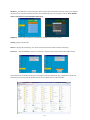
1
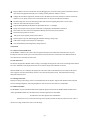
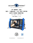
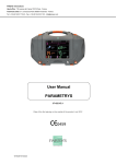
IP BUDDY+ IP & ANALOG TEST METER WITH VIDEO MONITOR Part number: ST-IP-TEST USER MANUAL v. 2.0 www.nacebrands.com www.securitytronix.com Thank you for purchasing the SecurityTronix IP BUDDY+ Analog and IP camera monitor with network tester! To use the IP BUDDY+ safely, please read the Safety Information carefully. This manual should be kept with the IP BUDDY+ for reference. Keep the serial number label for after-sale service within the warranty period. Please see the last page of the manual for warranty information. Batteries come disconnected to ensure they do not drain during shipment. Please connect the battery prior to powering on the IP BUDDY+. If you have any questions or problems while using the IP BUDDY+ camera tester, please contact our SecurityTronix technical support department at 1-800-688-9282, option 3, then option 2. Visit our website http://www.securitytronix.com for additional information. Table of Contents 1. Safety information ......................................................................................................................1 2. IP BUDDY+ Introduction .........................................................................................................1 2.1 General ..........................................................................................................................................1 2.2 Features ........................................................................................................................................1 2.3 Function .......................................................................................................................................2 2.3.1 Touch screen and OSD menu .................................................................................2 2.3.2 IP camera test ................................................................................................................2 2.3.3 Analog camera test......................................................................................................2 2.3.4 Video level meter .........................................................................................................2 2.3.5 PTZ controller (Activates analog video viewing and testing) ................3 2.3.6 Enhanced Color bar generator ..............................................................................3 2.3.7 12VDC 2A/5VDC 2A output power .....................................................................3 2.3.8 Audio testing ..................................................................................................................3 2.3.9 Cable tester .....................................................................................................................4 2.3.10 PTZ data analysis ......................................................................................................4 2.3.11 Digital Image zoom on the monitor .................................................................4 2.3.12 Video screen shot, record and playback ........................................................4 2.3.13 DHCP dynamic address assignment ................................................................4 2.3.14 Access the dynamic IP address ..........................................................................4 2.3.15 Multiple network IP Cameras Test ...................................................................4 2.3.16 IP address scan ..........................................................................................................4 2.3.17 PING Test ......................................................................................................................4 2.3.18 Port flashing ................................................................................................................4 2.3.19 PoE Test .........................................................................................................................4 2.3.20 LED flashlight..............................................................................................................4 2.3.21 WIFI .................................................................................................................................5 2.3.22 PoE power supply .....................................................................................................5 2.3.23 HDMI signal output ..................................................................................................5 2.3.24 Network bandwidth testing.................................................................................5 2.3.25 Cable Search ................................................................................................................5 2.3.26 Screen display rotates in 180 angle .................................................................5 2.3.27 FTP Server ....................................................................................................................5 2.4 Packing list ..................................................................................................................................6 2.5 Operational buttons and description of connections. ............................................7 3. Operation .....................................................................................................................................9 3.1 Installing the Battery .............................................................................................................9 3.2 Instrument connection..........................................................................................................9 3.2.1 IP camera connection.........................................................................................................9 3.2.2 Analog camera test ........................................................................................................... 10 3.3 OSD menu ................................................................................................................................. 10 3.3.1 PTZ (Activates analog video viewing and testing) ................................... 11 3.3.2 Color-bar generator (TV OUT) ........................................................................... 16 3.3.3 ONVIF ............................................................................................................................. 17 3.3.4 IP camera test ............................................................................................................. 21 3.3.5 IP address scanner ................................................................................................... 22 3.3.6 PING Test ...................................................................................................................... 23 3.3.7 Cable test ...................................................................................................................... 23 3.3.8 Cable search ................................................................................................................ 24 3.3.9 Port flashing ................................................................................................................ 24 3.3.10 Data monitor ............................................................................................................ 25 3.3.11 Media Player............................................................................................................. 25 3.3.12 Audio player ............................................................................................................. 26 3.3.13 LED lamp (Flashlight) .......................................................................................... 26 3.3.14 PoE in line Voltage test........................................................................................ 26 3.3.15 Calculator ................................................................................................................... 27 3.3.16 Browser ...................................................................................................................... 27 3.3.17 IP camera viewer ................................................................................................... 28 3.3.18 PoE power / 12VDC 2A and 5VDC 2A USB power output.................. 28 3.3.19 Application tools .................................................................................................... 29 3.3.20 Tool Folder ................................................................................................................ 32 3.4 System Settings ...................................................................................................................... 32 3.5 Update ........................................................................................................................................ 34 3.6 Audio test.................................................................................................................................. 34 3.7 HDMI output............................................................................................................................ 34 3.8 PoE power output ................................................................................................................. 35 3.9 12VDC 2A power output ................................................................................................... 35 3.10 USB 5VDC 2A power output.......................................................................................... 36 4. Specifications ............................................................................................................................. 37 5. SecurityTronix IP BUDDY+ Warranty ............................................................................ 38 1. Safety information ◆ The IP BUDDY+ is intended for use in compliance with applicable codes and laws. ◆ Do not expose to moisture. ◆ Do not drop. ◆ The tester should not be charged over 8 hours. ◆ The tester should not be used in an environment with any flammable gas or chemicals. ◆ Do not disassemble the IP BUDDY+ meter except to change the battery. ◆ Don’t use any chemical cleaning products to clean the test meter. Use a dry cloth. 2. IP BUDDY+ Description 2.1 General The 7 inch touch screen IP camera monitor and tester is designed for maintenance and installation of IP cameras and analog cameras as well as other security equipment. The 1024x600 resolution enables it to display network HD cameras and analog cameras in high resolution. The unit supports many ONVIF PTZ and analog PTZ control. The tester is also a great tool for Ethernet network testing. It can test PoE power voltage, PING, and IP address searching. You can use the blue cable tracer to locate individual connected cables from a bundle of cables. Test LAN cable for proper connection termination. Other functions include providing 24W PoE power to your camera, LED Flashlight, DC 12V 2A power output and much more. Its portability, user-friendly design and many other functions make the IP BUDDY+ an essential tool for all installers or technicians. 2.2 Features 7 inch 1024x600touch screen, easy to operate. ONVIF IP camera video testing. Compatible with H.264/MPEG4/MJPEG IP cameras, such as Dahua, HIKVISION, and ACTI. Built in Wi-Fi: receives video from wireless cameras or ONVIF cameras connected to the network. HDMI signal output,supports up to 1080P. Analog camera video display. Auto adapts and displays the video in NTSC/PAL formats. Supports more than 30 protocols such as PELCO-P, PELCO-D, and SAMSUNG. Video image digital zoom to view the image in greater detail. Snapshot function allows you to save the current image as a JPG file in the SD card. Video recording and playback. LED Flashlight. 4GB Micro SD card included. LCD screen with adjustable brightness/contrast/color/saturation. Enhanced Color bar generator: PAL/NTSC multi-system color bar video generator (Eight-system switchable, transmit/receive eight-system colorful images). PEAK video signal level, SYNC signal level, Color burst chroma level measurement: Test video signal attenuation Cable tracing by sending an audio signal. This enables the blue cable tracer to find the connected cable from a bundle of cables with an audio tone. Page.1. Ping test: PING is the most conventional network debugging tool; it is used for testing if the connected IP camera or other network equipment’s Ethernet port is working normally and the IP address is correct. In digital IP surveillance applications, if the IP camera’s IP address is not known; the device cannot be used. An IP address scan can quickly search for the connected IP camera or other network device’s IP address. The PoE voltage test can test for PoE voltage when a POE switch is supplying POE power to an IP camera. Cable test: Tests LAN cable sequence of wires. Supports RS232/RS485, The Baud Rate is adjustable from 600 ~ 115200bps. PTZ protocol analysis: Control protocol commands are displayed to check RS485 transmission. PTZ control: Pan, tilt & zoom, focus adjustment, IRIS Open/Close and set preset positions. DC12V 2A output power for cameras. PoE power output supplies power for PoE cameras. DC5V 2A power output for USB charging (No USB data exchange, voltage only) Audio input and output tests. Outputs an audio signal. 7.4V 48.1Wh Battery. Remaining battery charge indicator. 2.3 Function 2.3.1 Touch screen and OSD menu The IP BUDDY+ combines touch screen control and physical buttons. This combination makes the tester very user friendly. The test meter allows you to move the function icons from the tester’s main menu to the APPS tool folder or move them back to customize the main menu. 2.3.2 IP camera test The device is designed for ONVIF IP camera testing. It can display the image from an IP camera and change the IP address. The 7 inch 1024x600 screen display allows the user to view the image with a sufficient screen size. With the ONVIF tool, you can display the image from an IP camera and use the PTZ functions. Currently the IP camera tester supports more than 30 brands’ IP cameras, such as most SecurityTronix, ACTi, Dahua, Hikvision, Samsung, Honeywell and many more. 2.3.3 Analog camera test Displays an analog camera image on the 7 inch 1024x600 LCD screen display. Supports PAL & NTSC formats. The LCD screen's back light brightness, video image brightness, contrast and color saturation are all adjustable. 2.3.4 Video level meter The IP BUDDY+ can perform NTSC and PAL video amplitude signal measurements for PEAK to PEAK and SYNC levels. Video signal PEAK to PEAK level: For NTSC format, the video signal level is 140±15IRE For PAL format, the video signal level is 1000±200mV If the level is too low, it will cause the image to lose quality and limit the distance it will travel over cable. If the level is too high, it will lead to wash out of the image. Page.2. SYNC level: Testing the amplitude of the video sync pulse to verify if the video level is correct. For NTSC format, the SYNC level is 40 ± 5IRE For PAL format, the SYNC level is 300 ± 35mV If the level is too low, it will cause the image to not frame out properly. If the level is too high, it will lead to a poor quality image. COLOR BURST level: Testing the color burst level will determine if the burst signal is sufficient to trigger the displays color producing circuit. Burst will diminish in amplitude over longer cable runs and can get fall below the threshold for the video display to show a color image. For NTSC format, the Chroma standard level is 40 IRE For PAL format, the Chroma standard level is 280mV If the Chroma level is too low, the color will not be as deep, and some details of the image will get washed out. If the Chroma level is too high, there will be spots on the image. If the coaxial cable is too long, it will reduce the chroma level. 2.3.5 PTZ controller (Activates analog video viewing and testing) Displays and allows for analysis of analog video and controls Pan/tilt/zoom function of PTZ analog cameras. For PTZ testing, setup the controlling parameters from the meter to match those of the camera: e.g. PTZ protocol (PELCO-D, etc.), communication port (RS-485, etc.), baud rate, PTZ camera ID and pan/tilt speed. 2.3.6 Enhanced Color bar generator The tester sends out color bars via its BNC output to the monitor. This is used to test for a problem in the cable going from the camera back to the monitoring area. 2.3.7 12VDC 2A male power output port and 5VDC 2A USB power port The unit can power a camera with its 12VDC 2A male power output. Also included is a built in 5VDC 2A power output port used to charge USB devices. NOTE: This USB port is for charging only and has no ability to transfer data. 2.3.8 Audio testing Test the audio from mic level input devices. Connect the tester and mic level device with the audio cable. Supports audio recording and output. Consult your local laws and regulations on recording audio and using audio devices. In the United States of America and all individual states thereof, there are federal and state laws that limit your ability to monitor and / or record audio. These laws expose you to the risk of criminal prosecution and potentially give an injured party a civil claim for money damages against you. Page.3. 2.3.9 Cable tester Connect a LAN cable or a telephone cable from the IP BUDDY+ unit to the included blue remote cable tester. The unit will test for connection status, cable type and the status of each wires conductivity will be displayed. 2.3.10 PTZ data analysis Test the PTZ control command data to diagnose any errors or to ensure there is a sufficient RS485/RS232 data transmission. The unit receives the control protocol code (PELCO-D, etc.) from a PTZ keyboard or a DVR with a RS485/RS232 interface. The unit will display 16 hexadecimal codes such as: PELCO-P:A0 00(Add) xx xxxxxx AF xx PELCO-D:FF 01(Add)xx xxxxxxxx 2.3.11 Digital Image zoom on the monitor Set image zoom up to 4X to get a closer look at all the image detail. Supports analog and many IP cameras. 2.3.12 Video screenshot, record and playback Capture the video image displayed and save as a JPEG file. You can also record and save the current video to the SD card.. 2.3.13 DHCP dynamic address assignment Built in DHCP server: Dynamically assign IP address for the IP camera or network device. 2.3.14 Access the dynamic IP address The IP tester can directly access a dynamic IP address assigned from its DHCP server and use it as the tester’s IP address. No need to set a IP address manually. 2.3.15 Multiple network IP Cameras Test Supports Multi- segmented Static IP address setting which can simultaneously test different segments of IP network cameras. 2.3.16 IP address scan The IP address scan can quickly search for connected IP cameras or another network device IP address. 2.3.17 PING Test PING is the most conventional network debugging tool; it is used for testing if the connected IP camera or other network equipment is working normally and the IP address is correct. 2.3.18 Port flashing The tester will send signals to make the connected PoE port flicker at a set frequency. This will enable the installer to easily and quickly find the connected port for an Ethernet cable. 2.3.19 PoE Test Test the PoE voltage from a PoE switch. The unit will clearly display the voltage for each wire in an Ethernet cable. 2.3.20 LED flashlight Press the LED On/Off button to use the LED flashlight. Page.4. 2.3.21 WIFI With built in WIFI, you can view the video from a wireless camera (ONVIF or customized camera) or connect to a Wireless network. 2.3.22 PoE power supply Supports PoE 802.3at power at 48V and up to 24W. 2.3.23 HDMI signal output The HDMI output port supports up to a 1080p 60Hz resolution output. 2.3.24 Network bandwidth testing The network bandwidth test needs two IP BUDDY+ meters to test bandwidth: one as a transmitter, the other as a receiver. 2.3.25 Cable Search Cable identification by use of an audio signal. This function enables the blue cable tracer to find the connected cable from a bundle of cables with an audio tone. 2.3.26 Screen image rotates 180 degrees You can manually rotate the display 180 degrees using the settings. . 2.3.27 FTP Server Start the tester’s Wi-Fi or connect the tester’s LAN port to the network. Once the tester is online, start its FTP Server and directly access files from the tester’s SD card. This also allows for the user to upgrade the tester firmware. Page.5. 2.4 Packing list 1) IP BUDDY+ video monitor and IP tester 2) 12VDC 2A charger 3) Combination cable identifier and network cable tester 4) Polymer lithium ion battery (7.4VDC 6600mAh) (typically not plugged in) 5) 3 foot BNC test cable 6) 18 inch RS485 test cable with alligator clips 7) 3 foot camera powering cable 8) 18 inch 3.5mm audio microphone or speaker cable with alligator clips 9) Carrying case and hanging strap with front accessory pouch 10) IP BUDDY+ hands free monitor support neck strap with adjustable angle view supports 11) User’s Manual 12) 4GB SD card 13) 18 inch BNC to alligator clip test cable Page.6. 2.5 Operational buttons and description of connections. 1 Power button: Hold more than 2 seconds, turns on or off the device. Quickly press for sleep mode 2 Menu key 3 4X Zoom digital image display. (Optional) OTDR start or stop. 4 Video record 5 Snapshot 6 Far focus: Focus images at a distance 7 Near focus: Focus close range images 8 TELE: zoom in on the image 9 WIDE: zoom out to the image 10 Open or set parameter. Open the camera iris aperture 11 Close Return: Return or cancel menu parameters. Close the camera iris aperture 12 Confirm setting key 13 Up arrow to scan through options. Tilt a PTZ camera upward 14 Down arrow to scan through options. Tilt a PTZ camera downward 15 Left arrow to scan through options. Pan a PTZ camera left 16 Right arrow to scan through options. Pan a PTZ camera right Page.7. Top interface Bottom interface 17 Multimeter inputs (Optional) 18 Charging indicator 19 RS485/RS232 data transmission indicator 20 RS485/RS232 receive indicator 21 Battery life indicator 22 Fiber cable testing visible red laser source. Emits dangerous light!!! Do not look at directly. (Optional) 23 12VDC 2A power output for testing cameras or other devices 24 SDI input (Optional) 25 Analog video signal input(BNC interface) 26 27 28 29 Analog video signal output(BNC interface)or cable tracer interface connection. Optical power meter input (Optional) RS485 Interface: RS485 bi-directional connector for a PTZ or other RS485 communication RS232 Interface: RS232 bi-directional connector for a PTZ or other RS232 communication 30 LED “flashlight” lamp 31 TDR cable input (Optional) 32 HDMI output connector (mirrors unit display image) 33 Micro SD card slot (comes with 4GB, supports up to 16GB) 34 UTP cable port: UTP cable tester port or Cable tracer port 35 Audio output and earphone interface (3.5mm) 36 Audio input (3.5mm) 37 PSE power sourcing equipment. Tests PoE voltage. 38 PoE power supply output or LAN test port (Use to test PoE or non-PoE IP camera) Page.8. 39 USB 5V 2A power output (used only for power, not data) 40 12VDC 2A charging input 41 12VDC 2A power output 3. Operation 3.1 Installing the Battery The tester has a built-in lithium ion polymer rechargeable battery. Prior to the use of the unit, the battery cable connection behind the battery door needs to be connected and the unit fully charged for no more than 8 hours prior to use. Pressing the key for two seconds will power on or off the tester. Notice:Please use the original adapters and cables of the device! When the battery icon is full or the charge indicator turns off automatically, the battery charging is complete and the charger needs to be unplugged. Notice: When the Charge Indicator turns off, the battery is approximately 90% charged. Do not charge for more than one hour after this indicator turns off. Notice: Hold the key for several seconds until the unit restarts to restore the factory default settings. Warning: RS485 and RS232 Instrument communication ports are not permitted to exceed circuit voltage over 6V, otherwise it will damage the tester. 3.2 Instrument connection 3.2.1 IP camera connection Power an IP camera with an independent power supply and then connect the IP camera to the IP BUDDY+'s LAN port. If the link indicator of the tester’s LAN port is green and the data indicator flickers, it means the IP camera and the IP BUDDY+ are communicating. If the two indicators don’t flicker, check if the IP camera is powered on or the network cable is not functioning properly. Page.9. Note: If the IP camera requires PoE power, then connect the IP camera to the IP BUDDY+ meter’s LAN port . The tester will supply PoE Power for the IP camera. Click on the icon labeled POE to turn the PoE Power off or on. Warning:PoE switch or PSE power sourcing equipment can only be connected to the meter’s “PSE IN” port, otherwise it will damage the tester. 3.2.2 Analog camera test (Press the PTZ icon to activate analog video viewing and testing) (1) Connect the camera's video output to the IP BUDDY+'s BNC VIDEO IN. The image will display on the tester after pushing the PTZ icon. (2) IP BUDDY+'s “VIDEO OUT” BNC connector can connect to the Video input of a monitor. (3) Connect the camera or PTZ RS485 controller cable to the tester's RS485 interface, (Note positive and negative connection of the cable must be connected with proper polarity to operate). 3.3 OSD menu Select an icon to open the app. To exit, press the key. To move an app icon to the “APPS” folder, press and hold until the “move to apps directory” appears on the screen then press OK to move it or Cancel. Page.10. 3.3.1 PTZ (Activates analog video viewing and PTZ camera testing) For Analog camera testing and PTZ control, click this icon: Click the top menu bar icon to enter the video waveform testing function (PEAK level, SYNC level, and COLOR BURST measurements) Additional functions are on the right side of the PTZ app Toolbar. These additional functions include “Photo”, “Snapshot”, “Record”, “Playback”, “PTZ” and “Set” Tap the screen twice in rapid succession to zoom in on the video image. Click or press the key to exit this application. (1) PTZ controller parameter setting Select and click on “PTZ” to enter the PTZ settings page: Settings available are: A. Protocol Use the up and down arrow keys or tap the word “Protocols” to move the yellow cursor to “protocols” and activate this setting. This allows for setting a matching communication protocol from the IP BUDDY+ to the PTZ camera. (Most SecurityTronix PTZ cameras use PELCO-D) Page.11. B. Port Select the communication port type for the PTZ camera controller (RS232/485). This is the external port used to connect to the camera. C. Baud Rate Select the baud rate to match the baud rate of the PTZ camera. (150 – 115200 bps) D. Address Set the numerical address ID to match the ID of PTZ camera (0~254) E. Pan speed: Set the desired pan speed of PTZ camera (0~63) F. Tilt speed: Set the desired tilt speed of PTZ camera (0~63) G. Set position Set and save preset position number (1~128), H. Call position Call the previously saved preset position number (1~128) For all settings, once set click “OK” to save, TIP: You can call up the OSD menu on most SecurityTronix PTZ cameras’ with Call Position 95. Double check the protocol, address, interface and baud rate. All must be consistent with the PTZ camera or it will not properly communicate. Using the touch screen to control PTZ camera movement: Tap left, right, upward or downward on the video image to move the PTZ camera in a desired direction. Stretch two fingers outward or inward on the touch screen to zoom the image in or out. PTZ Control: The keys or control the pan and tilt direction The keys or controls opening and closing the iris manually The keys or adjusts the focus manually The keys or manual zoom control (2) Video and storage settings Click the “Set” icon to enter the mode for setting analog video image brightness, contrast and color saturation. You can also set a file storage location after taking a snapshot or making a Recording. When selecting to store a file you can manually name the file. Page.12. (3) 4X Zoom image display and Video out When an image is displayed, press the button to enter the digital zoom mode, press it again to quit. Using two fingers on the touch screen, move outward or inward to zoom in and out on the image. When the image is enlarged, click left, right, upward or downward to move the image around. If you prefer not to use the touch screen, press the key to zoom out and press the key to zoom in. Press the upward and downward keys to move the image around. (4) Snapshot Click the “Snapshot” icon to take a picture and save the current video frame to the SD card as a JPEG file. If the unit is set to the manual mode an “Input Name” pop up box will appear and you can enter a title for the snapshot. If the unit is set up to automatically set file names, this box will not pop up. (5) Video record When you click the “Record” icon, video starts recording. A red recording icon appears on the screen and begins to flash and a timer appears indicating the time elapsed for the video. Click on the “Record” icon again to stop recording and save the video file to the SD card. Page.13. (6) Photo When you click the “Photo” icon, it displays a gallery of saved still images on the screen. Select the thumbnail image you would like to view. Double-tap the image you want to view to make it full screen. Double-tap it again to return to the gallery. To rename or delete an image, click and hold on the file until this screen below appears: Click to close and return to the PTZ controller screen. (7) Recorded video playback Click the “Playback” icon to view your recorded videos. Tap on the video file image you want to watch. Page.14. To rename or delete a video, click and hold on the file until this screen appears: (8) Video level meter Click the icon to open the Video Level meter. The IP BUDDY+ meter can perform both NTSC and PAL video amplitude signal measurements for PEAK to PEAK and SYNC levels. When an analog signal is fed into the meter, the tester displays the measurements on the bottom left corner of the screen. While in PAL format, the unit will be mV, While in NTSC format, it will be IRE. NTSC PAL Video signal level 140±15IRE Chroma level( COLOR BURST) 40±5IRE SYNC signal level 40±5IRE Video signal level 1000±200mV Chroma level( COLOR BURST) 300±35mV SYNC signal level 300±35mV Page.15. Video signal PEAK to PEAK level: For NTSC format, the video signal level is 140±15IRE For PAL format, the video signal level is 1000±200mV If the level is too low, it will cause the image to lose quality and limit the distance it will travel over cable. If the level is too high, it will distort the image. SYNC level: Tests the amplitude of the video sync pulse to verify if the video level is correct. For NTSC format, the SYNC level is 40 ± 5IRE For PAL format, the SYNC level is 300 ± 35mV If the level is too low, it will cause the image to not frame out properly. If the level is too high, it will lead to a poor quality image. COLOR BURST level: Testing the color burst level will determine if the burst signal is sufficient to trigger the displays color producing circuit. Burst will diminish in amplitude over longer cable runs and can get fall below the threshold for the video display to show a color image. For NTSC format, the Chroma standard level is 40 IRE For PAL format, the Chroma standard level is 280mV If the Chroma level is too low, the color will not be as deep, and some details of the image will become lighter. If the Chroma level is too high, there will be distortions on the image. If the coaxial cable is too long, it will reduce the chroma level. 3.3.2 Color-bar generator (TV OUT) Click on the icon to open the Color-bar generator (TV OUT). The IP BUDDY+ meter sends the color bars via its VIDEO OUT BNC port. Click on the “PAL” button to switch between PAL or NTSC output formats. Select the different color bar choices at the bottom. To make the color bars full screen, double tap on the image. This is used to test for a problem in the network of cable, connectors, and active processing equipment going from the camera back to the monitoring area. Page.16. 3.3.3 ONVIF The Open Network Video Interface Forum (ONVIF) app is used to connect to ONVIF compliant IP cameras only. If the IP camera's video stream is MPEG4, use the ONVIF (SD) mode. If your IP camera's video stream is H.264, use ONVIF HD (High Definition). (SecurityTronix IP cameras use ONVIF HD with H.264) Click the icon to enter the ONVIF app. Then tap either the ”ONVIF” icon is for SD mode (MPEG4) and the “ONVIF HD” icon is for HD mode (H.264). Once you select ONVIF SD or HD mode, the meter automatically scans different network segments for ONVIF cameras. It lists the camera name and IP address on the Device List. If no cameras appear under the device list, try clicking on the Refresh button. If your IP camera does not appear after scanning the network, you can manually add an IP camera by clicking on the “Add” button on the bottom left. The URL address should be identical to the ONVIF camera service address. (With your camera’s IP address entered into the URL). Click OK to add the manually entered camera and then click the “Refresh” button. Page.17. Click the newly displayed ONVIF camera on the “Device List“. The tester will show the IP camera’s relative information and settings. After selecting your ONVIF camera, enter the IP camera’s username and password at the top left of the screen and then click “Login”. After you log in, click on the camera under “Device List”. Once you are connected to the camera, the following options become available: Identification, Time Set, Maintenance, Network Set, User Set, Live Video, Video Streaming, Image Set and Profiles. Live Video: Click “Live Video” to view the live video feed from the IP camera. To make the image full screen, double tap on the video. Stretch two fingers outward or inward on the touch screen to zoom the image in or out. While in the “Live video” menu, click “Video Menu” at the top right of the image to access the following tools: Snapshot, Record, Photo, Playback, PTZ and Settings. Page.18. ONVIF PTZ control: Tap the image in the direction you want the PTZ camera to move. Tap the left side of the image to move left, right to go right, up to go up and down to go down. Compatible IP PTZ cameras will rotate accordingly. PTZ rotation direction is displayed on top left corner of the image. Zoom in on an image: Press the key to enter the zoom mode. Press it again to exit zoom mode. When the image is enlarged tap left, right, up or down on the image to move the whole image on the screen. IP camera video settings: Click “Video Set” to enter the IP camera’s encoder and resolution settings. Make the desired changes and click “OK “to save. Image setting: Click “Imaging Set” to adjust image brightness, saturation, contrast, sharpness and backlight compensation mode. Page.19. Network settings: Click “Network Set“ to change the IP address settings. NOTE: Some cameras are not fully ONVIF compliant and cannot support changing their IP address, so there is no change after saving. Snapshot:Click “snapshot” to save the current image as a JPEG file on the SD card. Record:When you click the “Record” icon, video starts recording. A red recording icon appears on the screen and begins to flash and a timer appears indicating the time elapsed for the video. Click on the “Stop” icon to stop recording and save the video file to the SD card. Set:Click on the “Set” icon to change Snapshot and Video recording file name settings. You can set Auto storage, which sets filenames by time or set manual storage. Click “Sure” to save file name settings. Page.20. Playback:Click the “Playback” icon to view saved videos. Double click the video you want to play. Click to return to the last menu. To rename or delete a photo, click and hold on the file until this screen appears: 3.3.4 IP camera test The “IPC Test” app is used for IP cameras that are fully integrated by name with the IP BUDDY+ meter. If the IP camera's video stream is MPEG4, use the IPC Test (SD) mode. If your IP camera's video stream is H.264, use IPC HD (High Definition). (SecurityTronix IP cameras use IPC HD with H.264) Click the icon to enter the IPC Test App. Note:Currently, the IPC Test App only supports some brands’ specific IP cameras; these include specific models made by ACTI, AXIS, Dahua, Hikvision, Samsung, SecurityTronix, and many more. If the camera is not fully integrated, please use the ONVIF or RTSP apps. Page.21. IPC Test Interface: Local IP: This is the tester’s IP address. Click “Edit“ to enter “IP setting“ and change the tester ‘s IP address settings. IP camera type: Click on the IP Camera type to select the Manufacturer and model number of the integrated IP camera. IPC Cameras IP: Enter the IP camera’s IP address manually or click “Search” to auto-scan for the IP camera’s IP address. It is better to directly connect the IP camera to the tester so the search results will only display the camera’s IP address. If the tester is connected to a PoE switch, it will find and display several IP address. IPC User Name: Enter the IP camera’s user name. IPC Password: Enter the IP camera’s password. IPC Port: When you select the IP camera type, it will default the camera’s port number and doesn’t need to be changed. After all settings are completed, click “Enter” to view the live video. Once you are viewing video on the IPC Test app, you will see the “Video Menu” icon on the top right. This button will give you access to Snapshot, Record, Photo, Playback, PTZ, and Set. Please refer to the ONVIF section to use these functions. (pg. 18) 3.3.5 IP address scanner Connect your network cable to the LAN port of the IP BUDDY+ meter and then click the icon to open the IP address scanner. Set your IP address search range by changing the Start and End IP addresses. Click the “Start” button to scan the IP address range. You can also input an IP address in the Port Number Scan to scan for open ports. Page.22. 3.3.6 PING Test PING is the most conventional network debugging tool; it is used for testing if the connected IP camera or other network equipment’s Ethernet port is working normally and the IP address is correct. Connect a network cable to the LAN port and click the icon to open the PING tool. You can set your LOCAL (native) IP address, Remote IP address (e.g. IP camera), Packet count, Packet Size, Packet time and Timeout. Press “Start” to start pinging. If the IP camera or network device is not configured properly or not plugged in, it will say “Destination host unreachable,” or have 100% packet loss. If the tester connects to the device, the send and receive packets will have a 0% packet loss. 3.3.7 Cable Test Click the icon to open the cable tester app. Connect a Network cable from the IP BUDDY+ unit’s UTP/SCAN port to the included blue cable identifier and network cable tester combo device. The unit will test for connection status, cable type and the status of each wire’s conductivity will be displayed. Page.23. 3.3.8 Cable Search Connect a BNC cable to the “Video Out” port or connect a network cable to the UTP/SCAN port. Click the icon to open the Cable Search app. To switch between the different audio tones, select a number on the screen. Use the blue Combination cable identifier and network cable tester’s copper pointer to touch all the cables in the bundle you are searching at the other end. The cable that gives off the loudest tone is the cable connected to the tester. Press the + or – buttons on your blue cable identifier to adjust the volume. Note:Install two AAA batteries in your blue Cable Identifier. Note:While the cable tracer is receiving the audio signal from the tester, it may be induced into adjacent or crossing cables; however, the cable that makes the loudest noise is the one that’s connected to the meter. 3.3.9 Port flashing Connect a network cable to the meter’s “LAN” port, click the icon to open the Port Flashing app. Click “Start”. The IP BUDDY+ sends a unique signal to make the connected LAN port of the switch flash. Page.24. 3.3.10 Data monitor Click on the icon to use the Data monitor. Click “Setting” to choose the baud rate of RS485/RS232; this must match the DVR, Control keyboard, or other device under testing. The device sends its code to the tester. If the code can be read, the code will show on the upper right part of the screen. To clear data from the code field, press the key. 3.3.11 Media Player Click the icon to bring up the Media Player. The Media player can browse video and image files. It supports the video formats of MP4, H.264, MPEG4, and MKV. The IP BUDDY+’s recorded files can play directly via the Media player. The Media player will automatically display the video files from the SD card. Click on the desired file to play. Click RETURN to exit. To rename or delete an existing file, press the file name for a few seconds until the screen below appears. You can then rename or delete the file by pressing the desired option. Page.25. 3.3.12 Audio Player Click the icon to enter the audio player. The audio player only supports MP3 format Audio files. 3.3.13 LED lamp (Flashlight) Click the icon to activate the LED lamp. While in the flashlight app, click the red button to turn on the LED lamp. Press it again to turn it off. If you don’t press the red button to shut off the lamp and press the button to exit the app, the lamp will stay on. Click the Time Setting button to set a timer that will shut off the lamp. 3.3.14 PoE in line Voltage test Click the icon to enter the PoE voltage in line measurement app. Page.26. Connect a network cable from a PoE switch to the IP BUDDY+’s PSE IN port. Connect an IP camera or other PoE using node to IP BUDDY+’s LAN port, the PoE voltage and the cable’s pin connection status show on the screen. Note:This test if for measuring the voltage being drawn by the PoE node and the IP BUDDY+ must be between the PoE switch and the PoE node for this test to work. Note: The PoE switch must be connected to the PSE IN port. The powered device such as IP camera or other PoE node must be connected to the LAN port. Note: Do not connect PoE power supply equipment (such as a PoE switch) to the tester’s UTP/SCAN port; otherwise it will damage the tester. 3.3.15 Calculator Click the icon to open the Calculator app. 3.3.16 Browser Click the icon to open the Browser app. Type in the camera’s IP address and press “Go” to access the IP camera’s interface. NOTE: You will not be able to view live video in the web browser. For viewing video, use the IP BUDDY+ live camera view apps. The IP camera and IP Buddy+ must be on the same network segment for the browser to interface with the camera. If they are not in the same segment, click the button or press “RETRUN” to exit. Open the “Settings” app from the main menu to change the IP Buddy+’s network settings to match those of the IP camera. Page.27. 3.3.17 IP Camera viewer In addition to the ONVIF app or the IPC Test app, you can use one of the mobile apps in the IPC Viewer folder. Click the “IPC Viewer” icon to open the mobile apps folder. Select your IP camera’s corresponding mobile app to connect to it. Note:The Video Management apps are third party applications. SecurityTronix does not support these apps nor make any usage claims. We do not assume any legal liability. Click on the “update” icon at the top of the IPC Viewer screen to check for mobile app updates. 3.3.18 PoE power / 12VDC 2A and 5VDC 2A USB power output When the tester is turned on, the 12VDC and 5VDC power output functions are automatically turned on. If the IP Buddy+ is turned off, the 5VDC USB can still be used to power an external USB device. To use the PoE Power Output function, click on the icon and change the switch “ON” or “OFF”. The IP camera needs to be connected to the LAN port before you turn PoE Power on. If the IP camera supports PoE, the PoE power is delivered via pins 1, 2, 3, and 6 on the LAN port. The IP Buddy+ will display “48V ON” at the top of the screen when the POE power is still on. Page.28. Note: 1. Don’t input power into the “DC12/2A OUTPUT” port. 2. Make sure you plug in your IP camera to the LAN port prior to turning on PoE power. 3. Before turning on the PoE power output, please make sure the IP camera supports PoE power. Otherwise it may damage the IP camera. 3.3.19 Application tools Click the icon to open the Application Tools folder. This folder contains useful apps such as Audio Recording, DHCP Server, Network test, Notepad, Link monitor and RTSP Player. Audio Recorder: Connect an audio device to the IP Buddy+’s audio input port. Click the icon to enter the Audio Recorder app. Click the red button to stop, and the unit will prompt you to save the recording. Network test (Ethernet bandwidth test) To use the Network tester, you will need two IP BUDDY+ testers. One is used as a Server and the other as a Client. Both devices must be on the same network segment in order to communicate. Click the app. Page.29. icon to open the Network Tester a). Start the server:Click “Start Server” button to use the tester as a Server. It will display its IP address at the top of the screen. b). Start send packet test:Using the other IP BUDDY+, type in the Server's IP address at the top right corner of the screen. This app is used to send packets for network speed testing. Click the “Start” button to send the packets and start testing. Network bandwidth testing can also be tested with a computer using compatible network bandwidth testing software. DHCP server: Click on the DHCP icon to open the DHCP server app. Select the “Start” check box at the top and make any desired changes to the network settings. Click “Save” to start assigning dynamic IP addresses for IP cameras and other networked devices. Click the “Refresh” button to check your Client list. Page.30. Notepad: Click on the Notepad icon to open the Notepad app. Click the “Save” key to save the contents Link monitor : Click the icon to open the Link Monitor app. This app is used to see if an IP address is occupied by other network devices. This will avoid new address conflicts. Click “Add” and enter the desired IP address. To test different network segments, click the “Settings” icon on the main menu and go to IP Settings and make the desired changes. Once the desired IP addresses are added to the Link Monitor list, click “Start”. If the IP address status shows a check mark the IP address is occupied. If the IP address status shows an X the IP address is available. Click “Stop” to stop the testing. RTSP Player : The RTSP Player app will allow you to view the RTSP video stream from an IP camera. If you were unable to view your camera via the ONVIF or IPC Test apps, it is possible your camera will have an RTSP stream and you can view live video. From the main menu, select the “APP Tool” folder and then select the “RTSP Player” to open the app. If the IP camera uses MJPEG, select the RTSP icon. If the IP camera uses H.264, select the “RTSP HD” icon. Local IP: This is the IP Buddy+’s IP address. RTSP Add: This is where you can manually enter the IP camera’s RTSP URL or click on Search to search the network for cameras that use an RTSP stream. IPC Username: Enter the IP camera’s user name. IPC Password: Enter the IP camera’s password. Once you have entered all the necessary information, select Enter at the bottom left to view the RTSP stream. NOTE: IN THE EVENT THE IP BUDDY+ DOES NOT AUTO DETECT THE RTSP STREAM, REFER TO THE SPECIFIC CAMERA MANUFACTURER FOR THE SPECIFIC RTSP STREAM URL. YOU MAY FIND THIS ON LINE WITH A SEARCH OF THE CAMERA MODEL NUMBER AND THE WORD RTSP. Page.31. 3.3.20 Tool Folder Click the icon to open the Tool Folder. You can move desktop icons into the Tools Folder by pressing on the icon for a few seconds until the screen below appears: You can also move an icon back to the desktop by pressing on the icon for a few seconds until it asks you if you want to move the icon back to the Desktop. 3.4 System Settings Click the icon to enter the System Settings Menu. Language:Select your desired language: English, Chinese, Italian or Polish. Date/Time:Set the time and date of the IP Buddy+. IP Settings: Manually set the IP address, Subnet Mask, Default Gateway and DNS address or select “Dynamic allocation” to use DHCP. To test multiple network segments, click “Advanced” and then click “Add” to enter another IP address for the IP Buddy+. After setting an advanced IP address (refer to the photos above), the unit can test two network segments (192.168.0.0) and (192.168.1.0). Page.32. WLAN Net:Turn WiFi off or on by pressing the “Open the wifi” button. Once WiFi is turned on, it will scan for wireless networks in your area. Select the desired wireless network SSID and enter your password to connect. The IP BUDDY+ meter is only known to work with WPA2-PSK security. Brightness:Set the desired brightness of the IP Buddy+ and adjust the sleep time settings. Volume:Change volume levels. SD Card:Displays SD Card Capacity. You can also format the SD card or unmount it before removing it. FTP server:Once the IP BUDDY+ connects to a network, a computer can be used to read the SD card files via FTP. Start the FTP server and then input the tester’s FTP address in the PC’s address bar. (ftp://ipaddress:2121) This will enable the PC to read, copy and edit the files from the SD card without the use of SD card reader. Page.33. Version information:This displays the version information for each application. Screen display rotation:Click on “Screen Rotation” to flip the IP Buddy’s display 180 degrees. This function is very convenient for the user to connect the LAN cable on the bottom of the unit without having to flip the unit itself. PTZ address scan :You can toggle the PTZ Address scan off or on before entering the “PTZ controller” app. This needs to be turned on in order to use the PTZ Scan feature of the PTZ app. Turn off option:If you select “Fast turn off”, the tester will shut down faster but data will not saved. To avoid unnecessary problems, it is recommended not to use the “Fast turn off” option. 3.5 Update Click the icon to open the Update menu. Select “Local Update” to update via the SD card or select “Online Update” to check for updates on the internet. If there are applications that need updating, the applications will be displayed on the screen. Click the relevant applications to update them to the latest version. 3.6 Audio test You can test the audio input from audio pickup devices by connecting the audio pickup device to the IP Buddy+ with the supplied audio cable. 3.7 HDMI output The built in HDMI output port can output live video from an analog or IP camera, recorded files, media files and images to HDTV monitors. Connect an HDMI cable from the IP Buddy+ to an HDTV monitor at any time. It supports up to 1080P resolution. Page.34. 3.8 PoE power output The IP Buddy+ supports PoE (Power over Ethernet) output to an IP camera via the LAN port. Data transmission and 48VDC use the network cable’s 1, 2, 3, and 6 pins to deliver power. If the IP camera supports PoE, you can directly connect to the camera without the use of an external power supply. Note: Please make sure a network cable is connected to the IP Buddy+’s LAN port ONLY. Before using the PoE power output, please make sure the IP camera supports PoE power, otherwise it will damage the IP camera. 3.9 12VDC 2A power output When the IP Buddy+ is turned on, the 12VDC power output ON by default. The smaller end of the supplied converter cable connects to the tester’s DC12V/2A OUTPUT and the other end connects to the camera’s power input. Note: a. Don’t input any power into the “DC12/2A OUTPUT” port of the tester. Such damage will void the warranty. b. The IP BUDDY+’s power output capacity is 2A. If the IP camera uses more than 2A, the tester will automatically enter a protection mode. Disconnect all cables from the tester and reboot it to resume using the tester. c. Make sure the tester has a sufficient charge otherwise the tester will not able to provide enough output power. Page.35. 3.10 USB 5VDC 2A power output When the tester is turned on, the 12VDC and 5VDC power output functions are automatically turned on. If the IP Buddy+ is turned off, the 5VDC USB can still be used to power an external USB device. NOTE: The USB port is for power only and not data. Page.36. 4. Specifications – For more detailed inquiries, please call SecurityTronix tech support: 1-800-688-9282, option 3 and then option 2. Model Display Network port WIFI IP camera type ST-IP-TEST (IP BUDDY+) Analog & IP Test Meter 7 inch capacitive touch screen , resolution 1024x600 10/100M auto adjust,RJ45 Built in WIFI: Allows you to connect to a wireless network and view IP cameras ONVIF,ONVIF PTZ, SecurityTronix, Dahua IPC-HFW2100P, Hikvision DS-2CD864-E13, Samsung SNZ-5200, Tiandy TD-NC9200S2, Kodak IPC120L, Honeywell HICC-2300T, RTSP Viewer Analog Video test 1 channel BNC Input & 1 channel BNC Output , NTSC/PAL (Auto adapting) Video level meter PEAK video signal level, SYNC signal level, COLOR BURST chroma level measurement Zoom Image Supports Analog and IP camera image zooming & movement Snapshot, Video record and Capture still images and record live video. Media player will view photos and playback video playback HDMI output 12V/2A power output USB 5V power PoE power output Audio test PTZ control Color bar generator UTP Cable tester 1 channel HDMI output,supports up to 1080p Outputs 12VDC 2A to power camera 5VDC 2A power output only, no data 48V PoE power output. Max power 24W 1 channel audio signal input and 1 channel audio signal output to connect headphones Supports RS232/RS485 control, Baud rates 600-115200bps; ONVIF PTZ control Output one channel PAL/NTSC color bar via BNC Out or HDMI out to test monitors Test UTP cable connection and pin configuration Data monitor Captures and analyzes the hexadecimal data from controlling devices Network test IP address scan, link scan, and Ping test. Quickly search the for IP camera’s IP address on your network Cable search Find a connected cable from a bundle of cables using audio tones PoE/PSE voltage test Measures PoE switch voltage and displays pin configuration POWER Power supply Battery Rechargeable (2) 12VDC 2A power output ports; 5VDC power output; PoE Power output Included 7.4V Lithium polymer battery, 6500mAh After charging 7~8 hours, normal working time is 16 hours Parameters Operation setting Auto off Temperatures Humidity Dimensions and Weight Capacitive touch screen and real keys. Languages include English, Italian, Polish & Chinese Selectable between 1-30 minutes -10℃ ~ +50℃ 14°F ~122°F 30% ~ 90% 231mm x 172mm x 52mm / 1.26Kg 9 1/8 in x 13/16 in x 2 1/16 in 2 lbs. Page.37. SECURITYTRONIX 2-Year Limited Warranty IP BUDDY+ Securitytronix. (The "Company") warrants to the Original Purchaser that the IP BUDDY+ meters are free from defects in workmanship or material under normal use. This warranty starts on the date of shipment of the hardware to the Original Purchaser. During the warranty period, the Company agrees to repair or replace, at its sole option, without charge to Original Purchaser, any defective component in the IP BUDDY+ series meters. To obtain service, the Original Purchaser must return the IP BUDDY+ meter to the Company properly packaged for shipping. All defective products must be returned to the Company within thirty (30) days of failure. Products must be returned with a description of the failure and Return Merchandise Authorization (RMA) number supplied by the Company. To receive a RMA number and a return shipping address on where to deliver the hardware, call (610) 429-1821. The shipping, and insurance charges incurred in shipping to the Company will be paid by Original Purchaser, and all risk for the hardware shall remain with the Original Purchaser until such time as Company takes receipt of the hardware. Upon receipt, the Company will promptly repair or replace the defective unit, and then return said unit to Original Purchaser, shipping prepaid. The Company may use reconditioned or like-new parts or units, at its sole option, when repairing any hardware. Repaired products shall carry the same amount of outstanding warranty as from original purchase. Any claim under the warranty must include dated proof of purchase or invoice. In any event, the Company's liability for defective hardware is limited to repairing or replacing the hardware. This warranty is contingent upon proper use of the hardware by Original Purchaser and does not cover: if damage is due to Acts of God (including fire, flood, earthquake, storm, hurricane or other natural disaster), accident, unusual physical, electrical, or electromechanical stress, modifications, neglect; misuse, operation with media not approved by the Company, tampering with or altering of the hardware, war, invasion, act of foreign enemies, hostilities (regardless of whether war is declared), civil war, rebellion, revolution, insurrection, military or usurped power or confiscation, terrorist activities, nationalization, government sanction, blockage, embargo, labor dispute, strike, lockout or interruption or failure of electricity, air conditioning, or humidity control, internet, network, or telephone service The warranties given herein, together with any implied warranties covering the hardware, including any warranties of merchantability or fitness for a particular purpose, are limited in duration to two years from the date of shipment to the Original Purchaser. Jurisdictions vary with regard to the enforceability of warranty limitations, and you should check the laws of your local jurisdiction to find out whether the above limitation applies to you. The Company shall not be liable to your loss of data, loss of profits, lost savings, special, incidental, consequential, indirect, or other similar damages arising from breach of warranty, breach of contract, negligence, or other legal action even if the Company or its agent has been advised of the possibility of such damages, or for any claim brought against your by another party. Jurisdictions vary with regard to the enforceability of provisions excluding or limiting liability for incidental or consequential damages. You should check the laws of your local jurisdiction to find out whether the above exclusion applies to you. This warranty allocates risks of product failure between Original Purchaser and the Company. The Company's hardware pricing reflects this allocation of risk and the limitations of liability contained in this warranty. The warranty set forth above is in lieu of all other express warranties, whether oral or written. The agents, employees, distributors, and dealers of the Company are not authorized to make modification to this warranty, or additional warranties binding on the Company. Accordingly, additional statements such as dealer advertising or presentations, whether oral or written, do not constitute warranties by the Company and should not be relied upon. This warranty gives you specific legal rights. You may also have other rights which vary from one jurisdiction to another. © 2015 SecurityTronix Page.38.