1
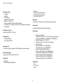
Acura Embedded Systems Inc. Industrial Computing Solutions Fan-less Computer PowerBrick AQ6 User Manual Acura Embedded Systems Inc. Published Sept 2014 www.acuraembedded.com Content Contents Chapter 1: Product Introduction Overview ............................................................................... 1 Key Features .......................................................................... 1 Hardware Specifications ........................................................... 1 Knowing PowerBrick AQ6 ......................................................... 3 Front Panel ......................................................................... 3 Rear Panel.......................................................................... 3 Mechanical Dimensions ............................................................ 4 Chapter 2: Jumpers and Connectors Connector Pin Definitions .......................................................... 5 External I/O interfaces -Front Panel ........................................... 5 Remote Power On/Off Switch ................................................... 5 COM1 Port ........................................................................... 5 COM2 Port ........................................................................... 5 DC Power Input ..................................................................... 6 Chapter 3: System Setup Installing a SO-DIMMl ............................................................... 7 Installing a CFast Card .............................................................. 8 Installing a Battery .................................................................... 8 Chapter 4: BIOS Setup About BIOS Setup .................................................................... 9 When to Configure the BIOS ....................................................... 9 Default Configuration .............................................................. 10 Entering Setup ...................................................................... 10 Legends .............................................................................. 10 BIOS Setup Utility .................................................................. 11 Main ................................................................................ 11 Advanced .......................................................................... 11 Chipset ............................................................................ 18 Security ............................................................................ 20 Boot ................................................................................. 20 Save & Exit ....................................................................... 21 Chapter 1: Product Introduction Chapter 1: Product Introduction Overview Hardware Specifications CPU Support ® ▪ Onboard Intel Atom™ processor E3845 Quad Core,1.92 GHz Main Memory ▪ 1x DDR3L SO-DIMM Socket, Support DDR3L 1066/1333 4GB RAM (Optional upgrade to 8GB ) , un-buffered and non-ECC , Display Option ▪ Dual Independent Display - HDMI and DVI-D - HDMI and VGA (via DVI-I to VGA converter) I/O Interface - Front ▪ ATX power on/off switch ▪ 1x Power Status/1x HDD Access/1x Battery Low/1x Programing LEDs ▪ 1x External CFast socket ▪ 1x SIM Card holder ® ▪ 2x Intel I210IT GbE LAN Ports, support Wake on LAN, Teaming and PXE ▪ 1x DVI-I Display Output ▪ 1x USB3.0 (900mA per each) ▪ 1x USB2.0 (500mA per each) ▪ 2x DB9 for COM1 & COM2, both support RS232/422/485 with auto flow control ▪ 1x Remote Power ON/OFF Switch ▪ 1x 2-pin DC input, support +9 to 30VDC input Key Features ▪ ▪ ▪ ▪ ▪ ▪ ▪ ▪ ▪ ® Onboard Intel Atom™ processor E3845 Quad Core,1.92 GHz. Dual Independent Display from DVI-I and HDMI ® 2x Intel I120IT LAN ports support WoL, Teaming and PXE 2x USB2.0 & 1 x USB3.0 4xCOM ports (COM1 & COM2 with RS232/422/485) 1x Optional Interface for optional Wi-Fi/3.5G/Automation modules External RTC battery holder for easy replacement Support -20 ~ 70 degree C extended operating temperature Support 9-30VDC input 1 Chapter 1: Product Introduction ▪ ▪ ▪ ▪ I/O Interface - Rear ▪ ▪ ▪ ▪ ▪ ▪ ▪ 1x USB2.0 1x HDMI 1x RTC Battery 2x DB9 for COM3 & COM4 1x Mic-in & 1 x Line-out 2x Antenna Holes for optional Wi-Fi/3.5G antenna 1x Optional I/F for optional mini-PCIe Wi-Fi/3.5G/Hilscher Automation module output Windows 7 Windows Embedded Standard 7 Windows Embedded Compact 7 Linux Kernel version 3.8.0 Dimensions ▪185mm (W) x 131mm (D) x 54mm (H) without wall-mount bracket Construction ▪Aluminum and Metal Chassis with fanless design) I/O Interface - Internal ▪4x GPI and 4 GPO (5V, TTL Type) Environment • Storage Device ▪ 1x CFast (SATA2.0) ▪ 1x 2.5” SSD (SATA2.0) • • • Expansion Slot ▪1x Mini-PCIe socket for optional Wi-Fi/3.5G/Hilscher automation modules • Power Requirements ▪Power input: +9VDC to 30VDC, 6.6A to 2A • Support OS ▪ Windows 8 ▪ Windows Embedded Standard 8 Operating Temperature: Ambient with air flow: -20°C to 70°C with industrial grade device (According to IEC60068-2-1, IEC60068-2-2, IEC60068-2-14) Storage Temperature: -30°C to 85°C Relative Humidity: 10% to 95% (non-Condensing) Shock Protection: HDD: 20G, half sine, 11ms, IEC60068-27 CFast: 50G, half sine, 11ms, IEC60068-27 Vibration Protection w/HDD Condition: Random: 0.5Grms @ 5~500 Hz, IEC60068-2-64 Sinusoidal: 0.5Grms @ 5~500 Hz, IEC60068-2-6 Vibration Protection w/CFast & SSD Condition: Random: 2Grms @ 5~500 Hz, IEC60068-2-64 Sinusoidal: 2Grms @ 5~500 Hz, IEC60068-2-6 Certifications ▪ CE ▪ FCC Class A ▪ UL/cUL 2 Chapter 1: Product Introduction Knowing PowerBrick AQ6 USB 2.0 USB 2.0 port to connect the system with USB 2.0/1.1 devices. Front Panel USB 3.0 USB 3.0 port to connect the system with USB 3.0/2.0 devices. DVI-I Used to connect a digital LCD panel. Remote On/Off Switch Used to connect a remote to power on/off the system. LAN Ports Two LAN ports used to connect the system to a local area network. COM1 and COM2 Two DB9 ports used to connect RS232/422/485 compatible devices. CFast Slot Used to insert a CFast card. SIM Slot Used to insert a SIM card. 9-30V DC Input Used to plug a DC power cord. Power/HDD LEDs Indicates the power status and HDD activity of the system. GPIO/Battery LEDs Indicates the status of the battery and GPIO. Power Button Press to power-on or power-off the system. Line-out Used to connect a headphone or a speaker. Mic-in Used to connect an external microphone. COM3 and COM4 Two DB9 ports used to connect RS232/422/485 compatible devices. Battery Slot Used to hold an external battery. HDMI Used to connect a high-definition display. USB 2.0 USB 2.0 port to connect the system with USB 2.0/1.1 devices. Fieldbus USB 2.0 DVI-I LAN Ports CFast SIM Remote On/Off USB 3.0 COM1 and COM2 9-30V DC Input Power Button Power/HDD LEDs GPIO/Battery LEDs Rear Panel Mic-in COM3 and COM4 Battery HDMI USB 2.0 Line-out Fieldbus Expansion slot for add-on fieldbus modules. 3 Chapter 1: Product Introduction 185 194 54 60 206 4 94 115 131 25 60 Mechanical Dimensions Chapter 2: Connectors Chapter 2: Connectors Connector Pin Definitions External I/O Interfaces - Front Panel Remote Power On/Off Switch COM1 Port Connector type: 2-pin switch Connector type: DB-9 port, 9-pin D-Sub 1 2 1 5 6 Pin 1 2 Definition PBT_PU GND 9 RS232 5 RS485 RS422 Pin Definition Pin Definition Pin Definition 1 2 3 4 5 6 7 8 9 SP1_DCD SP1_RXD SP1_TXD SP1_DTR GND SP1_DSR SP1_RTS SP1_CTS SP1_RI 1 2 3 4 5 6 7 8 9 SP1_DATASP1_DATA+ NC NC GND NC NC NC NC 1 2 3 4 5 6 7 8 9 SP1_TXSP1_TX+ SP1_RX+ SP1_RXGND SP1_RTSSP1_RTS+ SP1_CTS+ SP1_CTS- Chapter 2: Connectors COM2 Port DC Power Input Connector type: DB-9 port, 9-pin Connector type: 2-pin 1 5 6 1 9 RS232 RS485 RS422 Pin 1 Definition SP1_DCD Pin 1 Definition SP1_DATA- Pin 1 Definition SP1_TX- 2 3 4 5 6 7 8 9 SP1_RXD SP1_TXD SP1_DTR GND SP1_DSR SP1_RTS SP1_CTS SP1_RI 2 3 4 5 6 7 8 9 SP1_DATA+ NC NC GND NC NC NC NC 2 3 4 5 6 7 8 9 SP1_TX+ SP1_RX+ SP1_RXGND SP1_RTSSP1_RTS+ SP1_CTS+ SP1_CTS- 6 2 Pin Definition 1 2 GND_FLT VIN Chapter 3: System Setup Chapter 3: System Setup Installing a SIM Card 1. Locate the SIM card holder and release the cover. 3. Close the cover and secure the holder to the original position. SIM card holder 2. Place the SIM card onto the holder. 7 Chapter 3: System Setup Installing a CFast Card 1. Locate the CFast slot at the front and remove the cover on the slot. 2. Insert the CFast card into the slot and fasten the cover. Installing a Battery 1. Locate the battery slot at the front and remove the cover on the slot. 2. Insert the battery into the slot and fasten the cover. 8 Chapter 4: BIOS Setup Chapter 4: BIOS Setup This chapter describes how to use the BIOS setup program for the PowerBrick AQ6. The BIOS screens provided in this chapter are for reference only and may change if the BIOS is updated in the future. About BIOS Setup The BIOS (Basic Input and Output System) Setup program is a menu driven utility that enables you to make changes to the system configuration and tailor your system to suit your individual work needs. It is a ROM-based configuration utility that displays the system’s configuration status and provides you with a tool to set system parameters. These parameters are stored in non-volatile battery-backed-up CMOS RAM that saves this information even when the power is turned off. When the system is turned back on, the system is configured with the values found in CMOS. With easy-to-use pull down menus, you can configure such items as: ▪ Hard drives, diskette drives, and peripherals The settings made in the setup program affect how the computer performs. It is important, therefore, first to try to understand all the setup options, and second, to make settings appropriate for the way you use the computer. When to Configure the BIOS ▪ This program should be executed under the following conditions: ▪ When changing the system configuration ▪ When a configuration error is detected by the system and you are prompted to make changes to the setup program ▪ When resetting the system clock ▪ When redefining the communication ports to prevent any conflicts ▪ When making changes to the Power Management configuration ▪ When changing the password or making other changes to the security setup Normally, CMOS setup is needed when the system hardware is not consistent with the information contained in the CMOS RAM, whenever the CMOS RAM has lost power, or the system features need to be changed. ▪ Video display type and display options ▪ Password protection from unauthorized use ▪ Power management features 9 Chapter 4: BIOS Setup Default Configuration Most of the configuration settings are either predefined according to the Load Optimal Defaults settings which are stored in the BIOS or are automatically detected and configured without requiring any actions. There are a few settings that you may need to change depending on your system configuration. Legends Key Function Moves the highlight left or right to select a menu. Entering Setup Moves the highlight up or down between sub¬menus or fields. When the system is powered on, the BIOS will enter the Power-On Self Test (POST) routines. These routines perform various diagnostic checks; if an error is encountered, the error will be reported in one of two different ways: ▪ If the error occurs before the display device is initialized, a series of beeps will be transmitted. ▪ If the error occurs after the display device is initialized, the screen will display the error message. Powering on the computer and immediately pressing <Del> allows you to enter Setup. Another way to enter Setup is to power on the computer and wait for the following message during the POST: Exits the BIOS Setup Utility. Scrolls forward through the values or options of the highlighted field. Scrolls backward through the values or options of the highlighted field. Selects a field. TO ENTER SETUP BEFORE BOOT PRESS Displays General Help. Press the key Load previous values. to enter Setup: Scroll Bar When a scroll bar appears to the right of the setup screen, it indicates that there are more available fields not shown on the screen. Use the up and down arrow keys to scroll through all the available fields. Load optimized default values. Submenu Saves and exits the Setup program. When “” appears on the left of a particular field, it indicates that a submenu which contains additional options are available for that field. To display the Press <Enter> to enter the highlighted sub-menu submenu, move the highlight to that field and press 10 Chapter 4: BIOS Setup BIOS Setup Utility System Time Once you enter the AMI BIOS Setup Utility, the Main Menu will appear on the screen. The main menu allows you to select from several setup functions The time format is <hour>, <minute>, <second>. The time is based on the 24-hour military-time clock. For example, 1 p.m. is 13:00:00. Hour displays hours from 00 to 23. Minute displays minutes from 00 to 59. Second displays seconds from 00 to 59. and one exit. Use arrow keys to select among the items and press accept or enter the submenu. to Main Advanced The Main menu is the first screen that you will see when you enter the BIOS Setup Utility. The Advanced menu allows you to configure your system for basic operation. Some entries are defaults required by the system board, while others, if enabled, will improve the performance of your system or let you set some features according to your preference. Setting incorrect field values may cause the system to malfunction. System Date The date format is <day>, <month>, <date>, <year>. Day displays a day, from Monday to Sunday. Month displays the month, from January to December. Date displays the date, from 1 to 31. Year displays the year, from 1999 to 2099. 11 Chapter 4: BIOS Setup IT8786E Super IO Configuration ACPI Settings This section is used to configure the serial ports. This section is used to configure ACPI Settings. Super IO Chip Enable Hibernation Enables or disables system ability to hibernate (OS/S4 Sleep State). This option may not be effective with some OS. Displays the Super I/O chip used on the board. ACPI Sleep State Select the highest ACPI sleep state the system will enter when the suspend button is pressed. The options are Suspend Disabled and S3 (Suspend to RAM). 12 Chapter 4: BIOS Setup Serial Port 1 Configuration Serial Port 2 Configuration This section is used to configure serial port 1. This section is used to configure serial port 2. Serial Port Serial Port Enables or disables the serial port. Enables or disables the serial port. Onboard Serial Port Mode Onboard Serial Port Mode Select this to change the serial port mode to RS232, RS422, RS485 or RS485 Auto. Select this to change the serial port mode to RS232, RS422, RS485 or RS485 Auto. 13 Chapter 4: BIOS Setup Serial Port 3 Configuration Serial Port 4 Configuration This section is used to configure serial port 3. This section is used to configure serial port 4. Serial Port Serial Port Enables or disables the serial port. Enables or disables the serial port. Onboard Serial Port Mode Onboard Serial Port Mode Select this to change the serial port mode to RS232, RS422, RS485 or RS485 Auto. Select this to change the serial port mode to RS232, RS422, RS485 or RS485 Auto. 14 Chapter 4: BIOS Setup PPM Configuration This section is used to configure the Processor Power Management (PPM) configuration. CPU Temperature Detects and displays the current CPU temperature. System Temperature Detects and displays the current system temperature. EIST Fan Speed ® Enables or disables Intel SpeedStep. Detects and displays the fan speed. VCore H/W Monitor Detects and displays the Vcore CPU voltage VCC12 This section is used to monitor hardware status such as temperature, fan speed and voltages. Detects and displays the Vcore CPU voltage. VCC5 Detects and displays 5V voltage. VCC3 Detects and displays 3.3V voltage. 15 Chapter 4: BIOS Setup Execute Disable Bit CPU Configuration This section is used to configure the CPU. When this field is set to Disabled, it will force the XD feature flag to always return to 0. XD can prevent certain classes of malicious buffer overflow attacks when combined with a supporting OS (Windows Server 2003 SP1, Windows XP SP2, SuSE Linux 9.2, RedHat Enterprise 3 Update 3). Intel® Virtualization Technology Enables or disables Intel® Virtualization technology. Socket 0 CPU Information This section displays the information of the CPU installed in Socket 0. Active Processor Cores Select the number of cores to enable in each processor package. Limit CPUID Maximum The CPUID instruction of some newer CPUs will return a value greater than 3. The default is Disabled because this problem does not exist in the Windows series operating systems. If you are using an operating system other than Windows, this problem may occur. To avoid this problem, enable this field to limit the return value to 3 or lesser than 3. IDE Configuration This section is used to configure the SATA drives. 16 Chapter 4: BIOS Setup Enables or disables hotplug support on SATA port 1 and SATA port 2. USB Configuration This section is used to configure the USB. SATA Port1 Hotplug and SATA Port2 Hotplug Enables or disables hotplug support on SATA port 1 and SATA port 2. SATA Port1 Hotplug and SATA Port2 Hotplug Serial-ATA (SATA) Enables or disables SATA device. SATA Speed Support Configures the SATA controller to Gen1 or Gen2 speed. SATA Mode Configures the SATA as IDE, AHCI or RAID mode. SATA Mode Configures the SATA as IDE, AHCI or RAID mode. IDE This option configures the Serial ATA drives as Parallel ATA physical storage device. AHCI This option configures the Serial ATA drives to use AHCI (Advanced Host Controller Interface). AHCI allows the storage driver to enable the advanced Serial ATA features which will increase storage performance. Serial-ATA Port 0 and Serial-ATA Port 1 Enables or disables SATA port 0 and SATA port 1. Legacy USB Support Enable Enables Legacy USB. Auto Disables support for Legacy when no USB devices are connected. Disable Keeps USB devices available only for EFI applications. USB3.0 Support Enables or disables USB 3.0 controller support. XHCI Hand-off and EHCI Hand-off 17 This is a workaround for OSs that does not support XHCI hand-off and EHCI Hand-off. The XHCI and EHCI ownership change should be claimed by the XHCI and EHCI driver respectively. Chapter 4: BIOS Setup Chipset This section gives you functions to configure the system based on the specific features of the chipset. The chipset manages bus speeds and access to system memory resources. High Precision Timer Enables or disables the high precision event timer. Restore AC Power Loss Power Off When power returns after an AC power failure, the system’s power is off. You must press the power button to power-on the system. Power On When power returns after an AC power failure, the system will automatically power-on. Last State When power returns after an AC power failure, the system will return to the state where you left off before power failure occurs. If the system’s power is off when AC power failure occurs, it will remain off when power returns. If the system’s power is on when AC power failure occurs, the system will power-on when power returns. South Bridge This section is used to configure the south bridge features. 18 Chapter 4: BIOS Setup PCH Azalia Configuration USB Configuration Chapter 4: BIOS Setup Enable or Disable the PCI Express Port 0 in the Chipset. PCI Express Configuration PCI Express Port 0 [Enabled] PCI Express Port 1 [Enabled] PCI Express Port 2 [Enabled] →←: Select Screen ↑↓: Select Item Enter: Select +/-: Change Opt. F1: General Help F2: Previous Values F3: Optimized Defaults F4: Save & Exit ESC: Exit Azalia USB 2.0(EHCI) Support Control detection of the Azalia device. Version Copyright (C) 2013 American Megatrends, Inc. Disabled Azalia will2.16.1242. be unconditionally disabled. Enabled Azalia will be unconditionally Enabled. Enables or disables the Enhanced Host Controller Interface (USB 2.0), one EHCI controller must always be enabled. USB RMH Mode Azalia HDMI Codec Enables or disables PCH USB rate matching hubs mode. Enables or disables internal HDMI codec for Azalia. USB EHCI Debug Enables or disables PCH EHCI debug capability. PCI Express Configuration 19 Chapter 4: BIOS Setup PCI Express Port 0 to PCI Express Port 2 Boot Enables or disables the PCI Express ports 0 to 2 on the chipset. This section is used to configure the boot features. Security Bootup NumLock State This allows you to determine the default state of the numeric keypad. By default, the system boots up with NumLock on wherein the function of the numeric keypad is the number keys. When set to Off, the function of the numeric keypad is the arrow keys. Administrator Password Select this to reconfigure the administrator’s password. User Password Select this to reconfigure the user’s password. Fast Boot When enabled, the BIOS will shorten or skip some check items during POST. This will decrease the time needed to boot the system. 20 Chapter 4: BIOS Setup Save & Exit Network Controls the execution of UEFI and legacy PXE OpROM. Video Save Changes and Reset Controls the execution of UEFI and legacy video OpROM. To save the changes and reset, select this field then press <Enter>. A dialog box will appear. Confirm by selecting Yes. Boot Option Priorities Adjust the boot sequence of the system. Boot Option #1 is the first boot device that the system will boot from, next will be #2 and so forth. Discard Changes and Reset Hard Drive BBS Priorities To exit the Setup utility without saving the changes, select this field then press <Enter>. You may be prompted to confirm again before exiting. Boot Option #1 Sets the system boot order. Restore Defaults To restore the BIOS to default settings, select this field then press <Enter>. A dialog box will appear. Confirm by selecting Yes. 21 Chapter 4: BIOS Setup With the unique set of products, Acura Embedded Systems remains committed to its goal of providing trouble-free and customer-friendly service. A special customer service unit has been set up specifically to cater to our esteemed customers' needs. Technical Support: For technical support contact your Salesperson [email protected] Mailing address: Acura Embedded Systems Inc. Unit #1, 7711-128th Street, Surrey, BC V3W 4E6, CANADA Ph: (604) 502-9666 Fax: (604) 502-9668 Toll Free 1-866-502-9666 22