1
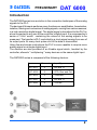
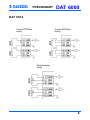
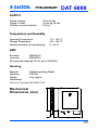
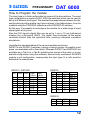
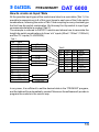
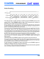
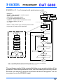
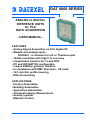
DAT 6000 SERIES
ANALOG to DIGITAL
INTERFACE UNITS
for PLC
DATA ACQUISITION
- USER MANUAL FEATURES
- Analog Signal Acquisition on PLC digital I/O
- Models and analog inputs :
DAT6021 - 4 channels for mV or Thermocouple
- 16-bits resolution with high F.S. accuracy
- Linearization function for Tc and RTD
- PC and DIP-SWITCH configurable
- 3-ways 2000Vac galvanic isolation
- In compliance with EMC directives - CE mark
- 12.5 mm thin profile housing
- DIN rail mounting
APPLICATIONS
- Factory Automation
- Building Automation
- Agricolture Automation
- Chemical Industry Measurement
- Security system
- Machine Control
PRELIMINARY
DAT 6000
Introduction
The DAT6000 series is an evolution in the connection techniques of the analog
signals to the PLC.
The devices of this serie performs many functions as: amplification, linearization,
isolation, filtering and conversion of analog signals, coming from various sensors,
in a high resolution digital signal. The digital signal is transfered to the PLC by
a bus connected to any one of the controller’s digital input. It is composed by a
series of 16-bit ‘words’ containing the values of the analog signals to be
measured. The transfer is PLC controlled by a clock signal coming from one of
its output ports. At every clock pulse a bit of the data is transmitted.
Using few and simple instructions the PLC is even capable to acquire more
analog signal on a single digital input.
The devices are also provided of an Enable signal which, handled by the
controller, allows to " multiplexing " many devices on the same digital input.
The DAT6000 series is composed of the following devices:
Device
Channels
Input Type
DAT 6011
2
mV and Tc
DAT 6012
2
RTD, Res. and Pot.
DAT 6013
2
V and mA
DAT 6021
4
mV and Tc
DAT 6023
4
V or mA
DAT6000
2
PRELIMINARY
DAT 6000
How to connect DA T6000 to PLC
D AT 60 00
P LC
+V
4.7 K
N
P
4.7 K
M
O
E N A B LE
D ATA
>560 R
C LK
GND
+V
R
D C /D C
Q
+
18..30 V dc
The serial interface of the DAT 6000 series devices is shown hereup. Input and
output signals are optoisolated among analog input and power supply. The
DATA signal circuit is powered directly with the ENABLE signal voltage. Without
the ENABLE signal, the data output is disabled. The ENABLE input
(terminal N) can be connected directly to the supply voltage, leaving available a
PLC output port; in this case the data output is always enabled. Using the
ENABLE signal, the CLK signal can be always active, because when ENABLE
signal is off, the microprocessor ignores the clock signal, stopping the data
sending; by this way, it is possible to connect many devices in multidrop
connection, using few PLC I/O ports.
The power supply of the DAT6000 is isolated from the serial interface so that
the auxiliary supply of the PLC can be used to power it.
3
PRELIMINARY
DAT 6000
Multidrop connection
The CLK input and the DATA output of the DAT6000 devices are actives only
when the ENABLE signal is on. Consequently It is possible to connect all the
DATA signals to the same PLC digital input and all the CLK signals to the same
PLC digital output. Devices can be activated one by one sending the ENABLE
signal to the selected device only.
As shown in the figure below, using n°3 DAT6000 devices it is possible to read
the value of up to 12 analog sensors using only 4 PLC digital outputs and 1 PLC
digital input. Each new device connected will use only one more PLC digital
output (ENABLE).
Changing the device type, it is possible to create many combinations of analog
inputs (i.e.: 4 Tc inputs on the first device, 4 mA inputs on the second device
and 2 Potentiometer inputs on the third device), without to change the wiring to
the PLC and the software data reading procedure.
Tc 1
N
Tc 2
Tc 3
P
D AT6021
N° 1
M
Tc 4
O
Tc 5
N
Tc 6
Tc 7
D AT6021
N° 2
P
P LC
D igital I/O
M
O
Tc 8
ENA BLE 1
ENA BLE 2
Tc 9
Tc 10
Tc 11
Tc 12
N
D AT6021
N° 3
P
M
O
ENA BLE 3
DATA
D igita l o ut
D igita l o ut
D igita l o ut
Digita l in
CLK
D igita l o ut
GN D
Ground
4
PRELIMINARY
DAT 6000
Analog Inputs connection
DAT 6011
mV
wiring
Tc
wiring
DAT 6021
mV
wiring
Tc
wiring
5
PRELIMINARY
DAT 6000
DAT 6012
2 wires RTD/Res
wiring
3 wires RTD/Res
wiring
Potentiometer
wiring
6
PRELIMINARY
DAT 6000
DAT 6013
V
wiring
mA
wiring
DAT 6023
V
wiring
mA
wiring
7
DAT 6000
PRELIMINARY
Technical Characteristics
Analog Inputs
DAT 6011, DAT 6021
mV
Input
50 mV
100 mV
500 mV
1000 mV
Min
-50 mV
-100 mV
-500 mV
-1000 mV
Thermocouple
Input
Min
Tc J
-210 °C
Tc K
-210 °C
Tc T
-210 °C
Tc E
-210 °C
Tc R
-50 °C
Tc S
-50 °C
Tc B
+400°C
Tc N
-210 °C
Channels:
Max
+50 mV
+100 mV
+500 mV
+1000 mV
Max
+1200
+1372
+400
+1000
+1767
+1767
+1825
+1300
°C
°C
°C
°C
°C
°C
°C
°C
2 ( DAT 6011 )
4 ( DAT 6021 )
Input Type:
± 50 mV to ± 1V
Calibration Accuracy:
± 0.1 F.S.
Linearity:
± 0.2 % for Tc
Lead wire resistance influence:
< 0.8 uV/Ohm
Input impedance:
> 10 MOhm
Cold Junction Compensation:
± 0.5 °C
Thermal Drift:
± 0.005 % F.S. /°C
Sampling Rate:
10 samples/sec
Bandwidth:
4 Hz
Tc: J, K, T, E, R, S, B, N
8
PRELIMINARY
DAT 6000
DAT 6012
RTD
Input
Pt100
Pt1000
Ni100
Ni1000
Min
-200°C
-200°C
-80°C
-60°C
Max
+850°C
+200°C
+180°C
+150°C
Resistance
Input
Low
High
Min
0 Ohm
0 Ohm
Max
500 Ohm
2000 Ohm
Potentiometer
Input
Min
<500 Ohm
0%
<2000 Ohm 0 %
Max
100 %
100 %
Channels:
2
Input Type:
RTD (Pt100, Pt1000, Ni100, Ni1000)
Resistance and Potentiometer (up to 2KOhm)
Calibration Accuracy:
± 0.1°C for RTD; ± 0.1 Ohm for Resistance;
RTD Linearity:
± 0.2 °C
RTD Excitation Current:
0.350 mA typ.
Lead wire resistance influence:
< 0.05 %/Ohm (50 Ohm max.) for 3 wires RTD
Thermal Drift:
± 0.005 % F.S. /°C for RTD
Sampling Rate:
10 samples/sec
Bandwidth:
4 Hz
± 0.1 % for Potentiometer;
9
PRELIMINARY
DAT 6000
DAT 6013 - DAT 6023
Voltage
Input
10 V
Min
-10 V
Max
+10 V
Current
Input
20 mA
Min
-20 mA
Max
+20 mA
Channels:
2 ( DAT 6013 )
4 ( DAT 6023 )
Input Type:
± 10V or ± 20 mA *
Calibration Accuracy:
± 0.05 %
Linearity:
± 0.1 %
Input Impedance:
> 1MOhm for V ; 47 Ohm for mA
Thermal Drift:
± 0.005 % F.S. /°C
Sampling Rate:
10 samples./sec
Bandwidth:
4 Hz
* For DAT 6023 the input type is not configurable.
It must be to defined at order (V or mA).
DIGITAL INTERFACE
Supply Voltage:
24 Vdc typical (30 Vdc max)
ON state voltage:
> 9 Vdc
Input Impedance
(ENABLE, CLK):
4.7 KOhm
Minimum Output Load
(DATA):
560 Ohm
Maximum Clock signal frequency:
< 500 Hz (with 1ms filter)
< 50 Hz (with 10ms filter)
Debounce Filter:
settable to 1ms or 10 ms
Rise Time:
<0.2 ms
10
PRELIMINARY
DAT 6000
SUPPLY
Supply Voltage:
Supply Current:
Polarity reversal protection:
18 to 30 Vdc
35 mA @ 24 Vdc
60 Vdc
Temperature and Humidity
Operating Temperature:
Storage Temperature:
Relative Humidity (not condensing):
-10 ÷ +60 °C
-40 ÷ +85 °C
0 ÷ 90 %
EMC
Emission
EN50081-2
Immunity
EN50082-2
RF Immunity tested @ 10 V/m up to 1000 Mhz
Housing
Material
Mounting
Weight
Dimensions
(W x H x T) in mm:
Selfestinguishing Plastic
DIN Rail
50 g. approx.
90 X 98 X 12.5
Mechanical
Dimensions (mm)
I
L
SW 1
G H
98
SW 4
E
F
12.5
90
11
PRELIMINARY
DAT 6000
How to Program the module
The input type is in-field configurable by means of the dip-switches. The input
type configuration is made by SW1..SW3 dip-switches which can be used to
set up to 8 different input types. The standard correspondance between the dipswitch setting and the relative input type is shown in the tables below. It can be
modified using the ‘PRO6000’ software and the PRODAT-03 interface.
By this way, it is possible to reconfigure the module for a wide range of input
signal types at any time.
Also the CLK signal’s digital filter can be set to 1 ms or 10 ms (half-period
duration) by a dip-switch (SW4). The digital filter eliminates all the signal
variations shorter than the specified time, avoiding undesired command
simulations.
Hereafter the standard tables of the various modules are shown:
DAT6012 and DAT6013 modules, having a limited number of possible input
types, are availables with a fixed table. Whereas DAT6011 and DAT6021 are
available as in Tab.A or in Tab.B, indicating the choice at the order, or in any
desired configuration using the software, as previously mentioned. DAT6023
module is not configurable; consequently the input type (V or mA) must be
defined at the order phase.
DAT6012
DAT6011 - DAT 6021
SW1 SW2 SW3
0
0
0
0
1
1
1
1
0
0
1
1
0
0
1
1
0
1
0
1
0
1
0
1
Input
Tab.A
Tc J
Tc K
Tc T
Tc E
Tc R
Tc S
Tc B
Tc N
Input
Tab.B
50 mV
100 mV
500 mV
1000 mV
---------
SW1
0
0
0
0
1
1
1
1
SW2 SW3 Input
0
0
Res. L
0
1
Res. H
1
0
Pt100
1
1
Ni100
0
0
Pt1000
0
1
Ni1000
1
0
Pot. L
1
1
Pot. H
DAT6013
SW1
x
x
SW2 SW3 Input
x
0
10 V
x
1
20 mA
12
PRELIMINARY
DAT 6000
How to create an Input Table
All the possible input types of the module are listed in a main table (Tab.1). It is
possible to associate up to 8 of this input types to each one of the 8 dip-switch
combinations, following the order of Tab.1 and compling to every choosed type
the first free dip-switch combination. By this way the ‘dip-switch to input type’
correspondence table is created (Tab.2).
The example is referred to DAT6011 module and shows how to associate the
height dip-switch combinations to three ‘mV’ inputs (50mV / 100mV / 1000mV)
and five ‘Tc’ inputs (Tc J/K/R/S/N):
Tab.1
Pos.
0
1
2
3
4
5
6
7
8
9
10
11
12
13
14
15
Input
50 mV
Tc J
Tc K
Tc T
Tc E
Tc R
Tc S
Tc B
Tc N
----100 mV
500 mV
1000 mV
50 mV
Tc J
Tc K
Tc R
Tc S
Tc N
Tab.2
SW1 SW2
0
0
0
0
0
1
0
1
1
0
1
0
1
1
1
1
SW3
0
1
0
1
0
1
0
1
Input
50 mV
Tc J
Tc K
Tc R
Tc S
Tc N
100 mV
1000 mV
100 mV
1000 mV
In any case, it is sufficient to set the desired data in the “PRO6000” program,
and the table will be automatically created. Moreover the software will provide to
program the module in the correct way.
13
PRELIMINARY
DAT 6000
Data Reading
The data transfer is made sending an enabling signal (ENABLE) and a clock
signal (CLK). If the ENABLE signal is high, a bit composing the reading is
provided on the output (DATA) at every clock pulse.
Every reading cycle is composed of 1 synchronism bit followed of a 16 bit word
for each analog input signal (channel). So that any reading is composed of 33
bits for 2-channels and 65 bits for 4-channels.
The synchronism bit indicates that the next bit is the most significant bit of the
first channel value (A15); the following remaining bits of this value will be
transmitted down to the least significant bit (A0). This bit will be followed by the
most significant bit of the second channel value (B15), down to the least significant
bit (B0). After the last bit, a new synchronism bit will be transmitted.
The value to be transmitted will be updated during the transmission of the
synchronism bit. During the reading cycle, the ENABLE signal must stay at
logic level HI.
The first bit after the ENABLE signal rise front will be a synchronism bit.
The synchronism bit level is high when the CLK signal is high and is low when
the CLK signal is low. Differently, each data bit is updated on the CLK rise front
and mantains its level until the next CLK rise front.
At any moment it is possible to send a rise front on the ENABLE signal to
restart the reading cycle (by the synchronism bit).
The ‘Debounce Filter’ eliminates all the signal variations shorter than the specified
time, avoiding undesired command simulations.
14
PRELIMINARY
DAT 6000
How to write the PLC’s instructions
The correct procedure to acquire the measures by the module can be described
as following:
Start condition:
ENABLE low and CLK low, then DATA is automatically low.
Initialization:
1 - ENABLE High
2 - Wait for Tr
Synchronism:
3 - CLK High
4 - Wait for Tr
5 - Read DATA
6 - DATA logic level must be 1 otherwise go to point 3 *
7 - CLK Low
8 - Wait for Tr
9 - Read DATA
10 - DATA logic level must be 0 otherwise go to point 3 *
Bit reading:
11 - CLK High
12 - Wait for Tr
13 - Read DATA
14 - CLK Low
15 - Wait for Tr
16 - Read DATA
17 - DATA logic level read on point 13 and on point 16 must be the same,
otherwise go to point 3 *
18 - Save the DATA logic level as bit in the reading register
Channel reading:
19 - Repeat points 11 to 18 for all the 16 bits of the measure, writing the bits
in the reading register from the most significant one down to the least
significant one
20 - Repeat points 11 to 19 for all the channels to read
21 - After the 16° bit of the last channel (2nd or 4th) return to point 3
To abort the reading without to read all the channels:
22 - Be sure the CLK is Low
23 - ENABLE Low
24 - Wait for Tr
25 - Go to point 1
* Synchronization is failed, then disregard the last reading. The data acquisition will
be delayed until the next synchronism bit will be recognized. It is advisable to abort
the reading procedure going to point 22.
NOTE: ‘Tr’ is the Debounce Filter time setting (1ms or 10 ms)
15
DAT 6000
PRELIMINARY
The following two examples, each one toghether with its flow-graph, illustrate
the procedure to be followed for writing the PLC’s instructions.
EXAMPLE n°1 : 2 or 4 channels reading
Definitions:
ENABLE, CLK and DATA = interface signals
SYNC = synchronism bit
REGISTER = data reading buffer
n = a bit of REGISTER buffer (0..15)
CHANNEL = digital channel measurement value
a = channel number (1,2,3 or 4)
x, y = bits
START
DELAY
ENABLE HIGH
DELAY
ENABLE LOW
A
DELAY = delay function (ms). The delay time must be
higher than the setting of the digital filter
NOTE 2
a=0
READ BIT
The first bit is the
most significant
n = 15
READ BIT
CLK HIGH
READ BIT
DELAY
REGISTER [n] = y
read input bit
CLK LOW
n=n-1
DELAY
NO
read next bit
n=0?
YES
y = DATA
end of channel reading
a=a+1
CHANNAEL (a) =
REGISTER
NO
read next channel
a=2?
(NOTE 1)
YES
end of channels reading
NOTE 1 : to be modified following the number of channels to be read ( write " a = 4 ? " for the 4 channels reading )
NOTE 2 : follow the (A) option to reset the device or for not reading the unused channels
The procedure is fast and with few instructions because there are not
synchronism controls. However, if the synchronism is lost (i.e. for a noise), the
reading will be wrong. To avoid that, it is advisable to use the ENABLE signal to
synchronize the procedure at the reading start.
16
PRELIMINARY
DAT 6000
EXAMPLE n°2 : 2 or 4 channels with synchronism control
START
Definitions:
ENABLE, CLK and DATA = interface signals
SYNC = synchronism bit
REGISTER = data reading buffer
n = a bit of REGISTER buffer (0..15)
CHANNEL = digital channel measurement value
a = channel number (1,2,3 or 4)
x, y = bits
DELAY
ENABLE HIGH
ENABLE LOW
DELAY
A
NOTE 2
first channel reading
a=0
DELAY = delay function (ms). The delay time must be
higher than the setting of the digital filter
READ BIT
SYNC
?
NO
YES synchronism found
READ BIT
the first bit is the
most significant
n = 15
CLK HIGH
READ BIT
DELAY
x = DATA
DATA
?
CLK LOW
NO
wrong bit received
YES
data-bit received
DELAY
REGISTER [n] = y
y = DATA
x=1
y=0
x&y
compare
read input bit
x=0
y=1
n=n-1
NO
read next bit
n=0?
YES end of channel reading
a=a+1
x=y
SYNC
DATA
ERROR
CHANNEL (a) =
REGISTER
NO
read next channel
a=2?
(NOTE 1)
YES
end of channels reading
NOTE 1 : to be modified following the number of channels to be read ( write " a = 4 ? " for the 4 channels reading )
NOTE 2 : follow the (A) option to reset the device or for not reading the unused channels
The continuous control of the received bit allow a sure synchronization of the
procedure. When the synchronism is lost, the next reading will be surely correct
because it will starts only when a synchronism bit will be recognized. It is not
necessary to use the ENABLE signal.
17
PRELIMINARY
DAT 6000
Data Format
The module acquires the analog signal value of each channel and converts it in
a digital string (bit). Each analog signal is converted in a 16 bit word which is
serially transmitted as before described.
Then, it is possible to convert the received string in the corresponding decimal
value, considering that each value is expressed in signed integer (the most
significant bit indicates the sign: 0=positive 1=negative).
The user will must insert the decimal point as illustrated in the following tables.
Input
Decimals
+/- 50 mV
+/- 100 mV
+/- 250 mV
+/- 1000 mV
+/- 20 mA
Tc J .. Tc N
3
2
2
1
3
1
Format
Input
+50.000
+100.00
+250.00
+1000.0
+20.000
+1200.0
RTD (°C)
Res (Ohm)
Pot (%)
Decimals
Format
1
1
1
+850.0
+2000.0
+100.0
Hex
Decimal
Measure
0001
2134
FFFF
F830
1
8500
-1
-2000
0.1 Ohm
85.00 mV
-0.1 mV
-200.0 °C
Examples:
Input
Binary
Ohm
100 mV
1000 mV
Tc J
0000
0010
1111
1111
0000
0001
1111
1000
0000
0011
1111
0011
0001
0100
1111
0000
18
PRELIMINARY
DAT 6000
NOTE :
19
DAT6021 4 Channel Thermocouple PLC Input
Phone: +1 225 200 7419 E-mail : [email protected] - Web Site www.datexel.com