1
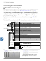
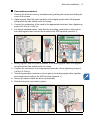
Short Form Users Manual ACS310 Table of contents Safety Mechanical installation Electrical installation Start-up and control with I/O List of related manuals DRIVE MANUALS ACS310 Short Form Users Manual ACS310 Users Manual Code (EN) 3AUA0000044200 3AUA0000044201 OPTION MANUALS MFDT-01 FlashDrop Users Manual MREL-01 Relay Output Extension Module User's Manual for ACS310/ ACS350 MUL1-R1 Installation Instructions for ACS150, ACS310, ACS350 and ACS355 MUL1-R3 Installation Instructions for ACS310, ACS350 and ACS355 MUL1-R4 Installation Instructions for ACS310 and ACS350 SREA-01 Ethernet Adapter Module Quick Start-up Guide SREA-01 Ethernet Adapter Module Users Manual Code (EN) 3AFE68591074 3AUA0000035974 3AFE68642868 2) 2) 2) 1, 2) 3AFE68643147 1, 2) 3AUA0000025916 1, 2) 3AUA0000042902 2) 3AUA0000042896 3) MAINTENANCE MANUALS Code (EN) Guide for Capacitor Reforming in ACS50, ACS55, ACS150, ACS310, 3AFE68735190 ACS350, ACS355, ACS550 and ACH550 1) Multilingual Delivered as a printed copy with the drive / optional equipment 3) Delivered in PDF format with the drive / optional equipment All manuals are available in PDF format on the Internet. See section Document library on the Internet on page 39. 2) Purpose of the manual This short form users manual provides the basic information needed for installing and commissioning the drive. For information on planning the electrical installation, operation with the control panel, program features, fieldbus, all accessible actual signals and parameters, fault tracing, maintenance, additional technical data and dimension drawings, refer to ACS310 Users Manual (3AUA0000044201 [English]). To access it on the Internet, go to www.abb.com/drives, select Document Library, enter the code in the search field and click OK. Applicability The manual is applicable to the ACS310 drive firmware version 4.00E or later. See parameter 3301 FIRMWARE in chapter Actual signals and parameters in ACS310 Users Manual (3AUA0000044201 [English]). 3AUA0000044200 Rev B EN EFFECTIVE: 2009-09-29 2009 ABB Oy. All Rights Reserved. Table of contents 3 Table of contents List of related manuals . . . . . . . . . . . . . . . . . . . . . . . . . . . . . . . . . . . . . . . . . . . . . . . . . . . . . . . 2 Purpose of the manual . . . . . . . . . . . . . . . . . . . . . . . . . . . . . . . . . . . . . . . . . . . . . . . . . . . . . . . 2 Applicability . . . . . . . . . . . . . . . . . . . . . . . . . . . . . . . . . . . . . . . . . . . . . . . . . . . . . . . . . . . . . . . . 2 1. Safety Safety in installation and maintenance . . . . . . . . . . . . . . . . . . . . . . . . . . . . . . . . . . . . . . . . . . . 5 Safe start-up and operation . . . . . . . . . . . . . . . . . . . . . . . . . . . . . . . . . . . . . . . . . . . . . . . . . . . . 6 2. Hardware description Power connections and control interfaces . . . . . . . . . . . . . . . . . . . . . . . . . . . . . . Safety ........... 7 Type designation key . . . . . . . . . . . . . . . . . . . . . . . . . . . . . . . . . . . . . . . . . . . . . . . . . . . . . . . . . 8 3. Mechanical installation Installing . . . . . . . . . . . . . . . . . . . . . . . . . . . . . . . . . . . . . . . . . . . . . . . . . . . . . . . . . . . . . . . . . . 9 4. Electrical installation Checking the compatibility with IT (ungrounded) and corner-grounded TN systems . . . . . . . Connecting the power cables . . . . . . . . . . . . . . . . . . . . . . . . . . . . . . . . . . . . . . . . . . . . . . . . . Connecting the control cables . . . . . . . . . . . . . . . . . . . . . . . . . . . . . . . . . . . . . . . . . . . . . . . . . Installation checklist . . . . . . . . . . . . . . . . . . . . . . . . . . . . . . . . . . . . . . . . . . . . . . . . . . . . . . . . . 13 14 16 18 5. Start-up and control with I/O How to start up the drive . . . . . . . . . . . . . . . . . . . . . . . . . . . . . . . . . . . . . . . . . . . . . . . . . . . . . 19 How to control the drive through the I/O interface . . . . . . . . . . . . . . . . . . . . . . . . . . . . . . . . . . 26 6. Actual signals and parameters in the short view Terms and abbreviations . . . . . . . . . . . . . . . . . . . . . . . . . . . . . . . . . . . . . . . . . . . . . . . . . . . . . Fieldbus equivalent . . . . . . . . . . . . . . . . . . . . . . . . . . . . . . . . . . . . . . . . . . . . . . . . . . . . . . . . . Default values with different macros . . . . . . . . . . . . . . . . . . . . . . . . . . . . . . . . . . . . . . . . . . . . Actual signals in the short parameter view . . . . . . . . . . . . . . . . . . . . . . . . . . . . . . . . . . . . . . . Parameters in the short parameter view . . . . . . . . . . . . . . . . . . . . . . . . . . . . . . . . . . . . . . . . . 27 27 28 29 29 7. Technical data Ratings . . . . . . . . . . . . . . . . . . . . . . . . . . . . . . . . . . . . . . . . . . . . . . . . . . . . . . . . . . . . . . . . . . 35 Power cable sizes and fuses . . . . . . . . . . . . . . . . . . . . . . . . . . . . . . . . . . . . . . . . . . . . . . . . . . 37 UL checklist . . . . . . . . . . . . . . . . . . . . . . . . . . . . . . . . . . . . . . . . . . . . . . . . . . . . . . . . . . . . . . . 38 Further information Product and service inquiries . . . . . . . . . . . . . . . . . . . . . . . . . . . . . . . . . . . . . . . . . . . . . . . . . 39 Product training . . . . . . . . . . . . . . . . . . . . . . . . . . . . . . . . . . . . . . . . . . . . . . . . . . . . . . . . . . . . 39 4 Table of contents Providing feedback on ABB Drives manuals . . . . . . . . . . . . . . . . . . . . . . . . . . . . . . . . . . . . . 39 Document library on the Internet . . . . . . . . . . . . . . . . . . . . . . . . . . . . . . . . . . . . . . . . . . . . . . 39 Safety 5 1. Safety Safety in installation and maintenance These warnings are intended for all who work on the drive, motor cable or motor. Electrical safety WARNING! Ignoring the following instructions can cause physical injury or death, or damage to the equipment. Only qualified electricians are allowed to install and maintain the drive! Never work on the drive, motor cable or motor when input power is applied. After disconnecting the input power, always wait for 5 minutes to let the intermediate circuit capacitors discharge before you start working on the drive, motor or motor cable. Always ensure by measuring with a multimeter (impedance at least 1 Mohm) that there is no voltage between the drive input phases U1, V1 and W1 and the ground. Do not work on the control cables when power is applied to the drive or to the external control circuits. Externally supplied control circuits may carry dangerous voltage even when the input power of the drive is switched off. Do not make any insulation or voltage withstand tests on the drive. Disconnect the internal EMC filter when installing the drive on an IT system (an ungrounded power system or a high-resistance-grounded [over 30 ohms] power system), otherwise the system will be connected to ground potential through the EMC filter capacitors. This may cause danger or damage the drive. See page 13. Note: When the internal EMC filter is disconnected, the drive is not EMC compatible. Disconnect the internal EMC filter when installing the drive on a corner-grounded TN system, otherwise the drive will be damaged. See page 13. Note: When the internal EMC filter is disconnected, the drive is not EMC compatible. All ELV (extra low voltage) circuits connected to the drive must be used within a zone of equipotential bonding, ie within a zone where all simultaneously accessible conductive parts are electrically connected to prevent hazardous voltages appearing between them. This is accomplished by a proper factory grounding. Note: Even when the motor is stopped, dangerous voltage is present at the power circuit terminals U1, V1, W1 and U2, V2, W2. 6 Safety General safety WARNING! Ignoring the following instructions can cause physical injury or death, or damage to the equipment. The drive is not field repairable. Never attempt to repair a malfunctioning drive; contact your local ABB representative or Authorized Service Center for replacement. Make sure that dust from drilling does not enter the drive during the installation. Electrically conductive dust inside the drive may cause damage or lead to malfunction. Ensure sufficient cooling. Safe start-up and operation These warnings are intended for all who plan the operation, start up or operate the drive. General safety WARNING! Ignoring the following instructions can cause physical injury or death, or damage to the equipment. Before adjusting the drive and putting it into service, make sure that the motor and all driven equipment are suitable for operation throughout the speed range provided by the drive. The drive can be adjusted to operate the motor at speeds above and below the speed provided by connecting the motor directly to the power line. Do not activate automatic fault reset functions if dangerous situations can occur. When activated, these functions will reset the drive and resume operation after a fault. Do not control the motor with an AC contactor or disconnecting device (disconnecting means); use instead the control panel start and stop keys and or external commands (I/O or fieldbus). The maximum allowed number of charging cycles of the DC capacitors (ie power-ups by applying power) is two per minute and the maximum total number of chargings is 15 000. Note: If an external source for start command is selected and it is ON, the drive will start immediately after an input voltage break or fault reset unless the drive is configured for 3-wire (a pulse) start/stop. When the control location is not set to local (LOC not shown on the display), the stop key on the control panel will not stop the drive. To stop the drive using the control panel, press the LOC/REM key LOC REM and then the stop key . Hardware description 7 2. Hardware description Power connections and control interfaces 8 Control panel (RJ-45) 1 SCR Screen S1 2 AI1 Analog input 1 0 10 V Reference voltage +10 V DC, max. 10 mA 3 GND mA 4 +10V V AO 7 Analog output 0 20 mA GND 8 5 AI2 Analog input 2 6 GND Aux. voltage output +24 V DC, max. 200 mA 9 +24 V 10 GND 11 DCOM 12 DI1 PROGRAMMABLE DIGITAL INPUTS 13 DI2 14 DI3 15 DI4 DI5 can also be used as a frequency input PROGRAMMABLE RELAY AND DIGITAL OUTPUTS 16 DI5 ROCOM RONC 18 RONO 19 DOSRC 20 DOOUT 21 DOGND 22 23 SHIELD Modbus RTU (EIA-485) Relay output 250 V AC / 30 V DC / 6 A Digital/frequency output, PNP transistor type 30 V DC, max. 100 mA 6 24 B J701 Output relay module MREL-01 25 A 26 GND_A FlashDrop 17 6 EMC EMC filter grounding screw VAR Varistor grounding screw PE L1 3-phase power supply, L2 200 480 V AC L3 U1 U2 V1 V2 W1 W2 M 3~ AC motor 8 Hardware description Type designation key The type designation contains information on the specifications and configuration of the drive. You find the type designation on the type designation label attached to the drive. The first digits from the left express the basic configuration, for example ACS310-03E-09A7-4. The optional selections are given after that, separated by + signs, for example +J404. The explanations of the type designation selections are described below. ACS310-03E-09A7-4+J404+... ACS310 product series 3-phase 03 = 3-phase input Configuration E = EMC filter connected, 50 Hz frequency U = EMC filter disconnected, 60 Hz frequency Output current rating In format xxAy, where xx indicates the integer part and y the fractional part, eg 09A7 means 9.7 A. For more information, see section Ratings on page 35. Input voltage range 2 = 200 240 V AC 4 = 380 480 V AC Options J404 = J400 = R700 = R701 = R702 = R707 = R708 = ACS-CP-C Basic Control Panel 1) ACS-CP-A Assistant Control Panel 1) ACS310 Users Manual in English (3AUA0000044201 [EN]) ACS310 Users Manual in German (3AUA0000048396 [DE]) ACS310 Users Manual in Italian (3AUA0000048398 [IT]) ACS310 Users Manual in French (3AUA0000048400 [FR]) ACS310 Users Manual in Spanish (3AUA0000048401 [ES]) 1) The ACS310 is compatible with panels that have the following panel revisions and panel firmware versions. To find out the revision and firmware version of your panel, see chapter Control panels, section Applicability in ACS310 Users Manual (3AUA0000044201 [English]). Panel type Type code Panel revision Panel firmware version Basic Control Panel ACS-CP-C M or later 1.13 or later Assistant Control Panel ACS-CP-A E or later 2.04 or later Assistant Control Panel (Asia) ACS-CP-D P or later 2.04 or later Note that unlike the other panels, the ACS-CP-D is ordered with a separate material code. Mechanical installation 9 3. Mechanical installation Installing The instructions in this manual cover drives with the IP20 degree of protection. To comply with NEMA 1, use the MUL1-R1, MUL1-R3 or MUL1-R4 option kit, which is delivered with multilingual installation instructions (3AFE68642868, 3AFE68643147 or 3AUA0000025916, respectively). Install the drive Install the drive with screws or on a DIN rail as appropriate. The required free space for cooling above and below the drive is 75 mm (3 in). No free space is required on the sides, so drives can be mounted immediately next to each other. Note: Make sure that dust from drilling does not enter the drive during the installation. With screws 1. Mark the hole locations using for example the mounting template cut out from the package. The locations of the holes are also shown in the drawings in chapter Dimension drawings in ACS310 Users Manual (3AUA0000044201 [English]). The number and location of the holes used depend on how the drive is installed: a) back mounting (frame sizes R0 R4): four holes b) side mounting (frame sizes R0 R2): three holes; one of the bottom holes is located in the clamping plate. 2. Fix the screws or bolts to the marked locations. 1 2 2 10 Mechanical installation 3. Position the drive onto the screws on the wall. 4. Tighten the screws in the wall securely. 3 4 On DIN rail 1. Click the drive to the rail. To detach the drive, press the release lever on top of the drive (1b). 1 1b Mechanical installation 11 Fasten clamping plates 1. Fasten the clamping plate to the plate at the bottom of the drive with the provided screws. 2. For frame sizes R0 R2, fasten the I/O clamping plate to the clamping plate with the provided screws. 1 2 12 Mechanical installation Electrical installation 13 4. Electrical installation WARNING! The work described in this chapter may only be carried out by a qualified electrician. Follow the instructions in chapter Safety on page 5. Ignoring the safety instructions can cause injury or death. Make sure that the drive is disconnected from the input power during installation. If the drive is already connected to the input power, wait for 5 minutes after disconnecting the input power. Checking the compatibility with IT (ungrounded) and corner-grounded TN systems WARNING! Disconnect the internal EMC filter when installing the drive on an IT system (an ungrounded power system or a high-resistance-grounded [over 30 ohms] power system), otherwise the system will be connected to ground potential through the EMC filter capacitors. This may cause danger or damage the drive. Disconnect the internal EMC filter when installing the drive on a corner-grounded TN system, otherwise the drive will be damaged. 1. If you have an IT (ungrounded) or corner-grounded TN system, disconnect the internal EMC filter by removing the EMC screw. For 3-phase U-type drives (with type designation ACS310-03U-), the EMC screw is already removed at the factory and replaced by a plastic one. Note: In frame size R4 the EMC screw is located to the right of terminal W2. 1 EMC VAR 14 Electrical installation Connecting the power cables Connection diagram Drive PE INPUT U1 V1 W1 OUTPUT U2 V2 W2 1) For alternatives, see chapter Planning the electrical installation, section Selecting the supply disconnecting device (disconnecting means) in ACS310 Users Manual (3AUA0000044201 [English]). 2) PE U1 V1 W1 3~ Motor L1 L2 L3 1) Ground the other end of the PE conductor at the distribution board. 2) Use a separate grounding cable if the conductivity of the cable shield is insufficient (smaller than the conductivity of the phase conductor) and there is no symmetrically constructed grounding conductor in the cable. See chapter Planning the electrical installation, section Selecting the power cables in ACS310 Users Manual (3AUA0000044201 [English]). Note: Do not use an asymmetrically constructed motor cable. If there is a symmetrically constructed grounding conductor in the motor cable in addition to the conductive shield, connect the grounding conductor to the grounding terminal at the drive and motor ends. Route the motor cable, input power cable and control cables separately. For more information, see chapter Planning the electrical installation, section Routing the cables in ACS310 Users Manual (3AUA0000044201 [English]). Grounding of the motor cable shield at the motor end For minimum radio frequency interference: ground the cable by twisting the shield as follows: flattened width > 1/5 · length or ground the cable shield 360 degrees at the leadthrough of the motor terminal box. b > 1/5 · a a b Electrical installation 15 Connection procedure 1. Fasten the grounding conductor (PE) of the input power cable under the grounding clamp. Connect the phase conductors to the U1, V1 and W1 terminals. Use a tightening torque of 0.8 N·m (7 lbf·in) for frame sizes R0 R2, 1.7 N·m (15 lbf·in) for R3, and 2.5 N·m (22 lbf·in) for R4. 2. Strip the motor cable and twist the shield to form as short a pigtail as possible. Fasten the twisted shield under the grounding clamp. Connect the phase conductors to the U2, V2 and W2 terminals. Use a tightening torque of 0.8 N·m (7 lbf·in) for frame sizes R0 R2, 1.7 N·m (15 lbf·in) for R3, and 2.5 N·m (22 lbf·in) for R4. 3. Secure the cables outside the drive mechanically. 1 1 2 2 2 16 Electrical installation Connecting the control cables Default I/O connection diagram The default connection of the control signals depends on the application macro in use, which is selected with parameter 9902 APPLIC MACRO (see page 32). The default macro is the ABB standard macro. It provides a general purpose I/O configuration with three constant speeds. Parameter values are the default values given in chapter Actual signals and parameters in ACS310 Users Manual (3AUA0000044201 [English]). For other macros, see I/O connections in chapter Application macros in the same manual, and default values on page 28 in this manual. The default I/O connections for the ABB standard macro are given in the figure below. 1 10 kohm max. 500 ohm 3) 1) X1A 1 SCR 2 AI1 3 GND 4 +10V 5 AI2 6 GND 7 AO 8 GND 9 +24V 10 GND 11 DCOM 12 DI1 13 DI2 14 DI3 15 DI4 16 DI5 X1B 17 ROCOM 18 RONC 19 RONO 20 DOSRC 21 DOOUT 22 DOGND See parameter group 12 CONSTANT SPEEDS: DI3 DI4 Operation (parameter) 0 0 Set speed through AI1 1 0 Speed 1 (1202) 0 1 Speed 2 (1203) 1 1 Speed 3 (1204) Signal cable shield (screen) Output frequency reference: 0 10 V Analog input circuit common Reference voltage: +10 V DC, max. 10 mA Not in use by default. 0 10 V Analog input circuit common Output frequency value: 0 20 mA Analog output circuit common Auxiliary voltage output: +24 V DC, max. 200 mA Auxiliary voltage output common Digital input common Stop (0) / Start (1) Forward (0) / Reverse (1) Constant speed selection 1) Constant speed selection 1) Acceleration and deceleration selection 2) Relay output 1 No fault [Fault (-1)] Digital output, max. 100 mA No fault [Fault (-1)] 2) 0 = ramp times according to parameters 2202 and 2203. 1 = ramp times according to parameters 2205 and 2206. 3) 360 degree grounding under a clamp. Tightening torque = 0.4 N·m / 3.5 lbf·in. Electrical installation 17 Connection procedure 1. Remove the terminal cover by simultaneously pushing the recess and sliding the cover off the frame. 2. Digital signals: Strip the outer insulation of the digital signal cable 360 degrees and ground the bare shield under the clamp. 3. Connect the conductors of the cable to the appropriate terminals. Use a tightening torque of 0.4 N·m (3.5 lbf·in). 4. For double-shielded cables, twist also the grounding conductors of each pair in the cable together and connect the bundle to the SCR terminal (terminal 1). 4 4 3 2 1 2 5. Analog signals: Strip the outer insulation of the analog signal cable 360 degrees and ground the bare shield under the clamp. 6. Connect the conductors to the appropriate terminals. Use a tightening torque of 0.4 N·m (3.5 lbf·in). 7. Twist the grounding conductors of each pair in the analog signal cable together and connect the bundle to the SCR terminal (terminal 1). 8. Secure all cables outside the drive mechanically. 9. Slide the terminal cover back in place. 6 4 7 7 5 5 9 18 Electrical installation Installation checklist Check the mechanical and electrical installation of the drive before start-up. Go through the checklist below together with another person. Read chapter Safety on page 5 before you work on the drive. Check MECHANICAL INSTALLATION The ambient operating conditions are allowed. (See Technical data: Losses, cooling data and noise and Ambient conditions in ACS310 Users Manual (3AUA0000044201 [English]).) The drive is fixed properly on an even vertical non-flammable wall. (See Mechanical installation on page 9 and Mechanical installation in ACS310 Users Manual (3AUA0000044201 [English]).) The cooling air will flow freely. (See Mechanical installation: Install the drive on page 9.) The motor and the driven equipment are ready for start. (See Planning the electrical installation: Checking the compatibility of the motor and drive as well as Technical data: Motor connection data in ACS310 Users Manual (3AUA0000044201 [English]).) ELECTRICAL INSTALLATION (See Electrical installation on page 13 and Planning the electrical installation in ACS310 Users Manual (3AUA0000044201 [English]).) For ungrounded and corner-grounded systems: The internal EMC filter is disconnected (EMC screw removed). The capacitors are reformed if the drive has been stored over a year. The drive is grounded properly. The input power voltage matches the drive nominal input voltage. The input power connections at U1, V1 and W1 are OK and tightened with the correct torque. Appropriate input power fuses and disconnector are installed. The motor connections at U2, V2 and W2 are OK and tightened with the correct torque. The motor cable, input power cable and control cables are routed separately. The external control (I/O) connections are OK. The input power voltage cannot be applied to the output of the drive (with a bypass connection). Terminal cover and, for NEMA 1, hood and connection box, are in place. Start-up and control with I/O 19 5. Start-up and control with I/O How to start up the drive WARNING! The start-up may only be carried out by a qualified electrician. The safety instructions given in chapter Safety on page 5 must be followed during the start-up procedure. The drive will start up automatically at power up if the external run command is on and the drive is in the remote control mode. Check that the starting of the motor does not cause any danger. De-couple the driven machine if there is a risk of damage in case of incorrect direction of rotation. Note: By default, parameter 1611 PARAMETER VIEW is set to 2 (SHORT VIEW), and you cannot see all actual signals and parameters. To be able to view them, set parameter 1611 PARAMETER VIEW to 3 (LONG VIEW). Check the installation. See the checklist in section Installation checklist on page 18. How you start up the drive depends on the control panel you have. If you have a Basic Control Panel, follow the instructions given in section How to perform a manual start-up on page 20. If you have an Assistant Control Panel, you can either run the Start-up assistant (see section How to perform a guided start-up on page 23) or perform a manual start-up (see section How to perform a manual start-up on page 20). The Start-up assistant, which is included in the Assistant Control Panel only, guides you through all essential settings to be done. In the manual start-up, the drive gives no guidance; you go through the very basic settings by following the instructions given in section How to perform a manual start-up on page 20. 20 Start-up and control with I/O How to perform a manual start-up For the manual start-up, you can use the Basic Control Panel or the Assistant Control Panel. The instructions below are valid for both control panels, but the displays shown are the Basic Control Panel displays, unless the instruction applies to the Assistant Control Panel only. Before you start, ensure that you have the motor nameplate data on hand. POWER-UP Apply input power. The Basic Control Panel powers up into the Output mode. The Assistant Control Panel asks if you want to EXIT run the Start-up assistant. If you press , the Start-up assistant is not run, and you can continue with manual start-up in a similar manner as described below for the Basic Control Panel. REM OUTPUT 00 . Hz FWD REM CHOICE Do you want to use the start-up assistant? Yes No 00:00 EXIT OK MANUAL ENTRY OF START-UP DATA (parameter group 99) If you have an Assistant Control Panel, select the REM PAR EDIT language (the Basic Control Panel does not 9901 LANGUAGE support languages). See parameter 9901 for the ENGLISH values of the available language alternatives. [0] For instructions on how to set parameters with the Assistant Control Panel, see chapter Control panels, section Assistant Control Panel in ACS310 Users Manual (3AUA0000044201 [English]). Enter the motor data from the motor nameplate: ABB Motors 3 motor V 690 Y 400 D 660 Y 380 D 415 D 440 D Cat. no 6312/C3 M2AA 200 MLA 4 IEC 200 M/L 55 No Ins.cl. F kW r/min A 30 1475 32.5 56 1475 30 1470 34 30 30 1470 59 1475 54 30 35 59 1770 Hz 50 50 50 50 50 60 3GAA 202 001 - ADA cos 0.83 0.83 0.83 0.83 0.83 0.83 6210/C3 IP 55 IA/IN t E/s 380 V supply voltage 180 IEC 34-1 CANCEL 00:00 SAVE Note: Set the motor data to exactly the same value as on the motor nameplate. For example, if the motor nominal speed is 1440 rpm on the nameplate, setting the value of parameter 9908 MOTOR NOM SPEED to 1500 rpm results in the wrong operation of the drive. Start-up and control with I/O 21 motor nominal voltage (parameter 9905) Setting of parameter 9905 is shown below as an example of parameter setting with the Basic Control Panel. You find more detailed instructions in chapter Control panels, section Basic Control Panel in ACS310 Users Manual (3AUA0000044201 [English]). REM PAR 1. To go to the Main menu, press if the bottom line shows OUTPUT; otherwise press repeatedly until you see MENU at the bottom. REM 2. Press keys press . REM / 4. Find the appropriate parameter in the group with keys / . REM REM 5. Press and hold for about two seconds until the parameter value is shown with SET under the value. REM FWD rEF -019901 9905 400 380 9905 MENU until you see PAr, and 3. Find the appropriate parameter group with keys / and press . 9905 FWD PAR FWD PAR FWD PAR FWD V PAR SET FWD 6. Change the value with keys / . The value changes faster while you keep the key pressed down. 7. Save the parameter value by pressing REM PAR SET FWD . REM PAR FWD Enter the rest of the motor data: motor nominal current (parameter 9906) Allowed range: 0.2 2.0 · I2N A REM motor nominal frequency (parameter 9907) REM motor nominal speed (parameter 9908) REM motor nominal power (parameter 9909) REM Select the application macro (parameter 9902) according to how the control cables are connected. The default value 1 (ABB STANDARD) is suitable in most cases. REM 9906 9907 9908 9909 9902 PAR FWD PAR FWD PAR FWD PAR FWD PAR FWD V 22 Start-up and control with I/O DIRECTION OF THE MOTOR ROTATION Check the direction of the motor rotation. If the drive is in remote control (REM shown on the left), switch to local control by pressing LOC REM . xxx . LOC SET FWD To go to the Main menu, press if the bottom line shows OUTPUT; otherwise press repeatedly until you see MENU at the bottom. Press keys press . / until you see rEF and Increase the frequency reference from zero to a small value with key . Press to start the motor. Check that the actual direction of the motor is the same as indicated on the display (FWD means forward and REV reverse). Press to stop the motor. forward direction reverse direction To change the direction of the motor rotation: If parameter 9914 PHASE INVERSION is not visible, first set parameter 1611 PARAMETER VIEW to 3 (LONG VIEW). LOC Invert the phases by changing the value of parameter 9914 to the opposite, ie from 0 (NO) to 1 (YES), or vice versa. LOC Verify your work by applying input power and repeating the check as described above. Set parameter 1611 back to 2 (SHORT VIEW). FINAL CHECK Check that the drive state is OK. Basic Control Panel: Check that there are no faults or alarms shown on the display. If you want to check the LEDs on the front of the drive, switch first to remote control (otherwise a fault is generated) before removing the panel and verifying that the red LED is not lit and the green LED is lit but not blinking. Assistant Control Panel: Check that there are no faults or alarms shown on the display and that the panel LED is green and does not blink. The drive is now ready for use. 1611 9914 PAR FWD PAR FWD Hz Start-up and control with I/O 23 How to perform a guided start-up To be able to perform the guided start-up, you need the Assistant Control Panel. Before you start, ensure that you have the motor nameplate data on hand. POWER-UP Apply input power. The control panel first asks if you want to use the Start-up assistant. OK Press (when Yes is highlighted) to run the Start-up assistant. EXIT Press if you do not want to run the Start-up assistant. OK Press key to highlight No and then press if you want to make the panel ask (or not ask) the question about running the Start-up assistant again the next time you switch on the power to the drive. REM CHOICE Do you want to use the start-up assistant? Yes No 00:00 OK EXIT REM CHOICE Show start-up assistant on next boot? Yes No 00:00 EXIT OK SELECTING THE LANGUAGE If you decided to run the Start-up assistant, the REM PAR EDIT display then asks you to select the language. Scroll 9901 LANGUAGE to the desired language with keys / and ENGLISH SAVE press to accept. [0] If you press EXIT , the Start-up assistant is stopped. EXIT 00:00 SAVE STARTING THE GUIDED SET-UP The Start-up assistant now guides you through the REM PAR EDIT set-up tasks, starting with the motor set-up. Set the 9905 MOTOR NOM VOLT motor data to exactly the same value as on the motor 220 V nameplate. Scroll to the desired parameter value with keys / SAVE and press to accept and continue with the Start-up assistant. EXIT 00:00 SAVE EXIT Note: At any time, if you press , the Start-up assistant is stopped and the display goes to the Output mode. The basic start-up is now completed. However, it might be useful at this stage to set the parameters required by your application and continue with the application set-up as suggested by the Start-up assistant. REM CHOICE Do you want to continue with application setup? Continue Skip 00:00 EXIT OK 24 Start-up and control with I/O Select the application macro according to which the control cables are connected. REM PAR EDIT 9902 APPLIC MACRO ABB STANDARD [1] CANCEL 00:00 Continue with the application set-up. After completing a set-up task, the Start-up assistant suggests the next one. OK Press (when Continue is highlighted) to continue with the suggested task. SAVE REM CHOICE Do you want to continue with EXT1 reference setup? Continue Skip 00:00 EXIT OK Press key to highlight Skip and then press OK to move to the following task without doing the suggested task. Press EXIT to stop the Start-up assistant. DIRECTION OF THE MOTOR ROTATION Check the direction of the motor rotation. If the drive is in remote control (REM shown on the status line), switch to local control by pressing LOC REM . If you are not in the Output mode, press repeatedly until you get there. LOC xx.xHz xx.x Hz x.x A xx.x % EXIT 00:00 DIR MENU Increase the frequency reference from zero to a small value with key . Press to start the motor. Check that the actual direction of the motor is the same as indicated on the display ( means forward and reverse). Press to stop the motor. forward direction reverse direction To change the direction of the motor rotation: If parameter 9914 PHASE INVERSION is not visible, first set parameter 1611 PARAMETER VIEW to 3 (LONG VIEW). REM PAR EDIT 1611 PARAMETER VIEW LONG VIEW [3] CANCEL 00:00 Invert the phases by changing the value of parameter 9914 to the opposite, ie from 0 (NO) to 1 (YES), or vice versa. REM Verify your work by applying input power and repeating the check as described above. [1] CANCEL 00:00 Set parameter 1611 back to 2 (SHORT VIEW). SAVE PAR EDIT 9914 PHASE INVERSION YES SAVE Start-up and control with I/O 25 FINAL CHECK After the whole set-up is completed, check that there are no faults or alarms shown on the display and the panel LED is green and does not blink. The drive is now ready for use. 26 Start-up and control with I/O How to control the drive through the I/O interface The table below instructs how to operate the drive through the digital and analog inputs when: the motor start-up is performed, and the default (standard) parameter settings are valid. Displays of the Basic Control Panel are shown as an example. PRELIMINARY SETTINGS If you need to change the direction of rotation, check that parameter 1003 DIRECTION is set to 3 (REQUEST). Ensure that the control connections are wired according to the connection diagram given for the ABB standard macro. See section Default I/O connection diagram on page 16. Ensure that the drive is in remote control. Press key LOC REM to switch between remote and local control. In remote control, the panel display shows text REM. STARTING AND CONTROLLING THE SPEED OF THE MOTOR Start by switching digital input DI1 on. Basic Control Panel: Text FWD starts flashing fast and stops after the setpoint is reached REM OUTPUT 00 . Hz 500 . Hz FWD Assistant Control Panel: The arrow starts rotating. It is dotted until the setpoint is reached. Regulate the drive output frequency (motor speed) by adjusting the voltage of analog input AI1. REM OUTPUT FWD CHANGING THE DIRECTION OF ROTATION OF THE MOTOR Reverse direction: Switch digital input DI2 on. REM OUTPUT Forward direction: Switch digital input DI2 off. REM OUTPUT STOPPING THE MOTOR Switch digital input DI1 off. The motor stops. Basic Control Panel: Text FWD starts flashing slowly. Assistant Control Panel: The arrow stops rotating. REM OUTPUT 500 . 500 . Hz REV Hz FWD 00 . FWD Hz Actual signals and parameters in the short view 27 6. Actual signals and parameters in the short view Note: When the control panel is in the short parameter view, ie when parameter 1611 PARAMETER VIEW is set to 2 (SHORT VIEW), the control panel only shows a subset of all signals and parameters. These signals and parameters are described in this chapter. To be able to view all actual signals and parameters, set parameter 1611 PARAMETER VIEW to 3 (LONG VIEW). For the description of all actual signals and parameters, refer to chapter Actual signals and parameters in ACS310 Users Manual (3AUA0000044201 [English]). Terms and abbreviations Term Definition Actual signal Signal measured or calculated by the drive. Can be monitored by the user. No user setting possible. Groups 01 04 contain actual signals. Def Parameter default value Parameter A user-adjustable operation instruction of the drive. Groups 10 99 contain parameters. Note: Parameter selections are shown on the Basic Control Panel as integer values. Eg parameter 1001 EXT1 COMMANDS selection COMM is shown as value 10 (which is equal to the fieldbus equivalent FbEq). FbEq Fieldbus equivalent: The scaling between the value and the integer used in serial communication. E Refers to types 03E- with European parametrization U Refers to types 03U- with US parametrization Fieldbus equivalent Example: If 2008 MAXIMUM FREQ (see page 31) is set from an external control system, an integer value of 1 corresponds to 0.1 Hz. All the read and sent values are limited to 16 bits (-32768 32767). 28 Actual signals and parameters in the short view Default values with different macros When application macro is changed (9902 APPLIC MACRO), the software updates the parameter values to their default values. The table below shows the parameter default values for different macros. For other parameters, the default values are the same for all macros. See the parameter list starting on page 29 in this manual and chapter Actual signals and parameters in ACS310 Users Manual (3AUA0000044201 [English]). For information on the different macros, see chapter Application macros in the same manual. Index Name/Selecti on 9902 APPLIC MACRO 1001 EXT1 COMMANDS 1002 EXT2 COMMANDS 1003 DIRECTION 1102 EXT1/EXT2 SEL 1103 REF1 SELECT 1106 REF2 SELECT 1201 CONST SPEED SEL 1304 MINIMUM AI2 1401 RELAY OUTPUT 1 1601 RUN ENABLE 1805 DO SIGNAL 2008 MAXIMUM FREQ 2201 ACC/DEC 1/2 SEL 2202 ACCELER TIME 1 2203 DECELER TIME 1 3019 COMM FAULT TIME 4001 GAIN 4002 INTEGRATION TIME 4101 GAIN 4102 INTEGRATION TIME 8116 AUX MOT STOP D 8118 AUTOCHNG INTERV 8123 PFC ENABLE ABB 3-WIRE STANDARD 1 = ABB 2 = 3STANDAR WIRE D DI1,2 DI1P,2P,3 ALTERNA TE 3 = ALTER NATE MOTOR POT 4 = MOTO R POT DI1F,2R DI1,2 HAND/AU TO 5= HAND/AU TO DI1,2 NOT SEL NOT SEL NOT SEL NOT SEL DI5,4 PID PFC SPFC CONTROL CONTROL CONTROL 6 = PID 7 = PFC 15 = SPFC CONTROL CONTROL CONTROL DI1 DI1 DI1 DI5 DI5 DI5 REQUEST REQUEST REQUEST REQUEST REQUEST FORWARD FORWARD FORWARD EXT1 EXT1 EXT1 EXT1 DI3 DI2 DI2 DI2 AI1 AI1 AI1 AI1 AI1 AI2 DI3U, 4D(NC) AI2 AI2 AI2 DI3,4 DI4,5 AI1 AI1 AI2 PID1OUT PID1OUT PID1OUT DI3,4 DI5 NOT SEL DI3 NOT SEL NOT SEL 1.0% 1.0% 1.0% 1.0% 20.0% 20.0% 20.0% FAULT(-1) FAULT(-1) FAULT(-1) FAULT(-1) FAULT(-1) FAULT(-1) PFC 20.0% PFC NOT SEL NOT SEL NOT SEL NOT SEL NOT SEL DI4 NOT SEL NOT SEL FAULT(-1) FAULT(-1) FAULT(-1) FAULT(-1) FAULT(-1) FAULT(-1) FAULT(-1) PFC 50.0 Hz 50.0 Hz 50.0 Hz 50.0 Hz 50.0 Hz 50.0 Hz 52.0 Hz 52.0 Hz DI5 NOT SEL DI5 NOT SEL NOT SEL NOT SEL NOT SEL NOT SEL 5.0 s 5.0 s 5.0 s 5.0 s 5.0 s 5.0 s 5.0 s 30.0 s 5.0 s 5.0 s 5.0 s 5.0 s 5.0 s 5.0 s 5.0 s 30.0 s 3.0 s 3.0 s 3.0 s 3.0 s 3.0 s 3.0 s 3.0 s 10.0 s 1.0 60.0 s 1.0 60.0 s 1.0 60.0 s 1.0 60.0 s 1.0 60.0 s 1.0 60.0 s 2.5 3.0 s 2.5 3.0 s 1.0 60.0 s 1.0 60.0 s 1.0 60.0 s 1.0 60.0 s 1.0 60.0 s 1.0 60.0 s 2.5 3.0 s 2.5 3.0 s 3.0 s 3.0 s 3.0 s 3.0 s 3.0 s 3.0 s 3.0 s 20.0 s NOT SEL NOT SEL NOT SEL NOT SEL NOT SEL NOT SEL NOT SEL 0.1 h NOT SEL NOT SEL NOT SEL NOT SEL NOT SEL NOT SEL ACTIVE SPFC ACTIVE Actual signals and parameters in the short view 29 Actual signals in the short parameter view Actual signals in the short parameter view No. Name/Value Description FbEq 04 FAULT HISTORY Fault history (read-only) 0401 LAST FAULT Code of the latest fault. See chapter Fault tracing in ACS310 1 = 1 Users Manual (3AUA0000044201 [English]) for the codes. 0 = Fault history is clear (on panel display = NO RECORD). Parameters in the short parameter view Parameters in the short parameter view No. Name/Value Description 11 REFERENCE SELECT Panel reference type, external control location selection and external reference sources and limits 1105 REF1 MAX Defines the maximum value for external reference REF1. Corresponds to the maximum setting of the used source signal. 0.0 500.0 Hz 12 CONSTANT SPEEDS Def/FbEq E: 50.0 Hz U: 60.0 Hz Maximum value in Hz. See the example for parameter 1104 1 = 0.1 Hz REF1 MIN in ACS310 Users Manual (3AUA0000044201 [English]). Constant speed (drive output frequency) selection and values. By default constant speed selection is made through digital inputs DI3 and DI4.1 = DI active, 0 = DI inactive. DI3 DI4 Operation 0 0 No constant speed 1 0 Speed defined by parameter 1202 CONST SPEED 1 0 1 Speed defined by parameter 1203 CONST SPEED 2 1 1 Speed defined by parameter 1204 CONST SPEED 3 For more information, see chapter Program features, section Constant speeds in ACS310 Users Manual (3AUA0000044201 [English]). 1202 CONST SPEED 1 0.0 500.0 Hz 1203 CONST SPEED 2 0.0 500.0 Hz 1204 CONST SPEED 3 0.0 500.0 Hz Defines constant drive output frequency 1. E: 5.0 Hz U: 6.0 Hz Output frequency in Hz. 1 = 0.1 Hz Defines constant drive output frequency 2. E: 10.0 Hz U: 12.0 Hz Output frequency in Hz. 1 = 0.1 Hz Defines constant drive output frequency 3. E: 15.0 Hz U: 18.0 Hz Output frequency in Hz. 1 = 0.1 Hz 30 Actual signals and parameters in the short view Parameters in the short parameter view No. Name/Value Description Def/FbEq 13 ANALOG INPUTS Analog input signal processing 1301 MINIMUM AI1 -100.0 100.0% Defines the minimum %-value that corresponds to minimum 1.0% mA/(V) signal for analog input AI1. When used as a reference, the value corresponds to the reference minimum setting. 0 20 mA = 0 100% 4 20 mA = 20 100% -10 10 mA = -50 50% Example: If AI1 is selected as the source for external reference REF1, this value corresponds to the value of parameter 1104 REF1 MIN. Note: MINIMUM AI1 value must not exceed MAXIMUM AI value. Value in percent of the full signal range. 1 = 0.1% Example: If the minimum value for analog input is 4 mA, the percent value for 0 20 mA range is: (4 mA / 20 mA) · 100% = 20% 14 RELAY OUTPUTS Status information indicated through relay output, and relay operating delays. For more information, see chapter Actual signals and parameters in ACS310 Users Manual (3AUA0000044201 [English]). 1401 RELAY OUTPUT 1 Selects a drive status indicated through relay output RO 1. The relay energizes when the status meets the setting. FAULT(-1) NOT SEL Not used 0 READY Ready to function: Run enable signal on, no fault, supply 1 voltage within acceptable range and emergency stop signal off. RUN Running: Start signal on, Run enable signal on, no active fault. 2 FAULT(-1) Inverted fault. Relay is de-energized on a fault trip. 3 PFC Start/stop motor in PFC control. See parameter group 81 PFC CONTROL in ACS310 Users Manual (3AUA0000044201 [English]). Use this option only when PFC control is used. Selection activated/deactivated when the drive is not running. 31 16 SYSTEM CONTROLS Parameter view, Run enable, parameter lock etc. 1611 PARAMETER VIEW Selects the parameter view, ie which parameters are shown SHORT on the control panel. VIEW FLASHDROP Shows the FlashDrop parameter list. Does not include the short parameter list. Parameters which are hidden by the FlashDrop device are not visible. FlashDrop parameter values are activated by setting parameter 9902 APPLIC MACRO to 31 (LOAD FD SET). 1 SHORT VIEW Shows only those signals and parameters that are listed in 2 this table and the table in section Actual signals in the short parameter view on page 29. LONG VIEW Shows all signals and parameters. See chapter Actual signals and parameters in ACS310 Users Manual (3AUA0000044201 [English]). 3 Actual signals and parameters in the short view 31 Parameters in the short parameter view No. Name/Value Description Def/FbEq 20 LIMITS Drive operation limits 2008 MAXIMUM FREQ Defines the maximum limit for the drive output frequency. E: 50.0 Hz U: 60.0 Hz Maximum frequency 1 = 0.1 Hz 0.0 500.0 Hz 21 START/STOP Start and stop modes of the motor 2102 STOP FUNCTION Selects the motor stop function. COAST COAST Stop by cutting off the motor power supply. The motor coasts to stop. 1 RAMP Stop along a ramp. See parameter group 22 ACCEL/DECEL. 2 22 ACCEL/DECEL Acceleration and deceleration times 2202 ACCELER TIME 1 Defines the acceleration time 1, ie the time required for the 5.0 s speed to change from zero to the speed defined by parameter 2008 MAXIMUM FREQ. If the speed reference increases faster than the set acceleration rate, the motor speed will follow the acceleration rate. If the speed reference increases slower than the set acceleration rate, the motor speed will follow the reference signal. If the acceleration time is set too short, the drive will automatically prolong the acceleration in order not to exceed the drive operating limits. Actual acceleration time depends on parameter 2204 RAMP SHAPE 1 setting. 0.0 1800.0 s 2203 DECELER TIME 1 0.0 1800.0 s Time 1 = 0.1 s Defines the deceleration time 1, ie the time required for the 5.0 s speed to change from the value defined by parameter 2008 MAXIMUM FREQ to zero. If the speed reference decreases slower than the set deceleration rate, the motor speed will follow the reference signal. If the reference changes faster than the set deceleration rate, the motor speed will follow the deceleration rate. If the deceleration time is set too short, the drive will automatically prolong the deceleration in order not to exceed drive operating limits. If a short deceleration time is needed for a high inertia application, note that the ACS310 cannot be equipped with a brake resistor. Actual deceleration time depends on parameter 2204 RAMP SHAPE 1 setting. Time 1 = 0.1 s 99 START-UP DATA Language selection. Definition of motor set-up data. 9901 LANGUAGE Selects the display language used on the Assistant Control ENGLISH Panel. Note: With the ACS-CP-D Assistant Control Panel, the following languages are available: English (0), Chinese (1), Korean (2) and Japanese (3). 32 Actual signals and parameters in the short view Parameters in the short parameter view No. Name/Value Description Def/FbEq ENGLISH British English 0 ENGLISH (AM) American English 1 DEUTSCH German 2 ITALIANO Italian 3 ESPAÑOL Spanish 4 PORTUGUES Portuguese 5 NEDERLANDS Dutch 6 FRANÇAIS French 7 DANSK Danish 8 SUOMI Finnish 9 SVENSKA Swedish 10 RUSSKI Russian 11 POLSKI Polish 12 TÜRKÇE Turkish 13 CZECH Czech 14 MAGYAR Hungarian 15 Selects the application macro. See chapter Application macros in ACS310 Users Manual (3AUA0000044201 [English]). ABB STANDA RD ABB STANDARD Standard macro for constant speed applications 1 3-WIRE 3-wire macro for constant speed applications 2 ALTERNATE Alternate macro for start forward and start reverse applications 3 MOTOR POT Motor potentiometer macro for digital signal speed control applications 4 HAND/AUTO Hand/Auto macro to be used when two control devices are 5 connected to the drive: Device 1 communicates through the interface defined by external control location EXT1. Device 2 communicates through the interface defined by external control location EXT2. EXT1 or EXT2 is active at a time. Switching between EXT1/2 through digital input. 9902 APPLIC MACRO PID CONTROL PID control. For applications in which the drive controls a 6 process value, eg pressure control by the drive running the pressure boost pump. Measured pressure and the pressure reference are connected to the drive. PFC CONTROL PFC (Pump and fan control) macro for pump alternation applications 7 SPFC CONTROL SPFC (Soft pump and fan control) macro for pump alternation applications where lower pressure peaks are desirable when a new auxiliary motor is started. 15 Actual signals and parameters in the short view 33 Parameters in the short parameter view No. Name/Value Description Def/FbEq LOAD FD SET FlashDrop parameter values as defined by the FlashDrop 31 file. Parameter view is selected by parameter 1611 PARAMETER VIEW. FlashDrop is an optional device for fast copying of parameters to unpowered drives. FlashDrop allows easy customization of the parameter list, eg selected parameters can be hidden. For more information, see MFDT-01 FlashDrop Users Manual (3AFE68591074 [English]). USER S1 LOAD User 1 macro loaded into use. Before loading, check that the saved parameter settings and the motor model are suitable for the application. 0 USER S1 SAVE Save User 1 macro. Stores the current parameter settings and the motor model. -1 USER S2 LOAD User 2 macro loaded into use. Before loading, check that the saved parameter settings and the motor model are suitable for the application. -2 USER S2 SAVE Save User 2 macro. Stores the current parameter settings and the motor model. -3 Defines the nominal motor voltage. Must be equal to the value on the motor rating plate. The drive cannot supply the motor with a voltage greater than the input power voltage. Note that the output voltage is not limited by the nominal motor voltage but increased linearly up to the value of the input voltage. 200 V units: 230 V 400 V E units: 400 V 400 V U units: 460 V 9905 MOTOR NOM VOLT Output voltage Input voltage 9905 9907 Output frequency WARNING! Never connect a motor to a drive which is connected to power line with voltage level higher than the rated motor voltage. 200 V units: 115 345 V 400 V E units: 200 600 V 400 V U units: 230 690 V Voltage. 1=1V Note: The stress on the motor insulations is always dependent on the drive supply voltage. This also applies to the case where the motor voltage rating is lower than the rating of the drive and the supply of the drive. 9906 MOTOR NOM CURR Defines the nominal motor current. Must be equal to the value on the motor rating plate. I2N 0.2 2.0 · I2N 9907 MOTOR NOM FREQ Current 1 = 0.1 A Defines the nominal motor frequency, ie the frequency at E: 50.0 Hz which the output voltage equals the motor nominal voltage: U: 60.0 Hz Field weakening point = Nom. frequency · Supply voltage / Motor nom. voltage 10.0 500.0 Hz Frequency 1 = 0.1 Hz 34 Actual signals and parameters in the short view Parameters in the short parameter view No. Name/Value 9908 MOTOR NOM SPEED Description Def/FbEq Defines the nominal motor speed. Must be equal to the value on the motor rating plate. Type dependent 50 18000 rpm Speed 9909 MOTOR NOM POWER 0.2 3.0 · PN kW 1 = 1 rpm Defines the nominal motor power. Must equal the value on the motor rating plate. PN Power 1 = 0.1 kW/hp Technical data 35 7. Technical data Ratings Type Input ACS3101) I1N Output I LD I2N I2max x = E/U A A A A 3-phase UN = 200...240 V (200, 208, 220, 230, 240 V) 03x-02A6-2 4.7 2.4 2.6 4.2 03x-03A9-2 6.7 3.5 3.9 6.1 03x-05A2-2 8.4 4.7 5.2 8.2 03x-07A4-2 13.0 6.7 7.4 11.7 03x-08A3-2 13.2 7.5 8.3 13.1 03x-10A8-2 15.7 9.8 10.8 17.2 03x-14A6-2 23.9 13.3 14.6 23.3 03x-19A4-2 27.3 17.6 19.4 30.8 03x-26A8-2 45 24.4 26.8 42.7 03x-34A1-2 55 31.0 34.1 54.3 03x-50A8-2 76 46.2 50.8 80.9 3-phase UN = 380...480 V (380, 400, 415, 440, 460, 480 V) 03x-01A3-4 2.4 1.2 1.3 2.1 03x-02A1-4 4.0 1.9 2.1 3.3 03x-02A6-4 4.5 2.4 2.6 4.2 03x-03A6-4 6.6 3.3 3.6 5.8 03x-04A5-4 7.6 4.1 4.5 7.2 03x-06A2-4 10.6 5.6 6.2 9.8 03x-08A0-4 12.8 7.3 8.0 12.8 03x-09A7-4 15.0 8.8 9.7 15.4 03x-13A8-4 20.7 12.5 13.8 21.9 03x-17A2-4 24.3 15.6 17.2 27.3 03x-25A4-4 34.0 23.1 25.4 40.4 03x-34A1-4 57 31 34.1 54.3 03x-41A8-4 67 38 41.8 66.5 03x-48A4-4 74 44 48.4 77.0 1) Frame size PN kW hp 0.37 0.55 0.75 1.1 1.5 2.2 3 4 5.5 7.5 11.0 0.5 0.75 1 1.5 2 3 3 5 7.5 10 15 R0 R0 R1 R1 R1 R2 R2 R2 R3 R4 R4 0.37 0.55 0.75 1.1 1.5 2.2 3 4 5.5 7.5 11 15 18.5 22.0 0.5 0.75 1 1.5 2 3 3 5 7.5 10 15 20 25 30 R0 R0 R1 R1 R1 R1 R1 R1 R3 R3 R3 R4 R4 R4 E = EMC filter connected (metal EMC filter screw installed), U = EMC filter disconnected (plastic EMC filter screw installed), US parametrization 00578903.xls D Definitions I1N I LD I2N continuous rms input current (for dimensioning cables and fuses) at ambient temperature of +40 °C continuous output current at max ambient temperature of +50 °C. 10% overloadability for one minute every ten minutes. maximum continuous output current at ambient temperature of +40 °C. No overloadability, derating 1% for every additional 1 °C up to 50 °C. 36 Technical data I2max PN R0 R4 maximum instantaneous output current. Available for two seconds every ten minutes at start-up, or as long as allowed by the drive temperature. typical motor power. The kilowatt ratings apply to most IEC 4-pole motors. The horsepower ratings apply to most NEMA 4-pole motors. ACS310 is manufactured in frame sizes R0 R4. Some instructions and other information that only concern certain frame sizes are marked with the symbol of the frame size (R0 R4) Sizing Drive sizing is based on the rated motor current and power. To achieve the rated motor power given in the table, the rated current of the drive must be higher than or equal to the rated motor current. Also the rated power of the drive must be higher than or equal to compared to the rated motor power. The power ratings are the same regardless of the supply voltage within one voltage range. Note 1: The maximum allowed motor shaft power is limited to 1.5 · PN. If the limit is exceeded, motor torque and current are automatically restricted. The function protects the input bridge of the drive against overload. Note 2: The ratings apply at ambient temperature of 40 °C (104 °F) for I2N and 50 °C (122 °F) for ILD. In multimotor systems, the output current of the drive must be equal to or greater than the calculated sum of the input currents of all motors. Derating For information on derating, see chapter Technical data, section Derating in ACS310 Users Manual (3AUA0000044201 [English]). Technical data 37 Power cable sizes and fuses Note: Larger fuses must not be used. Type ACS310- Fuses gG Size of copper conductor in cablings UL Class T Supply (600 V) (U1, V1, W1) x = E/U A A mm2 AWG 3-phase UN = 200...240 V (200, 208, 220, 230, 240 V) 03x-02A6-2 10 10 2.5 14 03x-03A9-2 10 10 2.5 14 03x-05A2-2 10 15 2.5 14 03x-07A4-2 16 15 2.5 12 03x-08A3-2 16 15 2.5 12 03x-10A8-2 16 20 2.5 12 03x-14A6-2 25 30 6.0 10 03x-19A4-2 25 35 6.0 10 03x-26A8-2 63 60 10.0 8 03x-34A1-2 80 80 16.0 6 03x-50A8-2 100 100 25.0 2 3-phase UN = 380...480 V (380, 400, 415, 440, 460, 480 V) 03x-01A3-4 10 10 2.5 14 03x-02A1-4 10 10 2.5 14 03x-02A6-4 10 10 2.5 14 03x-03A6-4 10 10 2.5 12 03x-04A5-4 16 15 2.5 12 03x-06A2-4 16 15 2.5 12 03x-08A0-4 16 20 2.5 12 03x-09A7-4 20 25 2.5 12 03x-13A8-4 25 30 6.0 10 03x-17A2-4 35 35 6.0 8 03x-25A4-4 50 50 10.0 8 03x-34A1-4 80 80 16.0 6 03x-41A8-4 100 100 25.0 4 03x-48A4-4 100 100 25.0 4 Motor (U2, V2, W2) mm2 AWG PE mm2 AWG 1.5 1.5 1.5 1.5 1.5 2.5 6 6 10 16 25 14 14 14 14 14 12 10 10 8 6 2 2.5 2.5 2.5 2.5 2.5 2.5 6.0 6.0 10.0 16.0 16.0 14 14 14 12 12 12 10 10 8 6 4 1.5 1.5 1.5 1.5 1.5 1.5 1.5 2.5 6 6 10 16 16 25 14 14 14 14 14 14 14 12 10 8 8 6 4 4 2.5 2.5 2.5 2.5 2.5 2.5 2.5 2.5 6.0 6.0 10.0 16.0 16.0 16.0 14 14 14 12 12 12 12 12 10 8 8 6 4 4 00578903.xls D 38 Technical data UL checklist The UL mark is attached to the drive to verify that it meets UL requirements. See the instructions for electrical installation in the sections in this manual or in the ACS310 Users Manual (3AUA0000044201 [English]) specified below. Input power connection See ACS310 Users Manual, chapter Technical data, section Electric power network specification. Disconnecting device (disconnecting means) See ACS310 Users Manual, chapter Planning the electrical installation, section Selecting the supply disconnecting device (disconnecting means). Ambient conditions The drives are to be used in a heated indoor controlled environment. See ACS310 Users Manual, chapter Technical data, section Ambient conditions for specific limits. Input cable fuses For installation in the United States, branch circuit protection must be provided in accordance with the National Electrical Code (NEC) and any applicable local codes. To fulfil this requirement, use the UL classified fuses given in section Power cable sizes and fuses on page 37. For installation in Canada, branch circuit protection must be provided in accordance with Canadian Electrical Code and any applicable provincial codes. To fulfil this requirement, use the UL classified fuses given in section Power cable sizes and fuses on page 37. Power cable selection See ACS310 Users Manual, chapter Planning the electrical installation, section Selecting the power cables. Power cable connections For the connection diagram and tightening torques, see section Connecting the power cables on page 14. Overload protection The drive provides overload protection in accordance with the National Electrical Code (US). Further information Product and service inquiries Address any inquiries about the product to your local ABB representative, quoting the type designation and serial number of the unit in question. A listing of ABB sales, support and service contacts can be found by navigating to www.abb.com/drives and selecting Sales, Support and Service Network. Product training For information on ABB product training, navigate to www.abb.com/drives and select Training courses. Providing feedback on ABB Drives manuals Your comments on our manuals are welcome. Go to www.abb.com/drives and select Document Library Manuals feedback form (LV AC drives). Document library on the Internet You can find manuals and other product documents in PDF format on the Internet. Go to www.abb.com/drives and select Document Library. You can browse the library or enter selection criteria, for example a document code, in the search field. ABB Oy Drives P.O. Box 184 FI-00381 HELSINKI FINLAND Telephone +358 10 22 11 Fax +358 10 22 22681 Internet www.abb.com ABB Inc. Automation Technologies Drives & Motors 16250 West Glendale Drive New Berlin, WI 53151 USA Telephone 262 785-3200 800-HELP-365 Fax 262 780-5135 ABB Beijing Drive Systems Co. Ltd. No. 1, Block D, A-10 Jiuxianqiao Beilu Chaoyang District Beijing, P.R. China, 100015 Telephone +86 10 5821 7788 Fax +86 10 5821 7618 Internet www.abb.com