1
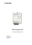
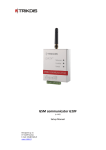
GSM module G10C Module G10C is designed for transmitting security system messages to a monitoring station through a GSM connection. Module features: Messages to the monitoring station can be transmitted in on of following modes or through GPRS connection or with SMS messages or in DTMF tones; Messages can be sent through a primary communication channel and if it fails – through a backup channel; Even if GPRS connection with two servers is lost, information can be sent with SMS messages; Sent messages correspond with Contact ID protocol codes; The module can send SMS messages to 4 user mobile phones; Input status can be controlled constantly or when control is activated; Output OUT1 status can be controlled remotely; Operating parameters and firmware version can be updated remotely; Operating parameters are set with the program G10config. Description of module operation Module G10C is connected to security control panel PGM outputs and can be set to operate in one of the two modes: a) Constant input control mode (24 h). After the security control panel has changed the state of its PGM output, module input circuit is also disturbed. The module G10C immediately sends a report about this event to the monitoring station. When the security control panel restores its PGM output status, the status of module input external circuit is also restored. The module will send a report about this event. A general wiring diagram is given in Fig. 1. b) Activated input control mode (Control panel). When this mode is selected, input MCI operates as an input status controller. While input MCI is connected with COM, disturbances in the circuits of inputs IN1...IN4 are allowed and reports about them are not created. After the circuit of input MCI is broken, the module will send a report informing that input status is controlled and disturbances in the circuits of inputs IN1...IN4 are no longer allowed. When input status is controlled by input MCI and circuits of the inputs IN1...IN4 are disturbed, the module will send reports about these disturbances/restorations. Module G10C has five inputs. When operating in 24 h mode, module MCI input is the fifth NC type input, and when operating in mode Control panel, it operates as a controller for the other four inputs. The module can send messages about the disturbances/normalisations of input IN1…IN4 and MCI external circuits to the monitoring station through a specified connection channel. If the message transmission through this channel fails, the module may send them through a backup channel. When two server IP addresses are set and the module loses connection with both of them, it can send information to the monitoring station with SMS messages. The module can periodically send signals PING for connection control. The reports can be sent with SMS messages up to four mobile phones. A user-friendly SMS message text can be assigned for every module input event. Module output OUT1 status will change when connection with the monitoring station server has been lost/restored or when the module has received an SMS message changing its output status. Module components 4 1. 2. 3. 4. 5. 6. 7. Terminal block SIM card holder USB socket GSM antenna Indicator “Network” Indicator “Data” Indicator “Power” 5 6 7 1 2 3 -3-