1
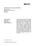
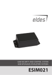
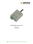
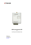
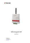
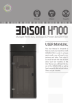
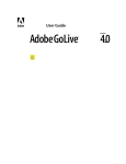
GSM module G10C (v.1.3X) Installation manual JSC UAB “TRIKDIS” Draugystės str. 17, LT-51229 Kaunas LITHUANIA E-mail: [email protected] Webpage: www.trikdis.lt Table of contents Safety requirements ................................................................................................................................................................... 2 Liability restrictions .................................................................................................................................................................... 2 GSM module G10C ..................................................................................................................................................................... 3 Description of module operation ............................................................................................................................................... 3 Module components .................................................................................................................................................................. 3 Module installation steps ........................................................................................................................................................... 4 Setting operating parameters..................................................................................................................................................... 5 Updating module firmware version ............................................................................................................................................ 9 Setting of configuration remotely............................................................................................................................................... 9 Firmware version upgrading remotely ..................................................................................................................................... 10 Remote control of the module ................................................................................................................................................. 11 Technical parameters ............................................................................................................................................................... 11 Package contents...................................................................................................................................................................... 11 ANNEX 1. Non-alarm events transmitted to ARC...................................................................................................................... 12 ANNEX2. Texts of SMS messages which are sent to mobile phone after occurring particular event........................................ 12 Safety requirements Please read this manual carefully before using the security module G10C. Security module G10C should be installed and maintained by qualified personnel, having specific knowledge regarding the functioning of GSM devices and safety requirements. Module G10C should be mounted in places with restricted access and in safe distance from any sensitive electronic equipment. The device is not resistant to mechanical effects, dampness and hazardous chemical environment. Liability restrictions When buying the Device, the Buyer agrees that the Device is a part of a security system of premises, which sends messages about security system status. The Device, when installed, does not diminish the probability of burglary, fire, intrusion or other breach of premises. UAB “TRIKDIS” is not responsible for burglary, fire or any other breach of Buyer’s and/or User’s premises and is not liable for any direct or indirect damages incurred thereof. When buying the Device, the Buyer agrees that the Device supplied by UAB “TRIKDIS” fully meets his requirements for intended use. UAB “TRIKIDIS” provides no guarantees that the Device shall function as declared if the Device is installed and used not according to its original purpose, user manual and relevant electronic and technical conditions. UAB “TRIKDIS” is in no way associated with GSM/GPRS/Internet service providers (operators), thus UAB “TRIKDIS” is in no way responsible for any defects in Device operation if they have occurred because of the loss of GSM/GPRS/Internet connection, or because of other defects in the service provider network. UAB “TRIKDIS” has no control and is not responsible for the prices and marketing of network services provided by the GSM/GPRS/Internet service providers. UAB „TRIKDIS” is not responsible if GSM/GPRS/Internet services are not provided to the Buyer and/or User of the Device or were cancelled and any direct or indirect damages were incurred thereof. UAB „TRIKDIS” is not responsible for any direct or indirect damages incurred by the Buyer and/or User of the Device due to loss of electricity. UAB „TRIKDIS” is not liable if Device firmware versions were not updated by the Buyer and/or the User on time. User manual of the Device can contain technical inaccuracies, grammatical or typographical errors. UAB “TRIKDIS” reserves the right to correct, update and/or change information in the installation manual. -2- GSM module G10C Module G10C is designed for transmitting security system messages to a monitoring station through a GSM connection. Module features: Messages to the monitoring station can be transmitted in on of following modes or through GPRS connection or with SMS messages or in DTMF tones; Messages can be sent through a primary communication channel and if it fails – through a backup channel; Even if GPRS connection with two servers is lost, information can be sent with SMS messages; Sent messages correspond with Contact ID protocol codes; The module can send SMS messages to 4 user mobile phones; Input status can be controlled constantly or when control is activated; Output OUT1 status can be controlled remotely; Operating parameters and firmware version can be updated remotely; Operating parameters are set with the program G10config. Description of module operation Module G10C is connected to security control panel PGM outputs and can be set to operate in one of the two modes: a) Constant input control mode (24 h). After the security control panel has changed the state of its PGM output, module input circuit is also disturbed. The module G10C immediately sends a report about this event to the monitoring station. When the security control panel restores its PGM output status, the status of module input external circuit is also restored. The module will send a report about this event. A general wiring diagram is given in Fig. 1. b) Activated input control mode (Control panel). When this mode is selected, input MCI operates as an input status controller. While input MCI is connected with COM, disturbances in the circuits of inputs IN1...IN4 are allowed and reports about them are not created. After the circuit of input MCI is broken, the module will send a report informing that input status is controlled and disturbances in the circuits of inputs IN1...IN4 are no longer allowed. When input status is controlled by input MCI and circuits of the inputs IN1...IN4 are disturbed, the module will send reports about these disturbances/restorations. Module G10C has five inputs. When operating in 24 h mode, module MCI input is the fifth NC type input, and when operating in mode Control panel, it operates as a controller for the other four inputs. The module can send messages about the disturbances/normalisations of input IN1…IN4 and MCI external circuits to the monitoring station through a specified connection channel. If the message transmission through this channel fails, the module may send them through a backup channel. When two server IP addresses are set and the module loses connection with both of them, it can send information to the monitoring station with SMS messages. The module can periodically send signals PING for connection control. The reports can be sent with SMS messages up to four mobile phones. A user-friendly SMS message text can be assigned for every module input event. Module output OUT1 status will change when connection with the monitoring station server has been lost/restored or when the module has received an SMS message changing its output status. Module components 4 1. 2. 3. 4. 5. 6. 7. Terminal block SIM card holder USB socket GSM antenna Indicator “Network” Indicator “Data” Indicator “Power” 5 6 7 1 2 3 -3- Terminal block description Contact +E COM IN1 IN2 IN3 IN4 OUT1 COM MCI Description +12V power supply clamp Common clamp 1st input clamp (NC type) 2nd input clamp (NC type) 3rd input clamp (NC type) 4th input clamp (NC type) Output clamp (OC type) Common clamp 5th input, programmable (NC type) Light indication LED Network presents connection with GSM network status Data presents data exchange Power presents power supply status, functioning of microcontroller and programming status Operation Green ON Yellow ON Green flashing Yellow flashing Green ON Red ON Green flashing Red flashing rapidly Red flashing Green flashing Yellow flashing Description Module is connected to a GSM network Message is being sent Connecting to GSM network Number of yellow flashes represent GSM signal strength Unsent messages present in module memory Unable to be sent messages Messages are being received from the control panel Module configuration is incorrect SIM card error Power supply is sufficient, microcontroller is functioning Power supply is not sufficient (≤11.5 V), microcontroller is functioning Programming mode Green and yellow flashing in turn Module installation steps Actions 1. Set the operating parameters for the module. Notes Follow recommendations in chapter Setting operating parameters. 2. Insert an active SIM card. Contact a GSM service provider regarding the SIM card. We do not recommend using pay as you go (prepaid) SIM cards. 3. Fasten the module to the security control panel metal casing by using either M3x6 screws or adhesive fastening tape. The location and dimensions of holes to be drilled in the casing for fastening the module and antenna: 4. Screw the GSM antenna on. 5. Connect the module to the security control panel according to the wiring diagrams given below. 6. Turn on the system power supply. 7. Check GSM signal strength according to light indication. 8. Check if the module sends messages according to its configuration See chapter Wiring diagrams. Sufficient GSM signal strength is level 5 (five yellow flashes of indicator Network). If GSM signal strength is not sufficient, use other antenna type. The message must be sent and received at the specified IP address. If messages are sent to a mobile phone, check if all SMS messages are received. -4- +AUX -AUX PGM 1 PGM 2 PGM 3 PGM 4 Security control panel / Apsaugos centralė / Охранная панель Security control panel / Apsaugos centralė / Охранная панель Wiring diagrams COM PGM 5 Relay / Relė / Реле G10C +AUX -AUX PGM 1 PGM 2 PGM 3 PGM 4 COM PGM 5 ON/OFF Relay / Relė / Реле G10C Controlled device / Valdomas prietaisas / Управляемое устройство Controlled device / Valdomas prietaisas / Управляемое устройство Fig. 1. General wiring diagram for connection to the security control panel, when constant input status control mode (24 h) is set. Fig. 2. General wiring diagram, when activatable input status control mode (Control panel) is set. Setting operating parameters Module G10C operating parameters are set with computer program G10config. Program can be found in website www.trikdis.lt. 1. Connect the module G10C with a computer using a USB cable. Note: USB drivers must be installed in the computer. If the module is connected to a computer for the first time, MS Windows OS should open a Found New Hardware Wizard window for installing USB drivers. Download the USB driver file USB_COM.inf for MS Windows OS from the website www.trikdis.lt. In the wizard window select the function Yes, this time only and press the button Next. When a new window Please choose your search and installation option” will open, press the button Browse and select the place where the file USB_COM.inf was saved. Follow the remaining wizard instructions to finish the USB driver installation. 2. Start the program G10config. 3. Select the program directory Settings. In the drop-down list Port select the port to which the module is connected. Note: specific port to which the device is connected will appear only when the device is properly connected. In the drop-down list Language select the desired program language. 4. Press the button Connect/Disconnect [F2/F8]. When the module G10C is connected to a computer, module LED Power indicator should flash green and yellow in turn. Program G10config status bar should indicate connection status Connected and display the following information about the connected module: Module type Module serial number Firmware version installed in the module 5. Press the button Read [F7]. When the window Access code opens, enter the access code (default access code is 1234) and press the button OK. If you want for the program to remember your access code check the box Remember. Then the Access code window will not open when connecting to the module for the next time. -5- Select the program directory Main and set the following parameters: Object ID Section for entering a 4-digit object identification code; SIM Card PIN code Section for entering the SIM card PIN code. Leave this field blank if PIN code request is disabled; User code Section for entering a user code. When connected using a User code, only those module parameters can be changed, which change was allowed by the administrator; Admin code Section for entering an administrator code. When connected using an Administrator code, all module parameters can be changed and also access to parameter change can be restricted for persons connecting with the User code. Operates with control panel Select in the list the operating mode of the module G10C, according to which the status of module inputs, which are connected to the security control panel PGM outputs, is controlled. If 24h is selected, input status will be constantly controlled. If Control Panel is selected, you will be able to turn the input control on or off; IN1 Function is not used; PGM If the option Remote control SMS is selected in the drop-down list, the module will change its output state after receiving an SMS message containing a control command (See chapter Remote control of the module). If the option Lost Primary channel is selected, output state will change to the opposite after losing communication through the primary channel. When the option Lost Secondary channel is selected, output state will change to the opposite after losing communication through the backup channel. If the option Lost Both channels is selected, output state will change to the opposite after losing communication through the primary and backup channels; Start sending PGM Function is not used; GPRS PING time Time interval according to which the module will send messages for GPRS connection control to the monitoring station; CSD PING time Function is not used; SMS PING time Time interval according to which the module will send SMS messages to the monitoring station to check the connection; Test time Time interval according to which the module will send Test connection control message to the monitoring station; -6- In the directory GPRS enter the parameters for connection with the monitoring station: Primary reporting The section is for setting a primary communication channel, through which the module will transmit messages to an alarm receiving centre (ARC). If GPRS is selected, IP1 address (or domain name) of ARC and a port number of the server must be specified in the corresponding boxes Server IP1 address or Domain and Port. If DATA is selected, enter telephone number of PSTN line receiver of ARC in the box Tel.1, to which module will dial messages in DTMF tones. The telephone number must be entered with international country code without the “+” (plus) sign. If SMS is selected, enter telephone number of the SMS receiver of ARC in the box Tel.1, to which module will send with SMS messages. The telephone number must be entered with international country code without the “+” (plus) sign. Backup reporting The section is for setting a backup communication channel, through which the module will transmit messages if connection through the primary communication channel has been lost. If GPRS is selected, IP2 address (or domain name) of ARC and a port number of the server must be specified in the corresponding boxes Server IP2 address or Domain and Port. If DATA is selected, enter telephone number of PSTN line receiver of ARC in the box Tel.2, to which module will dial messages in DTMF tones. The telephone number must be entered with international country code without the “+” (plus) sign. If SMS is selected, enter telephone number of the SMS receiver of ARC in the box Tel.2, to which module will send with SMS messages. The telephone number must be entered with international country code without the “+” (plus) sign. Second backup reporting tel. Telephone number of the monitoring station, to which SMS messages will be sent, when the module has lost GPRS connection with both servers. This option is allowed, when both the primary and the backup connection channels are selected as GPRS. The telephone number should be entered with international country code but without the “+” (plus) sign. Protocol Drop-down list for selecting a protocol for encrypting messages; Encryption key Section for entering a 6-digit key for encrypting messages sent to the monitoring station. The password must be same as the password entered in a server program IPcom. Return after primary Used if both the primary and backup channels are selected for connection with the monitoring station. Enter in the section the duration of time for sending messages though the backup communication channel, when connection through the primary channel has failed; reporting Used if both the primary and backup channels are selected for connection with the monitoring station. Enter in the section the number of attempts to transmit information through the primary communication channel, after which the module will connect to the backup communication channel. Backup after to Monitoring station administrator should provide the IP addresses, port and telephone numbers, encryption protocol and key with other parameters necessary for connecting with the monitoring station. -7- APN Access point name for connecting to the GSM operator’s network; User User name for connecting to the GSM network (Login); Password Password for connecting to the GSM network; DNS1, DNS2 Leave the default values in the sections. APN, user name and password should be provided by the GSM network administrator, from which you have received the SIM card. Module events Module events TIME TEST POWER IN1 IN2 IN3 IN4 IN5 Events are given in the table, about which the module will also send messages. Event code can be changed by double-clicking the cells Contact ID event code or Contact ID restore code and by entering exact values in the newly opened window. After entering the values press the button OK. Default „E“ event description Internal clock of the module is not set Periodic module Test message Power supply voltage is lower than 11,5 V Input IN1 external circuit is disturbed Input IN2 external circuit is disturbed Input IN3 external circuit is disturbed Input IN4 external circuit is disturbed Input MCI external circuit is disturbed Default „R“ event description Internal clock of the module is set Power supply voltage has restored to 12,6 V Input IN1 external circuit has restored Input IN2 external circuit has restored Input IN3 external circuit has restored Input IN4 external circuit has restored Input MCI external circuit has restored In the directory Text SMS to user enter the parameters, which are necessary to send SMS messages to users: Telephone Telephone numbers of the users should be entered in fields T1, T2, T3, T4 to which SMS messages will be sent. The telephone number should be entered with international country code but without the “+” (plus) sign; Name Choose by selecting the check boxes, about which events messages will be sent to users; Alarm/Restore SMS messages will be sent, when an input circuit is disturbed, which events are described in the table Module events with E 1xx xx xxx and R 1xx xx xxx codes (security system alarm: fire, burglary, trespass, assault and etc.); Open/Close SMS messages will be sent, when an input circuit is disturbed, which events are described in the table Module events with E 4xx xx xxx and R 4xx xx xxx codes (security system arm/disarm); Troubles SMS messages will be sent, when an input circuit is disturbed, which events are described in the table Module events with E 3xx xx xxx and R 3xx xx xxx codes (security system troubles); Tests SMS messages will be sent, when an input circuit is disturbed, which events are described in the table Module events with E 6xx xx xxx code (security system Test messages); SMS encoding Choose in the list the preferred encoding for the text in SMS messages; Send SMS When All is chosen, SMS messages will be sent to users about all module external circuit events. When Described Only is chosen, SMS messages will be sent to users only about those external circuit events, which are described; Object ID Enter the object name. It will be included in the message sent to user; -8- Users Function is not used; Zones Entries in the table are associated with PGM output events controlled by the security control panel. When a connected module input circuit is alarmed/restored, its description entered in the table will be included in the SMS message; Partitions (1) If the security system is divided into several individually protected areas and (2) if control panel PGM output events shall mark events in these areas, then entries in the table are associated with these events. If a connected module input circuit is alarmed/restored, the name of the partition entered in the table will be included in the SMS message; 6. Press the button Save [F6] and values entered in the program G10config windows will be uploaded to the module G10C. 7. Press the button Disconnect [F8] and unplug the USB cable from the USB socket. Save [F5] By pressing this button values entered to the program G10config can be saved in the computer. A new file with extension .gst will be created. It can be used later as a template for configuring other modules. Restore [F11] Button for restoring default (factory) operating parameters of the module G10C. Press the button Yes when request window opens. Updating module firmware version When the manufacturer adds new features to the module G10C, firmware of the previously bought module can be updated: 1. Download the latest G10C_vx.xxx.prg update file from the website www.trikdis.lt. 2. Connect the module G10C to a computer and start the program G10config. Open directory Firmware update and select the file G10C_vx.xxx.prg saved in the computer. 3. Press the button Start [F9]. Wait until file uploading bar Progress is full, and then press the button Disconnect [F8]. Unplug the USB cable. 4. Plug the USB cable back in. Firmware update process may take 60-90 seconds. Wait until indicator Data will stop flashing green and press the buttons Connect [F2] and Read [F7]. The new version of the module firmware will be displayed in G10config program status bar. Setting of configuration remotely In order to set module G10C operating parameters remotely a SMS message with the particular syntax must be sent by GSM number of SIM card put in the module G10C. When the module G10C receives this SMS message it opens GPRS communication session with software IPcom. If during the previous setting module operating parameters were being entered GSM number of authorised person in the list G10config / Settings / Wireless programming phones, the module G10C will open GPRS communication session, if it receives SMS message with particular syntax from authorized person‘s phone. SMS message text structure (word space means space between SMS text symbols): CONNECTspace1234spaceSERVER=100.100.100.100spacePORT=1000spaceAPN=providerspaceUSR=namespacePSW=pswspaceENCR=enc Note: entering values use capital letters! -9- Description of syntax: CONNECT 9874 SERVER=value PORT=value APN=value USR=value PSW=value ENCR=value Enter the word “CONNECT” means starting command; Enter your 4-digit access code to module parameter configuration (default is 1234); Enter the word “SERVER=” + enter IP address of the IP receiver, from which module operating parameters will be configured; Enter the word “PORT=” + enter port of the receiver, from which module operating parameters will be configured; Enter the word “APN=” + enter the GPRS access point name of network where SIM card is operating. If GSM service provider doesn’t require any value must be entered, just leave ...spaceAPN=space... in SMS; Enter the word USR= + enter the User name of GPRS access point name of network where SIM card is operating. If GSM service provider doesn’t require any value must be entered, just leave ...spaceUSR=space... in SMS; Enter the word “PSW=” + enter the Password of GPRS access point name of network where SIM card is operating. If GSM service provider doesn’t require any value must be entered, just leave ...spacePSW=space... in SMS; Enter the word “ENCR=” + enter the 6-digit messages decrypting key which is set in IP receiver (default is 123456). Order of actions after the message is sent: 1. Open the window of software IPcom and select the object ID, which operating parameters of transmitting module should be changed. To select, right click on the ID number. 2. Open the configuration program G10config. Left click on the icon G10config has been appeared beside the selected ID number. 3. Click on the button Connect in the opened program G10config tool bar. GPRS connection status “Connected” must be indicated in the program’s status bar. Click the button Read [F7] on, old configuration to be displayed. 4. Further actions are identical as when the module is connected to a computer with a USB cable. Just set the desirable values of module operating parameters in the opened program G10config windows. 5. After entering desirable values click the button Write [F6] on, the values to be set in the module G10. Just close the program G10config and GPRS communication session closes too. Firmware version upgrading remotely Connect the module G10C with the program G10config remotely (See previous chapter how to connect remotely). 1. Open the program G10config (See previous chapter how to open the configuration program) 2. Press the button Connect. 3. To read the parameters set in the module press the button Read. 4. Open the window Firmware and with clicking on the button Browse select the latest version of the firmware file. Press the button Start. 5. Wait until the firmware will be written into the module processor memory. This may take 1-3 minutes, after which the module will reconnect to the program G10config. 6. Set the module operating parameters in the same way as described while connected via USB port. - 10 - Remote control of the module In order to change the status of output OUT1, send an SMS message to module SIM card number. Examples of SMS messages are given in the table. Notes: If the table Wireless programming phones is empty, the module will change its output status after receiving an SMS message from any phone. If telephone numbers are entered into this table, module output status can be changed only from these phones; Output status can be changed when the operating mode for output OUT1 is set to Remote PGM control SMS; SMS message should be written in capital letters only! SMS message text OUTPUT ˽ 1234 ˽ ON OUTPUT ˽ 1234 ˽ OFF OUTPUT ˽ 1234 ˽ PULSE=005 RESET ˽ 1234 Description Output status is changed to ON Output status is changed to OFF Output status is changed to ON for a time period entered in seconds Module is restarted Note Instead of numbers 1234 enter the Administrator or a User code. Symbol „˽“ indicates a space in SMS message text. Technical parameters Power supply voltage Used current GSM modem frequency Memory Inputs Output Setting configuration Operating environment Dimensions DC 12,6 ± 3 V 60–100 mA (stand-by) Up to 250 mA (transmitting) 850 / 900 / 1800 MHz Up to 60 messages 4+1, NC type 1 OC type, commutating a direct 1 A current with 30 V voltage Through the USB port From -10 °C to 50 °C, with relative air humidity 80% with +20 °C 65 x 79 x 25 mm Package contents Module G10C Adhesive fastening tape (10 cm) 1 pc. 1 pc. Note: GSM antennas of desired type are collected by the additional request. - 11 - ANNEX 1. Non-alarm events transmitted to ARC Event description Event code Activated Restored E 602 - E 700 R 700 E 702 R 702 PING signal through SMS channel E 750 - Connection by SMS channel: lost / restored E751 R 751 PING signal through GPRS channel E 760 - Connection by GPRS channel: lost / restored E 761 R 761 PING signal dialled in DTMF tones E 770 - E 144 99 999 R 144 99 999 Device TEST message Time is specified yes / no Connection with the security panel lost / restored Notes Not specified st 1 NC input Activated / restored Input mode ANNEX2. Texts of SMS messages which are sent to mobile phone after occurring particular event Control panel CID code E/R 100 E/R 110, 115 E/R 120 Sent as E 100 R 100 E 110 R 100 E 120 R 120 E 121 E/R 130, 144 E/R 301 E/R 302, 309 E/R 321 E/R 351 E/R 400, 401, 406, 451 E/R 408 E 602 E 130 R130 E 301 R 301 E 302 R 302 E 321 R 321 E 351 R 351 E 401 R 401 E 408 R 408 E 602 Text Existing MEDICAL PANIC ALARM In CID standard Medical Alarm FIRE PANIC ALARM Fire Alarm PANIC ALARM Panic Alarm DURESS ALARM ALARM Alarm restore AC Power failure on control panel AC Power failure restored on control panel Battery Power failure on control panel Battery Power restored failure on control panel Bell trouble on control panel Bell trouble restore on control panel Phone Line trouble on control panel Phone Line trouble restored on control panel OPEN by CLOSE by Quick DISARM Quick ARM Periodic Test Duress Alarm Burglary Alarm Burglary Alarm restore AC Loss AC Loss restore Low System battery Low system Battery restore Bell 1 Bell 1 restore Telco 1 fault Telco 1 fault restore Open by user Close by user Quick DISARM Quick ARM Periodic test report - 12 -