1
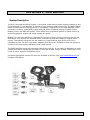
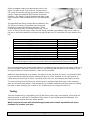
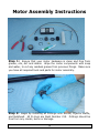
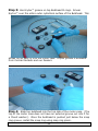
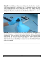
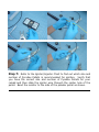
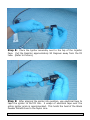
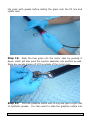
Universal Launch System Remote Tanking and Launching System for Sport Rocketry User Guide This is the instruction manual for all three modules of the Universal Launch System (ULS). Module 1, the Base Unit, is capable of firing conventional solid fuel rocket motors. Module 2, the Valve Manifold, attaches to a nitrous oxide (N2O) supply tank (not supplied) and allows the filling and venting of floating-injector hybrid motors. Module 3, the GOX/HV Ignition Module, connects to the Base Unit module and a gaseous oxygen (GOX) supply tank, and allows the firing of non-pyrotechnic hybrid motors. Pratt Hobbies, 2513 Iron Forge Road, Herndon, VA 20171 www.pratthobbies.com Table of Contents ULS Module 1: Base Module .......................................................................3 System Description ........................................................................................... 3 The Hand Controller .......................................................................................... 4 Setting Up the System on the Field ................................................................... 5 Launch Procedure ............................................................................................. 6 Care and Maintenance....................................................................................... 6 ULS Module 2: Valve Manifold ....................................................................7 System Description ........................................................................................... 7 Setting Up the System ...................................................................................... 8 Adapters ........................................................................................................... 8 Testing.............................................................................................................. 9 Launch Procedure ........................................................................................... 10 Misfire Procedure............................................................................................ 10 Care and Maintenance..................................................................................... 10 ULS Module 3: GOX/HV IGNITION MODULE .............................................11 System Description ......................................................................................... 11 Required to Use: ............................................................................................. 11 Setting Up the GOX/HV IGNITION module ..................................................... 12 The GOX Regulator ......................................................................................... 12 The Control Module ......................................................................................... 12 Testing the System ......................................................................................... 13 Setting Up for Launch ..................................................................................... 13 Care and Maintenance..................................................................................... 13 Notes .......................................................................................................14 Disclaimer....................................................................................................... 14 More information ............................................................................................ 14 Getting Started with Hybrid Motors ................................................................ 14 Web links ........................................................................................................ 16 Hybrid Motor Instructions........................................................................17 2 ULS Module 1: Base Module System Description The ULS Base Module is a rocket ignition system powered by one or two external 12 volt batteies. The Base Module is designed to put more power into an igniter than other launch systems. The battery is close to the launch pad, and only has eight feet of heavy gauge wire between it and the igniter. The control relays are powered by a 9v battery in the Hand Controller. Effectively all of the high-current 12 volt battery’s power goes straight to the igniter. The continuity sensing circuit is transistorized, and will not set off sensitive igniters like flashbulbs or electric matches. Pressing the Continuity Test button lights an ultrabright LED if the igniter circuit is complete. A buzzer sounds when the unit is set to Pad Armed. 12 volt operation is sufficient for most Black Powder and APCP (composite) propellant solid rocket motors, as well as most common hybrid motors. 24 volt operation is required for the older igniters supplied with Contrail Rockets hybrid motors. 24 volt operation is also very useful for cluster ignition or custom-made high-current igniters. Control circuitry built into the ULS will allow the filling and venting of hybrid rocket motors when combined with other modules. When you are ready for hybrids, you can add the Valve Manifold Module and a N2O supply tank to fire “floating injector” motors, like RATT Works, Propulsion Polymers, Sky Ripper, Contrail Rockets and West Coast Hybrids. Connecting the GOX/HV Ignition Module gives you the capability of connecting to a HyperTEK non-pyrotechnic motor system. Optional 500 foot and 1000 foot cables allow you to meet the distance requirements for larger motors as listed in the NAR and Tripoli Safety Codes. 3 The ULS-M1 can also be supplied with a built-in battery meter that shows the voltage available from the battery or batteries when the Test button is pressed. System Components ULS base unit housed in plastic casing with handle Battery Cables (2) 100 foot cable (standard) Hand controller Bulb tester Igniter Cable Alligator clips (two sets) Jumper plug Safety Interlock Plug NOTE: There is a compartment in the lid of the ULS-M1 case. The Safety Interlock Plug, Alligator Clips and Bulb Tester are generally shipped in this compartment. The Hand Controller The ULS Hand Controller contains a 9v battery to activate the relays in the ULS Base Module. A good battery should last through a typical flying season. We recommend Duracell Ultra batteries. To install the battery, remove the four screws on the back plate of the Hand Controller. Insert a fresh 9 volt battery into the clip and attach the battery connector. Reattach the back plate with the four screws. The Hand Controller also includes a Safety Interlock Plug, This plug provides a removable interlock that prevents activation of the ignition circuit unless it is inserted. The Safety Interlock Plug is supplied on a convenient lanyard that can be worn around your neck. The lanyard has a quick-release latch to allow you to remove the Safety Interlock Plug for insertion into the Hand Controller. It is your responsibility to maintain control of the Safety Interlock Plug at all times, to prevent accidental ignition. 4 Setting Up the System on the Field Open up the ULS case and put it down close to the launch pad. Place it in a position where it is in no danger from the motor's flame at liftoff. The case must be no more than six feet from the rocket igniter, to allow some slack in the cable that attaches to the igniter. For 12 volt operation: Plug one of the two Battery Cables into the Battery A jack on the ULS faceplate. Connect the clips to your 12 volt supply battery. Be certain that polarity is correct: Red to Positive and Black to Negative! Make sure that the clips cannot touch each other or short against any metal object. Insert the Jumper Plug into the Battery B jack on the ULS faceplate. (The Jumper Plug is usually kept in this position by default.) For 24 volt operation: Plug one of the two Battery Cables into the Battery A jack on the ULS faceplate. Connect the clips to one of your 12 volt supply batteries. Be certain that polarity is correct: Red to Positive and Black to Negative! Make sure that the clips cannot touch each other or short against any metal object. Plug the other Battery Cable into the Battery B jack on the ULS faceplate. Check the polarity on both batteries to be certain that you have Red to Positive and Black to Negative. If polarity is backward on either battery, the two batteries will attack each other when the Ignition command is given, and the wrong part of the system will ignite. This is not covered under warranty. Also, do not connect both sets of clamps to one battery. Uncoil the 100-foot launch controller wire and insert one end into the jack marked Controller on the ULS faceplate. Connect the Hand Controller to the other end. To be certain that you have it connected properly, press the Fill and Drain rocker switch momentarily on the hand controller and listen for the relays clicking inside the ULS when you do. The Ignition button is deactivated unless the Safety Interlock is in place, so you should not hear a relay click if you press the Ignition button. Uncoil the 8-foot pad cable. This cable has a two-prong connector on one end and banana plugs on the other. Plug the two-prong connector into the socket on the Base Module marked Ignition. Slide two alligator clips on the banana plugs at the other end. The alligator clips are kept in the small parts container on the Base Module lid; two extra clips are included. We recommend wrapping the alligator clips and the banana plugs with electrical tape after the clips are connected to your igniter. This will prevent them from shorting against each other, and help keep them from being pulled out and lost by a high power rocket motor that lifts off before the igniter wire burns away. Testing A 12V Bulb Tester is included with the ULS. This takes the place of an igniter in tests, and also allows you to test the solenoid control circuits. After setting up the system (see above), connect the Bulb Tester to the igniter clips and go through the launch procedure. The bulb will light when you press the Fire button. You can use the pad cable and Bulb Tester to test the Fill and Dump outputs by plugging the cable into either the Fill or Dump socket and moving the rocker switch on the Hand Controller. 5 Launch Procedure Follow the checklist printed on the ULS Base Module faceplate. Make sure the Base Module is switched to PAD SAFE. Connect the alligator clips to your igniter. Make certain that the clips do not touch each other or any metal parts. We recommend wrapping each clip with electrical tape. Press the CONTINUITY TEST button. The LED will illuminate if the circuit through the igniter is complete. (Note: The Continuity Test circuit only functions when the switch is in the PAD SAFE position.) Move the switch on the ULS faceplate to the PAD ARMED position. The warning buzzer will sound. Go to your launch position, at least 50 feet away from the pad. Clear the area, check the sky for aircraft, and alert all spectators. Insert the Safety Interlock Plug in the Hand Controller. Begin your countdown and firing sequence. After launch, immediately remove the Safety Interlock Plug from the Hand Controller. Return to the launch pad and move the Pad Safe/Armed switch to the PAD SAFE position. The warning buzzer operates all the time that the switch is in the PAD ARMED position, to remind you to safe the system after launch. Misfire Procedure If the rocket motor does not ignite, remove the Safety Interlock Plug and wait at least 60 seconds before approaching the launch pad. Move the Safe/Armed switch on the ULS faceplate to the PAD SAFE position as soon as you return to the pad. Care and Maintenance Make sure the Pad Safe/Pad Armed switch is in the PAD SAFE position unless you are ready to launch. Wrap the cables neatly and use the reusable tie wraps to secure the bundles. Store all the parts inside the Base Module case. The ULS system requires no maintenance other than light cleaning. The alligator clips are easily replaceable. You can order more clips from us when you need them, or get them at an electronics store. 6 ULS Module 2: Valve Manifold System Description The ULS (Universal Launching System) is a modular rocket launch control system powered by one or two external 12-volt batteries. It consists of yjtrr Modules. Module One is the ULS Base Module, which contains control circuitry and the 12 volt battery. Module Two is the Valve Manifold, which connects to a nitrous oxide (N2O) supply tank and allows filling and venting of hybrid motors. Module Three is the GOX/HV Ignition, which allows non-pyrotechnic ignition of hybrid motors by controlling gaseous oxygen and a high-voltage arc igniter. Module Two, the Valve Manifold, is designed to connect to control circuitry built into the ULS-M1 Base Block. This controls two solenoid valves, to allow the filling and venting of hybrid rocket motors. The solenoid valves we use are made to our specifications, and will not burn out in extended use like "hot rod" type valves. Adapters and fittings are included to allow the system to connect to all commercially available hybrid rocket motors. The Valve Manifold comes with connectors that fit the ULS-M1. It can easily be adapted to a multichannel club launch system that provides 12 volts and at least 2 amps. Simply connect one circuit to the fill valve, and one to the dump valve. A pressure gauge and oversize fill valve are available as options. See www.pratthobbies.com for complete information. 7 Setting Up the System Nitrous oxide (N2O) tanks are fitted with one of three different types of valves. Anaesthetic or medical-grade N2O tanks are not used with hybrid rocket motor systems; these valves have a limited flow rate to prevent possible injury, and cannot supply adequate flow to fill a hybrid motor. Medical grade tanks can be recognized from their chrome-plated valves. The two valve types that can be used with rocket motors are designated CGA-326 and CGA-660. These numbers are usually stamped into the valve. The ULS Valve Manifold comes equipped with a nipple and nut to fit a CGA326 tank valve. CGA-660 fittings are available as an option. Note: Industrial-grade and racing-grade N2O include an additive that produces a strong, unpleasant smell, usually butyl mercaptan or sulfur dioxide. This is done to make it impossible to use the “denatured” N2O as a recreational drug, allowing hobbyists to buy it without restriction. It also functions as a way of detecting leaks, the same as the “leak check” compounds usually added to natural gas. Connect the ULS Valve Manifold to your supply tank with a suitable wrench. The nut does not have to be tightened too hard. Position the Valve Manifold so that the outlet of the Dump valve is pointing down. If you need to dump the N2O in a motor on the pad, it will vent through this outlet at a high rate of speed. Just like a rocket, this will cause an opposite force, and it can knock your N2O tank over, possibly damaging the valve assembly. Open the tank valve and listen for leaks. If you hear hissing, close the tank valve and wait for the hissing to stop, then tighten the tank nut. If hissing continues, examine other parts of the manifold that may need tightening. Note: Liquid N2O has a temperature of minus 65 degrees and can cause frostbite if it touches your skin. Be very careful not to touch any ice formed by leaking N2O, or any metal parts that have been chilled by leaking N2O. Position the nitrous oxide (N2O) supply tank so that the pressure tubing from the motor can easily reach the fitting on the valves. Plug the Fill valve (the one closest to the tank) into the connectors marked FILL on the Base Module faceplate. Plug the dump valve (the one on the end of the T fitting that opens to the atmosphere) into the connectors marked Dump on the Base Module faceplate. Adapters The ULS Valve Manifold includes a set of adapters intended to connect to all commercially available hybrid rocket motors. These adapters screw into the outlet side of the Tee Fitting on the Manifold. 8 Select an adapter that is the appropriate size for the motor you plan to use. The Sure-Lok connectors are PTC (push-to-connect) fittings for various sizes of nylon tubing. These are used with RATT Works, Propulsion Polymers, Sky Ripper, Contrail Rockets and West Coast Hybrids motors. See the table below for the appropriate size. The tapered brass fitting (shown above installed in the Tee Fitting) connects to a stainless steel hose that connects to a HyperTEK fill stem assembly. 75mm Contrail Rockets motors fill through two hoses. To set up for a 75mm Contrail motor, screw the tee fitting provided in the adapter bag to the output of the tee on the Valve Manifold, and insert the appropriate size PTC connectors into the holes of the tee. Motor Adapter RATT Works H and I 1/8 inch Sky Ripper 29mm and 38mm 1/8 inch RATT Works 54mm 3/8 inch RATT Works K and L 5/16 inch RATT Works M 3/8 inch Propulsion Polymers 3/16 inch Contrail Rockets (Fast propellant) ¼ inch Contrail Rockets (X-Fast propellant) 3/8 inch Contrail Rockets (Medium propellant) 3/16 inch Contrail Rockets (Slow propellant) 1/8 inch Note: Contrail 38mm motors require one fitting, as do all the other brands. Contrail 75mm motors fill through two tubes, so a tee and two each of the appropriate size fitting are included. Sure-Lok connectors will hold the tube when it is pushed ALL the way into the connector. There is a point of resistance half way in that can fool you into thinking that the tube is fully inserted. If you can tug the tube out of the connector, it was not fully inserted. Make sure that the tubing is cut cleanly and square on the end that you insert. You should be able to give the tube a brisk tug without loosening it when it is fully inserted. If you have a piece of tubing that just won’t stay in place, try cutting off an inch of it and inserting the freshly cut end. To remove tubing from the Sure-Lok, pull the green ring back toward the body of the connector with your thumb and forefinger. This releases a ring of barbs inside the connector that are holding the tube in place, allowing you to slide it out. Practice this until you get the feel of it. Testing Test the connections by commanding the Fill and Dump valves open momentarily, either with the Hand Controller or with the Fill Test/Dump Test switch on the ULS Base Module faceplate. The solenoid valves make a loud click when opened. NOTE: Perform this test with the N2O supply tank valve closed! Liquid N2O will cause frostbite if it touches your skin. 9 Launch Procedure Read and understand the instructions that came with your hybrid rocket motor before attempting to launch it! Follow the checklist printed on the ULS Base Module faceplate. First, check to make sure the Safe/Armed switch is in the PAD SAFE position. With the rocket on the pad and secure, connect the motor to the Valve Manifold. Open the N2O supply tank valve. Test the connection by briefly moving the Fill Test/Dump Test switch to Fill. The Fill valve will open and allow some N2O to flow into the motor. Hold the switch open for one second or less, to avoid wasting N2O. Look for any loose connections. Now, command the dump valve open to allow any N2O in the motor to escape. When you can no longer hear any venting, approach the launch pad and tighten the fittings if necessary. Connect the alligator clips to your igniter. Make certain that the clips do not touch each other or any metal parts. Check continuity by pressing the Continuity Test button. Move the Safe/Armed switch on the ULS faceplate to the Armed position. The warning buzzer will sound. Go to your launch position, at least 100 feet away from the pad. Clear the area, check the sky for aircraft, and alert all spectators. When you are sure the range is safe, command Fill on the hand controller. Continue filling until you see liquid N2O coming from the motor vent. When venting is observed, release the Fill switch. Insert the Safety Interlock Plug in the Hand Controller. Begin your countdown and firing sequence. When you press the Ignition button you should see smoke coming from the motor nozzle. Depending on the motor, it may be necessary to hold the button down for two or three seconds. Hold the Ignition button until ignition is confirmed. When the rocket starts to move, release the Ignition Button. After launch, remove the Safety Interlock Plug. Return to the launch pad and move the Pad Safe/Armed switch to the SAFE position. Close the valve on the N2O supply tank. Misfire Procedure If the rocket motor does not ignite, release the Ignition button and remove the Safety Interlock Plug. Command the Dump valve to vent the liquid N2O out of the motor. Wait until the motor is empty before approaching the launch pad. Move the Safe/Armed switch on the ULS faceplate to the SAFE position as soon as you return to the pad. Care and Maintenance Make sure the Safe/Armed switch is in the SAFE position unless you are ready to launch. Wrap the cables neatly and use the reusable tie wraps to secure the bundles. Store all the parts inside the ULS case. The ULS system requires no maintenance other than light cleaning. Spare parts are available from Pratt Hobbies. 10 ULS Module 3: GOX/HV IGNITION MODULE System Description The GOX/HV IGNITION Module of the Modular ULS system is designed to plug into the Base Module. It allows you to perform non-pyrotechnic ignition of hybrid rocket motors by releasing gaseous oxygen (GOX) into the combustion chamber while generating a high voltage spark across the ends of an igniter wire in the chamber. A fuse-protected high voltage transformer provides the spark. Sequencer The GOX/HV IGNITION Module incorporates a solid-state sequencer module that optimizes the ignition sequence. On ignition command, the GOX valve is opened, allowing gaseous oxygen to flood the motor’s combustion chamber. Just under one second later, the transformer is energized, introducing the ignition spark into the oxygen-saturated motor. This has been shown to provide faster and more vigorous ignition. Required to Use: ULS Base Module (ULS-M1) Valve Manifold module (ULS-M2) Separate 12v battery For motors that require more than 100 feet of separation between the controller and the launch pad (K and above), optional 500 or 1000 foot cable for the Base Module. We recommend that you set up and test the entire ULS system before launch day. Familiarize yourself thoroughly with the system, so you’re not trying to figure it out while you are under the pressure of trying to launch something. Refer to the instructions that came with the rocket motor you will be using. The ULS is a flexible system that will accommodate every commercially-available sport rocket motor, solid or hybrid. 11 Setting Up the GOX/HV IGNITION module The GOX/HV IGNITION Module has two components: the GOX Regulator and the Control Module. The GOX Regulator The GOX Regulator assembly attaches to an oxygen tank. It controls the pressure of the gaseous oxygen (GOX) introduced into the motor combustion chamber. Obtain a small oxygen tank from a local welding supply or hardware store. We recommend renting the tanks, as it usually costs less than buying them outright, and you can simply return the tank for a full one when necessary. Connect the tank to the Tank Attachment on the Regulator with a 12 inch crescent wrench. It should be hand-tight, no more. Open the tank valve slowly to admit oxygen into the Regulator. You will see the Tank Pressure gauge rise. This gauge is useful to tell you how much GOX you have left in your supply tank. Listen for leaks, and tighten the connector if you hear hissing. The Regulator Adjustment Handle controls the pressure supplied to the output. Turn it slowly clockwise until the Output Pressure gauge starts to rise. At this point the GOX is being restrained by the Solenoid Valve. Adjust the output pressure to the level recommended in your rocket motor’s instructions (usually between 60-90 pounds). Listen carefully for any leaks. If you hear a leak, close the tank valve. If it is obvious that one of the fittings is loose, tighten it carefully with a crescent wrench. If it is not clear where the leak is coming from, you can detect it by spraying a solution of soapy water on different parts of the manifold and watching for bubbles. Avoid dampening the part of the Solenoid Valve that is wired to the plug. The Control Module The Control Module incorporates a high voltage transformer and circuitry that switches on the transformer and the GOX Regulator valve when the ignition command is received. It connects to the Basic ULS control box through the wires usually used to connect to the igniter. The transformer in the Control Module puts out a very high voltage spark. It can easily arc to the ground or to metal parts of your launch pad. Make sure that the igniter leads are not near the ground or any metal objects. NOTE: DO NOT energize the Control Module unless an igniter is connected to it! This can damage the high voltage transformer. Plug the GOX Regulator solenoid into the Control Module. Connect the battery clamps to a 12 volt battery. Be careful to observe correct polarity. Red goes to positive and black goes to negative. Remove the alligator clips from the Igniter Cable connected to the Igniter outputs of the ULS Base Module. Plug the banana plugs into the color coded connectors on the Relay Module, red to red and black to black. 12 Testing the System Connect all components to an ULS Base Module as described above. Open the GOX tank valve and adjust the regulator to a level of 80 pounds. Close the GOX tank valve. Prepare a short length of 24 gauge igniter wire (see the instruction manual that comes with HyperTEK or Propulsion Polymers motors for details). Suspend the cut end of this wire in a position where it is easily visible and away from any metal or flammable objects. Insert the Safety Interlock Plug into the Base Module Hand Controller and press the Ignition button. You will hear a pulse of gaseous oxygen coming from the Regulator output as it releases the GOX that was admitted when the valve was opened. One second later, you will see an electrical arc across the end of the igniter wire. When you have verified that these two events have happened, release the Ignition button. The system is ready for use. Setting Up for Launch Set up and test the ULS Base Module module and the Valve Manifold module as described above. Set up and organize the components at the launch pad. Connect the output of the GOX regulator to the GOX inlet on your fill stem assembly with a hose with 4AN fittings (not supplied). We recommend laying the GOX supply tank flat on the ground, to avoid damage if it should fall over. Position the Control Module in such a way that the clips cannot touch the ground or any part of the launch pad. The voltage from the transformer in the Control Module can arc to the ground instead of going through the wire if you are not careful to make sure it has no path to ground. We recommend that the 12v battery should remain disconnected from the Control Module until you are set up and ready to launch. This avoids accidental actuation of the GOX/HV Ignition components and discharging of the battery. Follow the instructions that came with your rocket motor to set up, fill and fire. Care and Maintenance The GOX/HV Ignition components are sturdy and should not require maintenance or care beyond simple cleaning. Do not expose them to water. If it starts raining, cover the components or disassemble the system and get it under cover. If the GOX/HV Ignition fails to produce an ignition spark, check the fuse mounted on the faceplate. A spare fuse is supplied with the new unit; if you need to replace it, get an F5A250V standard fuse. They should be available at hardware stores, automotive supply stores, and Radio Shack. When packing up for the day, close the oxygen tank valve, then command the solenoid valve open for a moment to release the pressure inside the manifold. 13 Notes Disclaimer Pratt Hobbies certifies that it has exercised reasonable care in the design and construction of this product. Since we cannot control the use of our products once sold, we cannot assume responsibility for such use. Our responsibility is limited to the repair and/or replacement of this product, at our option. This product is warranted to be free from defects in materials and construction for a period of 90 days from the date of purchase. More information There are several excellent sources for more information on the World Wide Web. We try to include good background information and links to other sources on our catalog Web site, www.pratthobbies.com. You will find links to each of the commercial hybrid motor manufacturers on our home page. We also sponsor a Yahoo discussion group at http://groups.yahoo.com/hybridrocketmotors. Getting Started with Hybrid Motors This is a copy of an article posted on our web site to provide a quick overview of the commercially available hybrid motor systems. Three hybrid systems. There are three distinct types of hybrid rocket motors presently certified and on the market. Each requires different support equipment, although there is some commonality. The simplest is the Aerotech system, where the oxidizer tank is attached to a conventional reloadable motor casing. The tank is loaded before it is attached and installed in the rocket. A “pyrovalve” releases the oxidizer into the combustion chamber when the igniter is fired. The second is the floating-injector design used by RATT Works, Propulsion Polymers, SkyRipper and Contrail Rockets motors. This is sometimes called the U/C Valve, for Urbanski and Colburn, two experimenters who apparently came up with the idea independently at about the same time. In this kind of motor, the casing is a single tube with closures on each end. The inside of the tube is divided into two sections by the injector, which can move up and down in the tube. The space above the injector is the oxidizer tank; below it is the fuel grain. A nylon hose is connected to the injector, and runs out the nozzle to the oxidizer supply tank. On the launch pad, oxidizer flows into the motor through the nylon hose. When the motor is full, a special igniter positioned just under the injector is fired. It burns through the nylon fill hose, which releases oxidizer into the combustion chamber and starts the motor burning. These motors require a launch system that can control the flow of oxidizer into the motor. The larger (75mm and up) Contrail Rockets motors are not strictly floating-injector motors because the injector is a part of the oxidizer tank, but they are filled and fired in the same way as floating-injector motors. The third hybrid motor system in common use is the gaseous oxygen (GOX) and high voltage system pioneered by HyperTEK inventor Korey Kline. A HyperTEK motor consists of three parts: a tank, a molded plastic fuel grain, and an injector bell that connects the two together. On the launch pad, the motor rests on a special support structure. A metal tube mounted on the structure goes 14 up through the nozzle and the fuel grain, into the injector. Oxidizer flows through this tube into the tank. When the tank is full, a second tube introduces oxygen into the combustion chamber while another mechanism generates a high-voltage arc at the end of an igniter wire in the combustion chamber. This ignites the fuel grain, which burns through straps holding the fill tube in place. This allows the tube to come out of the injector, releasing oxidizer into the combustion chamber. The major advantage of the Hypertek system is that there are no pyrotechnic components anywhere in the system. Getting Started. Getting started with any of these systems means buying some ground support equipment. First of all, you need an N2O supply tank. A 10 lb tank is adequate for smaller motors, and should cost between $150 and $250 depending on where you buy it. A 20 lb tank is recommended if you plan to fly motors of J level and above. These should cost between $200 and $300. Make sure the tank is rated and tested for nitrous oxide (N2O), the oxidizer we use for hybrid motors. While common CO-2 tanks can handle the pressure of liquid N2O, they are often equipped with seals and rings that are not compatible with N2O. Do not use a tank that is intended for CO-2 or for compressed air (SCUBA). The most common source of N2O is automotive racing (hot rod) stores. While they are usually excellent places to get your tank filled, they are often on the high end of pricing for tanks and fittings. You can expect to pay $4-6 a pound to have your N2O tank filled. The GOX-high voltage system also requires a gaseous oxygen (GOX) tank. These can often be rented from welding or medical companies for less money than it would cost to own a tank. Check your local Yellow Pages. The Aerotech hybrid requires a fill valve and hose that connects to the motor’s oxidizer tank. Since the tanks are filled by weight, you will also need a precise digital scale. The fill hose assembly costs around $80, and you can expect to pay $80-150 for a suitable scale. Once loaded, an Aerotech hybrid is treated like a conventional motor, with no special equipment needed to launch. As of this writing, there is only one system on the market designed for floating injector motors: the Pratt Hobbies ULS (Universal Launch System). The ULS is offered in three Modules. This modular approach allows you to buy the parts you need to fill and fire the motors you are interested in, and upgrade later. For floating injector motors, Modules One and Two are used. Module One is the Base Module, which can be used to fire conventional solid fuel rocket motors. Module Two is a solenoid valve assembly that attaches to the N2O supply tank and plugs into Module One. It allows you to connect to the nylon fill hose, fill the motor with N2O, fire the igniter, and dump the N2O tank in the event of a misfire. The HyperTEK motor system requires the most complex ground support. A basic Hypertek ground support system consists of valves, regulators and fittings for the N2O and gaseous oxygen (GOX) tanks, a high voltage system to generate the ignition arc, and associated cables, hoses and controllers. Also required is a Fill Stem Assembly, the part that contains the metal tubes that introduce N2O and GOX into the motor. All of this equipment is of very high quality and will be good for years of firing. The only part that can be degraded by continual use is the fill stem, and the vulnerable parts are easily and cheaply replaceable. Furthermore, once you have the basic Hypertek system, you can get inexpensive adapters to use it to fill and dump floating injector hybrids, as well as fitting the Aerotech fill hose. Another alternative is to add Module Three to the ULS system described in the paragraph about floating injector motors. Module Three, the GOX/HV Ignition, controls ignition of HyperTEK motors. Modules One, Two and Three of the M-ULS will fill and fire any Hypertek rocket motor. 15 There are two sources for Fill Stem Assemblies for HyperTEK motors. HyperTEK makes a sturdy steel unit that is reasonably priced and attaches easily to any large rod or rail. X-Rockets makes a Drop Down Launcher system that virtually guarantees successful ignition and release of the fill stem. While the X-Rockets system is more expensive than the basic HyperTEK fill stem assembly, it should be seriously considered. The X-Rockets system will dramatically extend the life span of the fill stem assembly. Web links For more information about hybrid motors: www.pratthobbies.com www.contrailrockets.com www.skyrippersystems.com www.hypertekhybrids.com www.nowhybrids.com www.starrocketry.com www.aerotech-rocketry.com www.propulsionpolymers.com www.rattworks.net www.x-rockets.com 16 Hybrid Motor Instructions Thanks to the kind permission of the folks at Sky Ripper and Contrail Rockets, we are reproducing some of their instructions as an appendix to this manual. Please note that these may not be the latest or current versions of the instructions; you should always check the instructions that came with the parts you ordered rather than relying on these. These copies are presented here for informational purposes, so you can gain a basic understanding of the workings of these motors before you buy them. Always check the manufacturers’ Web sites (see the previous section) or contact us at [email protected] for the latest versions and information on these products. 17 Contrail Rockets 38mm Hybrid Rocket Motor Reload Instruction Manual Congratulations on your purchase of a Contrail Rockets 38mm Hybrid Reload. The supplied motor reloads have been designed to operate in Contrail Rockets Hardware only. Before you begin assembly of this reload, please read through this manual and familiarize yourself with the steps. If you have any questions please contact Contrail Rockets. Included With this Reload Package is: Quantity 3 3 3 3 3 1 1 Item Name Fuel Grains Press-Lock Injectors (User Selected At Time of Purchase) Igniters Nylon Fill Lines (User Selected At Time of Purchase) O-Rings (Size 215) 1/8 Inch Vent Line (Clear) Instruction Manual Not Included With this Reload Package is: Snap Ring Plyers Krytox™ Oxygen Safe Grease Synthetic Type Grease (Mobile 1 Synthetic or Similar Recommended) Pyrodex Pellets (Muzzle Loading Pellets) Recommended and Approved Sizes are as listed in attached Chart. Deep Wall Socket Set 7/16 Inch Socket for 1/8, and 3/16 Inch Injectors 1/2 Inch Socket for 1/4 Inch Injectors 9/16 Inch Socket for 5/16 Inch Injectors Good Pair of Cutters (Recommended: Radio Shack Coax Cable Cutters) Roll of Electrical Tape 18 Motor Assembly Instructions Step 1: Ensure that your motor hardware is clean and free from grease, oils, dirt and debris. Wipe the motor components with soap and water, to cut any residual grease from previous firings. Make sure you have all required tools and parts for motor assembly. Step 2: Begin by installing all O-Rings onto Nozzle, Injector Baffle, and Bulkhead. All O-rings are Dash Number 215. O-Rings should be free from any cracks, burns or damage. 19 Step 3: Use Krytox™ grease on top Bulkhead O-rings. Smear Krytox™ over the entire outer cylindrical surface of the Bulkhead. This allows for an easy fit into the motor case. Krytox grease is available from Contrail Rockets and our Dealers. Step 4: Slide top bulkhead into the top side of the motor case. (The top of the motor case does not have an external groove cut into it for a thrust washer). Once the bulkhead is pushed just below the snap ring groove, install the snap ring using snap ring pliers. 20 Step 5: Install Parker Press-Lock Fitting into the Floating Injector. (The Floating Injector is denoted by an “I” Stamped on the top face) This should be done with a deep wall socket set. Make sure the injector is tightened to ½ turn past snug. To verify injector speeds and Igniter requirements please view the attached chart. Step 6: Find the included Nylon Fill Line, and make sure the nylon line is cut square. If it is not, use a set of cutters to square off the end of the lines. Once the line is cut square, push the line into the Press Lock Fitting. Be sure that you feel the fitting go past an O-Ring seal and seat snugly onto the bottom of the fitting. Once Seated give a slight pull to ensure the fitting is locked in, and the fittings “Teeth” grab onto the line. 21 38mm Motor Pyrodex Pellet Ignition Grain Recommendations Slow Motors (1) 44 Cal./30 Grain (2) 50 Cal./30 Grain (1) 45 Cal./50 Grain (1) 50 Cal./50 Grain (1) 54 Cal./60 Grain Medium Motors (2) 44 Cal./30 Grain (2) 50 Cal./30 Grain (1) 45 Cal./50 Grain (1) 50 Cal./50 Grain (1) 54 Cal./60 Grain Fast Motors (2) 44Cal./30 Grain (2) 50 Cal./30 Grain (1) 45 Cal./50 Grain (1) 50 Cal./50 Grain (1) 54 Cal./60 Grain X-Fast Motors (2) 45 Cal./50 Grain (2) 50 Cal./50 Grain 22 Step 7: Refer to the Igniter/Injector Chart to find out which size and number of Pyrodex Pellets is recommended for ignition. Verify that you have the correct size and number of Pyrodex Pellets for your reload and then slide the igniter wire through the center hole of the pellet. Bend the resistor to the side of the powder pellet as shown. Step 8: Place the Igniter assembly next to the top of the Injector Face. Put the Resistor approximately 90 Degrees away from the fill tube. (Refer to Picture). Step 9: After aligning the igniter into position, use electrical tape to tape the igniter to the fill line. 2 wraps of electrical tape over the entire igniter grain is recommended. This holds the heat of the Black Powder Pellets close to the Nylon Line. www.pratthobbies.com 24 Step 10: Now that the Injector and Igniter assembly is put together, you will be greasing the Injector Assemble with Krytox™ Grease just as you did with the top bulkhead. Once the Injector is greased you will slide the assembly into the motor tube. Be sure to not slide the injector up to far, as you will use the grain to push the injector up the rest of the way into the case. Step 11: Find the included Fuel Grain which came with the reload package. Grease the outside of this grain with a non-petroleum based grease. We recommend Mobile 1 Synthetic Grease. Completely cover www.pratthobbies.com 25 the grain with grease before sliding the grain onto the fill line and igniter wire. Step 12: Slide the Fuel grain into the motor case by pushing it down, which will also push the injector assembly into position as well. Wipe any excess grease off of the outside of the motor case. Step 13: Find the graphite nozzle with O-ring and give a light coat of synthetic grease. You then want to slide the graphite nozzle into www.pratthobbies.com 26 the motor case. Following the insertion of the nozzle into the motor case you will then place the nozzle washer onto the face of the nozzle. Step 14: Be sure that the nozzle and nozzle washer are pressed slightly below (approx. 1/16th of an inch) the snap ring groove. Find the second snap ring, and insert the snap ring into the groove to complete motor assembly. You’re Now Done Assembling your Contrail Rockets Hybrid Rocket Motor. Venting Instructions The recommended procedure for venting Contrail Rockets Hybrid Motors is to drill the vent hole (1/8-3/16th hole) in the side of the rocket prior to motor installation. Next, you will feed the clear vent line which is included with the reload package through the newly drilled hole, and down the motor mount tube. You will then connect the clear vent to the Bulkhead Vent Assembly (The Vertical Press Lock Located in the Top Bulkhead) Finally you feed the motor case and vent line back through and into the motor mount. You will then clip off any excess vent line which sticks out of the rocket body and you are ready to fly! www.pratthobbies.com 27 Launch Setup and Procedure In order to fire any Contrail Rockets Hybrid Motor you will need to have available a Hybrid Ground Support System. We recommend the Contrail Rockets Ground Support System, or the Pratt Hobbies Ground Support System. For More information on Ground Support Contact your favorite hybrid vendor. Pad Setup is Simple. No Hybrid Motor should be operated when Nitrous Oxide Pressures are less than 550 psi or more than 900 psi. It is required that you fill your Hybrid Motor from a Distance of no less than 100 Feet. Manufactures of Hybrid Ground Support will be more able and willing to help assist you in the pre flight setup and procedures which go along with there equipment. If you are not familiar with there equipment, ask them prior to use. Warnings Only Contrail Rockets Certified Reloads are to be used in Contrail Rockets Hardware. The use of any other manufactures reload in Contrail Rockets Hardware will void your warranty and will also render the assembled motor non-certified. Never Approach a Hybrid Motor when filling or while the motor has pressurized Nitrous Oxide in it. After Firing your motor, it may be hot, and should be handled with care. Always Wear Protective Eyewear, Gloves, and Clothing when working with Hybrid Motors, or Ground Support. Always follow the Tripoli Safety Code as well as the NFPA Safety Code for Mid and High Power Rocketry. Not heeding these warnings could result in injury of yourself or others. www.pratthobbies.com 28 Disposal and Cleanup If for any reason you need to return or dispose of your reload, please contact Contrail Rockets LLC. for information on how to return the item. Appropriate shipping and handling, as well as packaging requirements may be necessary. Any used items should be disposed of in the proper trash receptacle. Safety and First Aid Contrail Rockets Hybrid Motor Reloads will not burn without the presence of a High Temp Heat Source, and strong oxidizer. If for some reason, any part of a reload is ingested, induce vomiting and seek medical attention. Disclaimer Contrail Rockets LLC. specifically disclaims any warranties with respect to any and all products sold or distributed by it, the safety or suitability thereof, or the result obtained, whether express or implied, including without limitation, any implied warranty of merchantability of fitness for a particular purpose and/or any other warranty. Buyers and users assume all risk, responsibility and liability whatsoever for any and all injuries (including death, losses, or damages to persons or property), including consequential damages arising from the use of any product or data, whether or not occasioned by seller’s negligence or based on strict product liability or principles of indemnity or contribution. Contrail Rockets Neither assumes nor authorizes any person to assume for it any liability in connection with the use of any product or data. Contrail Rockets LLC. Ensures that reasonable care during the design and manufacture process. Because we can not control the use or storage of our products, Contrail Rockets, can not be held responsible for any personal injury or property damage resulting from the handling, use or storage of its products. The Purchaser assumes and accepts all liabilities and risks associated by the handling or use of Contrail Rockets Products. By Purchasing a Contrail Rocket, LLC. product, you are hereby acknowledging the above disclaimer, and agreeing to not hold Contrail Rockets, LLC., its owners, employees, stock holders, partners, or subcontractors for any harm or blame caused by the use of our product, caused by the purchaser, and/or end user. www.pratthobbies.com 29 Warranty Our Products are Warranted for a time period of one year, from the date of original purchase. The warranty expressed by Contrail Rockets LLC., covers defects in material or workmanship. There shall be no expressed or implied warranty, which covers any item damaged, through the use of a Contrail Rocket Motor. This includes the motor hardware, electronics, and any other items which suffer from the misuse, neglect caused by the user. Contrail Rockets LLC. Reserves the right to alter the Warranty at any time, at their discretion. Contact Information Contrail Rockets LLC. 49 N. Acoma Blvd. Suite #2 Lake Havasu City, AZ 86403 www.pratthobbies.com 30


![4403002491_712_716 menu_EN_A [s]](http://vs1.manualzilla.com/store/data/005650300_1-96030b29e24dd373b0bced3bef593dda-150x150.png)