1
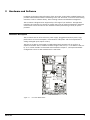
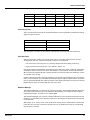
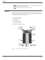
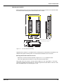
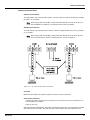
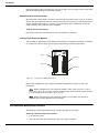
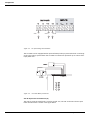
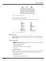
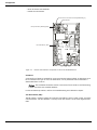
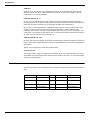
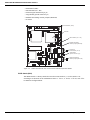
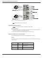
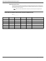
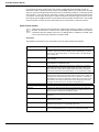
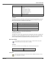
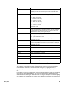
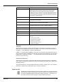
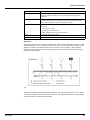
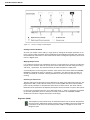
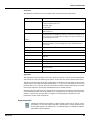
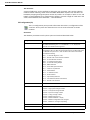
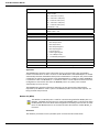
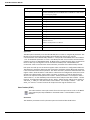
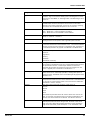
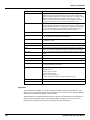
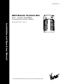
4
Configuration
The 8130 RTU is supported by a full range of I/O interfaces. I/O expansion modules are available
for connection to almost every type of signal encountered in industrial environments. Since
wiring to field devices depends on the I/O expansion module, the procedure will vary for each
device. The basic 8130 RTU is constructed as a Motherboard with connectors for up to four I/O
expansion modules.
Note Refer to the 8130 RTU Installation chapter for guidelines and procedures for using
the 8130 RTU in a hazardous location.
Note The channel numbering will usually be the same regardless of the I/O expansion
board. Channel 1 begins with the top left connector and Channel 17 begins with the top
right connector.
The I/O modules are either single-sized (4.5" by 5.1") or double-sized (4.5" by 10.3"). The I/O
expansion modules are listed below:
• Model 8201 16-Channel Digital In-/Out module (contacts, relays)
• Model 8203 Dual RS-485 Communication Interface module (Modbus, MTS, PetroSense)
• Model 8204 8-Channel Multi-Function module (contacts, relays, Pulse Totalizer, Analog
inputs)
• Model 8205 16-Channel Analog Input module (4-20 mA, 1-5V)
• Model 8207 8-Channel Analog Output module (4-20 mA, 0-20 mA, 1-5V)
• Model 8208 TIWAY Interface module (Texas Instruments (IT-111, IT-121, IT-150)
• Model 8210 Varec Mark/Space Interface module (Mark/Space Micro 4-wire Model 1800,
Model 1900, Model 4000, 2900 FTT)
• Model 8211 Current Loop Interface module (Whessoe Bus Protocol, GPE Protocol)
• Model 8212 Saab TRL/2 Interface module
• Model 8213 V1 Interface module (Varec TGM 3000, TGM 4000, Varec SG6000)
• Model 8214 Enraf Interface module (Enraf 811, 802/812, 854, 873)
• Model 8215 L&J Tankway Interface module (MCG 1000, MCG 1500, MCG 2000)
• Model 8216 LON Interface module (Barton Instruments Series 3500)
• Model 8217 Dual RS-232 Interface module
Configuration instructions for each I/O expansion board can be found in the following relevant
chapters.
Motherboard Description
The motherboard description is broken into three sections. Each section identifies the location
of the components on the motherboard. When necessary, a brief description of the component
is provided. These sections are listed below:
• Power Supply
• Switches and Indicators
• Communications
Varec, Inc.
21