1
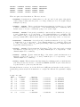
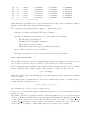
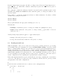
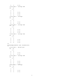
ATOM User Manual
Version 3.2, July 2002
Alberto Garcı́a
Universidad del Paı́s Vasco, Bilbao, SPAIN
[email protected] vfill
Contents
1 PREFACE
2
2 A PRIMER ON AB-INITIO PSEUDOPOTENTIALS
2
3 COMPILING THE PROGRAM
3
4 USING THE ATOM PROGRAM
3
4.1
All-electron calculations . . . . . . . . . . . . . . . . . . . . . . . . . . . . . . . .
3
4.2
Pseudopotential generation . . . . . . . . . . . . . . . . . . . . . . . . . . . . . .
5
4.2.1
Core Corrections . . . . . . . . . . . . . . . . . . . . . . . . . . . . . . . .
7
Pseudopotential test . . . . . . . . . . . . . . . . . . . . . . . . . . . . . . . . . .
8
4.3
5 APPENDIX: THE INPUT FILE
12
6 APPENDIX: INPUT FILE DIRECTIVES
15
1
1
PREFACE
ATOM is the name of a program originally written (circa 1982) by Sverre Froyen at the University of California at Berkeley, modified starting in 1990 by Norman Troullier and Jose Luis
Martins at the University of Minnesota, and currently maintained by Alberto Garcia ([email protected]), who added some features and made substantial structural changes to the
April 1990 (5.0) Minnesota version while at Berkeley and elsewhere.
Jose Luis Martins is maintaining his own version of the code:
{\tt http://bohr.inesc.pt/~jlm/pseudo.html
The program’s basic capabilities are:
• All-electron DFT atomic calculations for arbitrary electronic configurations.
• Generation of ab-initio pseudopotentials (several flavors).
• Atomic calculations in which the effect of the core is represented by a previously generated pseudopotential. These are useful to make sure that the pseudopotential correctly
reproduces the all-electron results for the valence complex.
2
A PRIMER ON AB-INITIO PSEUDOPOTENTIALS
Time constraints prevent the inclusion of this section in this first release of the ATOM manual.
But, in this case more than ever, there is a lot to be gained from reading the original literature...
Here are some basic references:
• Original idea of the ab-initio pseudopotential:
Kerker, J. Phys. C 13, L189-94 (1980)
Hamann, Schluter, Chiang, Phys. Rev. Lett. 43, 1494 (1979)
• More on HSC scheme:
Bachelet, Schluter, Phys. Rev. B 25, 2103 (1982)
Bachelet, Hamann, Schluter, Phys. Rev. B 26, 4199 (1982)
• Troullier-Martins elaboration of Kerker method:
Troullier, Martins, Phys. Rev. B 43, 1993 (1991)
Troullier, Martins, Phys. Rev. B 43, 8861 (1991)
• Core corrections:
Louie, Froyen, Cohen, Phys. Rev. B 26, 1738 (1982)
• The full picture of plane-wave pseudopotential ab-initio calculations:
W. E. Pickett, “Pseudopotential Methods in Condensed Matter Applications”, Computer
Physics Reports 9, 115 (1989)
M. C. Payne, M. P. Teter, D. C. Allan, T. A. Arias and J. D. Joannopoulos, “Iterative
minimization techniques for ab initio total-energy calculations: molecular dynamics and
conjugate gradients”, Rev. Mod. Phys. 64, 1045, (1992)
2
• Use in SIESTA:
J.M. Soler, E. Artacho, J.D. Gale, A. Garcia, J. Junquera, P. Ordejon, D. Sanchez-Portal,
“The SIESTA method for ab initio O(N) materials simulation”, Jour. Phys.: Condens.
Matter, 14, 2745-2779 (2002).
3
COMPILING THE PROGRAM
Edit makefile in the main source directory, and modify, if needed, the defaults for Fortran
compiler and auxiliary file containing date and time routines (not standard in Fortran77).
Type make. After a short while you will have the executable (called atm) in that same directory.
The program should work for any atom without recompilation.
Directory Tutorial in the source distribution contains a set of scripts to automate the process
of running ATOM and to analyze the results. The file-manipulation details involved in each
of the basic functions of all-electron calculations, generation of pseudopotentials, and testing of
the pseudopotentias, are taken care of by ae.sh, pg.sh, and pt.sh, respectively. These scripts
need to know where the ATOM executable atm is. If you have moved the Tutorial directory
around, or you do not have the source, the default location might not be right for you. The
easiest way to fix it is to define an environmental variable ATOM PROGRAM. Assuming atm is in
/somedir/somewhere, you would do:
ATOM_PROGRAM=/somedir/somewhere/atm ; export ATOM_PROGRAM
setenv ATOM_PROGRAM /somedir/somewhere/atm
# sh-derived shells
# csh-derived shells
Due to the shortcommings of the basic (GNUplot) plotting package used in the Tutorial section,
it is also necessary to copy some scripts from a central repository. Again, if the default does not
work for you, define the ATOM UTILS DIR variable:
ATOM_UTILS_DIR=/somewhere ; export ATOM_UTILS_DIR
setenv ATOM_UTILS_DIR /somewhere
4
4.1
# sh-derived shells
# csh-derived shells
USING THE ATOM PROGRAM
All-electron calculations
Assume we want to find the orbital eigenvalues, total energy, and/or charge density of Si in
its ground state. (You should now go to the Tutorial/All electron directory and try the
following.) Our input file is named si.ae.inp and contains the lines (see Sect. 5 for more
details):
ae Si ground state all-electron
Si
ca
0.0
3
2
3
0
2.00
0.00
3
1
2.00
0.00
#2345678901234567890123456789012345678901234567890
3
Ruler
We can run the calculation by using the ae.sh script. Following the layout of the Tutorial
directory, we will assume that the script is in the directory directly above the current one. We
run the script and go into the directory created for the calculation (named as the input file
without the extension .inp):
$ sh ../ae.sh si.ae.inp
==> Output data in directory si.ae
$ cd si.ae
$ ls
AECHARGE CHARGE RHO
charge.gplot
AEWFNR0
INP
ae.gplot charge.gps
AEWFNR1
OUT
ae.gps
vcharge.gplot
$
vcharge.gps
vspin.gplot
vspin.gps
We see some data files (those in all caps) and a few GNUPLOT plotting scripts1 .
The files are:
• INP: A copy of the input file for the calculation.
• OUT: Contains detailed information about the run.
• AECHARGE: Contains in four columns values of r, the “up” and “down” parts of the total
charge density, and the total core charge density (the charges multiplied by 4πr2 ). CHARGE
is exactly identical and is generated for backwards compatibility.
• RHO: Like CHARGE, but without the 4πr2 factor.
• AEWFNR0...AEWFNR3: All-electron valence wavefunctions as function of radius, for s, p, d,
and f valence orbitals (0, 1, 2, 3, respectively — some channels might not be available).
They include a factor of r, the s orbitals also going to zero at the origin.
It is interesting to peruse the OUT file. In particular, it lists the orbital eigenvalues (in Rydbergs,
as every other energy in the program):
nl
s
occ
1s
2s
2p
3s
3p
0.0
0.0
0.0
0.0
0.0
2.0000
2.0000
6.0000
2.0000
2.0000
eigenvalue
kinetic energy
-130.36911241
-10.14892694
-7.02876268
-0.79662742
-0.30705179
183.01377616
25.89954259
24.42537874
3.23745215
2.06135782
pot energy
-378.73491463
-71.62102169
-68.74331203
-17.68692611
-13.62572515
(For a relativistic or spin-polarized calculation, there would be “up” and “down” flags in the s
column above.)
The plotting scripts come in two flavors: .gplot for terminal use (default X11, use gnuplot
-persist), and .gps for postscript output.
For all-electron calculations, the relevant scripts (without .gplot or .gps extensions) are:
1
GNUPLOT is not a publication-quality package, and suffers from serious shortcomings, but it is free, and
installed almost everywhere. Hence we have chosen it as the lowest-common denominator for basic plotting
4
• charge: Charge density (separated core and valence contributions, multiplied by 4πr2 ).
• vcharge: Valence charge density (same normalization).
• ae: Orbital valence wavefunctions (radial part multiplied by r)
4.2
Pseudopotential generation
(You should now go to the Tutorial/Si directory and try the following.) We are going to generate a pseudopotential for Si, using the Troullier-Martins scheme. The calculation is relativistic
and we use the LDA (Ceperley-Alder flavor). The input file is named Si.tm2.inp and contains
the lines (see Sect. 5 for more details):
#
#
#
#
Pseudopotential generation for Silicon
pg: simple generation
pg
n=Si
3
3
3
3
4
Silicon
tm2
3.0
c=car
0.0
0.0
4
0
2.00
1
2.00
2
0.00
3
0.00
1.90
1.90
0.0
0.00
0.00
0.00
0.00
1.90
# PS flavor, logder R
# Symbol, XC flavor,{ |r|s}
0.0
0.0
0.0
# norbs_core, norbs_valence
# 3s2
# 3p2
# 3d0
# 4f0
1.90
0.00
0.00
#
# Last line (above):
#
rc(s)
rc(p)
rc(d)
rc(f)
rcore_flag rcore
#
#23456789012345678901234567890123456789012345678901234567890
Note the two extra lines with respect to an all-electron calculation. The pseudopotential core
radii for all channels are 1.90 bohrs. Even though they are nominally empty in the ground state,
we include the 3d and 4f states in order to generate the corresponding pseudopotentials.
We can run the calculation by using the pg.sh script. Following the layout of the Tutorial
directory, we will assume that the script is in the directory directly above the current one. We
run the script and go into the directory created for the calculation (named as the input file
without the extension .inp):
$ sh ../pg.sh Si.tm2.inp
==> Output data in directory Si.tm2
==> Pseudopotential in Si.tm2.vps and Si.tm2.psf
$ cd Si.tm2
$ ls [A-Z]*
# show only the data filesAE
CHARGE AEWFNR3
PSLOGD3 PSPOTR3 PSWFNR3
AELOGD0
CHARGE
PSPOTQ0 PSWFNQ0 RHO
AELOGD1
INP
PSPOTQ1 PSWFNQ1 SCRPSPOTR0
AELOGD2
OUT
PSPOTQ2 PSWFNQ2 SCRPSPOTR1
5
AELOGD3
AEWFNR0
AEWFNR1
AEWFNR2
PSCHARGE
PSLOGD0
PSLOGD1
PSLOGD2
PSPOTQ3
PSPOTR0
PSPOTR1
PSPOTR2
PSWFNQ3
PSWFNR0
PSWFNR1
PSWFNR2
SCRPSPOTR2
SCRPSPOTR3
VPSFMT
VPSOUT
There are quite a few data files now. The new ones are:
• PSCHARGE: Contains in four columns values of r, the “up” and “down” parts of the pseudo
valence charge density, and the pseudo core charge density (see Sect. 4.2.1) (the charges
multiplied by 4πr2 ).
• PSWFNR0...PSWFNR3: Valence pseudowavefunctions as function of radius, for s, p, d, and
f valence orbitals (0, 1, 2, 3, respectively — some channels might not be available). They
include a factor of r, the s orbitals also going to zero at the origin.
• PSPOTR0...PSPOTR3: Ionic pseudopotentials (i.e. unscreened) as a function of r, for s, p,
d, and f channels (0, 1, 2, 3, respectively — some channels might not be available). The
last column is −2Zps /r, that is, the Coulomb potential of the pseudo atom. All the ionic
pseudopotentials tend to this Coulomb tail for r beyond the range of the core electrons.
• SCRPSPOTR0...SCRPSPOTR3: Screened pseudopotentials as a function of r, for s, p, d, and
f channels (0, 1, 2, 3, respectively — some channels might not be available). They tend
to −2Zion /r for large r, where Zion is the global charge of the reference configuration used
in pseudopotential generation.
• PSPOTQ0...PSPOTQ3: Fourier transform V (q) (times q 2 /Zps ) of the ionic pseudopotentials
as a function of q (in bohr−1 ), for s, p, d, and f channels (0, 1, 2, 3, respectively — some
channels might not be available).
• PSWFNQ0...PSWFNQ3: Fourier transform Ψ(q) of the valence pseudowavefunctions as a
function of q (in bohr−1 ), for s, p, d, and f channels (0, 1, 2, 3, respectively — some
channels might not be available).
• VPSOUT, VPSFMT: Files (formatted and unformatted) containing pseudopotential information. They are used for ab-initio codes such as SIESTA and PW. Copies of these files are
deposited in the top directory after the run.
The OUT file has two sections, one for the all-electron (AE) run, and another for the pseudopotential (PS) generation itself. It is instructive to compare the AE and PS eigenvalues. Simply
do
$ grep ’&v’ OUT
ATM3
12-JUL-02
Silicon
3s
0.5
2.0000
-0.79937161
3p -0.5
0.6667
-0.30807129
3p
0.5
1.3333
-0.30567134
3d -0.5
0.0000
0.00000000
3d
0.5
0.0000
0.00000000
4f -0.5
0.0000
0.00000000
4f
0.5
0.0000
0.00000000
---------------------------- &v
3s
0.5
2.0000
-0.79936061
6
0.00000000
0.00000000
0.00000000
0.00000000
0.00000000
0.00000000
0.00000000
-17.74263363
-13.66178958
-13.60785822
-0.27407047
-0.27407047
-0.26482365
-0.26482365
0.50555315
-3.74113059
3p -0.5
0.6667
-0.30804995
3p
0.5
1.3333
-0.30565760
3d -0.5
0.0000
0.00000000
3d
0.5
0.0000
0.00000000
4f -0.5
0.0000
0.00000000
4f
0.5
0.0000
0.00000000
---------------------------- &v
0.77243805
0.76702460
0.00140505
0.00140505
0.00243411
0.00243411
-3.26356669
-3.25197500
-0.07847269
-0.07847269
-0.07586534
-0.07586534
(The AE and PS eigenvalues are not exactly identical because the pseudopotentials are changed
slightly to make them approach their limit tails faster).
The relevant plotting scripts (without .gplot or .gps extensions) are:
• charge: It compares the AE and PS charge densities.
• pseudo: A multi-page plot showing, on one page/window per channel:
– The AE and PS wavefunctions
– The AE and PS logarithmic derivatives.
– The real-space pseudopotential
– The Fourier-transformed pseudopotential (times q 2 /Zps )
• pots: All the real-space pseudopotentials.
• scrpots: Comparison of the screened and unscreened pseudopotentials.
4.2.1
Core Corrections
The program can generate pseudopotentials with the non-linear exchange-correlation correction
proposed in S. G. Louie, S. Froyen, and M. L. Cohen, Phys. Rev. B 26, 1738 (1982).
In the traditional approach (which is the default for LDA calculations), the pseudocore charge
density equals the charge density outside a given radius rpc , and has the smooth form
ρpc (r) = Ar sin(br)
inside that radius. A smooth matching is provided with suitable A and b parameters calculated
by the program.
A new scheme has been implemented to fix some problems in the generation of GGA pseudopotentials. The smooth function is now
ρpc (r) = r2 exp (a + br2 + cr4 )
and derivatives up to the second are continuous at rpc .
To use core corrections in the pseudopotential generation the jobcode in the first line should be
pe instead of pg.
The radius rpc should be given in the sixth slot in the last input line (see above). If it is negative
or zero (or blank), the radius is then computed using the fifth number in that line (rcore flag,
see the example input file above) and the following criterion: at rpc the core charge density
equals rcore flag*(valence charge density). It is highly recommended to set an explicit value
for the pseudocore radius rpc , rather than letting the program provide a default.
7
If rcore flag is input as negative, the full core charge is used. If rcore flag is input as zero,
it is set equal to one, which will be thus the default if pe is given but no numbers are given for
these two variables.
The output file contains the radius used and the A (a) and b (and c) parameters used for the
matching. The VPSOUT and VPSFMT files will contain the pseudocore charge in addition to the
pseudopotential.
It is possible to override the default (new scheme for GGA calculations, old scheme for LDA
calculations) by using the directives
%define NEW_CC
%define OLD_CC
The program will issue the appropriate warnings. (See Sect. 5)
Relevant files:
• PSCHARGE: Contains the pseudocore charge in column four. (multiplied by 4πr2 ).
• COREQ: Fourier transform of the pseudocore charge density ρpc (q) in units of electrons,
with q in bohr−1 .
Useful plotting scripts (without .gplot or .gps extensions) are:
• charge: Shows also the pseudocore charge.
• coreq: Shows the Fourier transform of the pseudocore charge.
4.3
Pseudopotential test
While it is helpful to “have a look” at the plots of the pseudopotential generation to get a feeling
for its quality, there is no substitute for a proper transferability testing. A pseudopotential
with good transferability will reproduce the all-electron energy levels and wavefunctions in arbitrary environments, (i.e., in the presence of charge transfer, which always takes place when
forming solids and molecules). We know that norm conservation guarantees a certain degree of
transferability (usually seen clearly in the plot of the logarithmic derivative), but we can get
a better assessment by performing all-electron and “pseudo” calculations on the same series of
atomic configurations, and comparing the eigenvalues and excitation energies.
In the same Tutorial/Si directory we can find file Si.test.inp, containing the concatenation
of ten jobs. The first five are all-electron (ae) calculations, and the last five, pseudopotential
test (pt) runs for the same configurations:
#
# All-electron calculations for a series of Si configurations
#
ae Si Test -- GS 3s2 3p2
Si
ca
0.0
3
2
3
0
2.00
8
3
1
ae Si Test
Si
ca
0.0
3
3
3
0
3
1
3
2
ae Si Test
Si
ca
0.0
3
2
3
0
3
1
ae Si Test
Si
ca
0.0
3
3
3
0
3
1
3
2
ae Si Test
Si
ca
0.0
3
3
3
0
3
1
3
2
2.00
-- 3s2 3p1 3d1
2.00
1.00
1.00
-- 3s1 3p3
1.00
3.00
-- 3s1 3p2 3d1
1.00
2.00
1.00
-- 3s0 3p3 3d1
0.00
3.00
1.00
#
# Pseudopotential test calculations
#
pt Si Test -- GS 3s2 3p2
Si
ca
0.0
3
2
3
0
2.00
3
1
2.00
pt Si Test -- 3s2 3p1 3d1
Si
ca
0.0
3
3
3
0
2.00
3
1
1.00
3
2
1.00
pt Si Test -- 3s1 3p3
Si
ca
0.0
3
2
3
0
1.00
3
1
3.00
9
pt Si Test -- 3s1 3p2 3d1
Si
ca
0.0
3
3
3
0
1.00
3
1
2.00
3
2
1.00
pt Si Test -- 3s0 3p3 3d1
Si
ca
0.0
3
3
3
0
0.00
3
1
3.00
3
2
1.00
The configurations differ in the promotion of electrons from one level to another (it is also
possible to transfer fractions of an electron).
We can run the file by using the pt.sh script. Following the layout of the Tutorial directory,
we will assume that the script is in the directory directly above the current one. We need to
give it two arguments: the calculation input file, and the file containing the pseudopotential we
want to test. Let’s make the latter Si.tm2.vps:
$ sh ../pt.sh Si.test.inp Si.tm2.vps
$ sh ../pt.sh Si.test.inp Si.tm2.vps
==> Output data in directory Si.test-Si.tm2
$ cd Si.test-Si.tm2/
$ ls [A-Z]*
AECHARGE AEWFNR1 CHARGE OUT
PTWFNR0
AEWFNR0
AEWFNR2 INP
PTCHARGE PTWFNR1
PTWFNR2
RHO
VPSIN
The working directory is named after both the test and pseudopotential files. It contains several
new files:
• VPSIN: A copy of the pseudopotential file to be tested.
• PTCHARGE: Contains in four columns values of r, the “up” and “down” parts of the pseudo
valence charge density, and the pseudo core charge density (see Sect. 4.2.1) (the charges
multiplied by 4πr2 ).
• PTWFNR0...PTWFNR3: Valence pseudowavefunctions as function of radius, for s, p, d, and
f valence orbitals (0, 1, 2, 3, respectively — some channels might not be available). They
include a factor of r, the s orbitals also going to zero at the origin.
The OUT file has two sections, one for the all-electron (AE) runs, and another for the pseudopotential tests (PT). At the end of each series of runs there is a table showing the excitation
energies. A handy way to compare the AE and PT energies is:
$ grep ’&d’ OUT
[...elided...]
&d total energy differences in series
10
&d
1
2
3
4
5
&d 1
0.0000
&d 2
0.4308
0.0000
&d 3
0.4961
0.0653
0.0000
&d 4
0.9613
0.5305
0.4652
0.0000
&d 5
1.4997
1.0689
1.0036
0.5384
0.0000
*----- End of series ----* spdfg &d&v
ATM3
12-JUL-02
Si Test -- GS 3s2 3p2
ATM3
12-JUL-02
Si Test -- 3s2 3p1 3d1
ATM3
12-JUL-02
Si Test -- 3s1 3p3
ATM3
12-JUL-02
Si Test -- 3s1 3p2 3d1
ATM3
12-JUL-02
Si Test -- 3s0 3p3 3d1
&d total energy differences in series
&d
1
2
3
4
5
&d 1
0.0000
&d 2
0.4299
0.0000
&d 3
0.4993
0.0694
0.0000
&d 4
0.9635
0.5336
0.4642
0.0000
&d 5
1.5044
1.0745
1.0051
0.5409
0.0000
*----- End of series ----* spdfg &d&v
The tables (top AE, bottom PT) give the cross-excitations among all configurations. Typically,
one should be all right if the AE-PT differences are not much larger than 1 mRy.
You can also compare the AE and PT eigenvalues. Simply do
$ grep ’&v’ OUT | grep s
ATM3
12-JUL-02
Si Test -- GS 3s2 3p2
3s
0.0
2.0000
-0.79662742
3.23745215
ATM3
12-JUL-02
Si Test -- 3s2 3p1 3d1
3s
0.0
2.0000
-1.08185979
3.53885995
ATM3
12-JUL-02
Si Test -- 3s1 3p3
3s
0.0
1.0000
-0.85138783
3.35438895
ATM3
12-JUL-02
Si Test -- 3s1 3p2 3d1
3s
0.0
1.0000
-1.11431855
3.62997498
ATM3
12-JUL-02
Si Test -- 3s0 3p3 3d1
3s
0.0
0.0000
-1.14358268
3.71462770
*----- End of series ----* spdfg &d&v
ATM3
12-JUL-02
Si Test -- GS 3s2 3p2
1s
0.0
2.0000
-0.79938037
0.50556261
ATM3
12-JUL-02
Si Test -- 3s2 3p1 3d1
1s
0.0
2.0000
-1.08384468
0.55070398
ATM3
12-JUL-02
Si Test -- 3s1 3p3
1s
0.0
1.0000
-0.85392666
0.52020429
ATM3
12-JUL-02
Si Test -- 3s1 3p2 3d1
1s
0.0
1.0000
-1.11546463
0.56048425
ATM3
12-JUL-02
Si Test -- 3s0 3p3 3d1
1s
0.0
0.0000
-1.14353959
0.56945741
*----- End of series ----* spdfg &d&v
-17.68692611
-18.40569836
-17.96219240
-18.60814708
-18.79448684
-3.74114712
-3.81988817
-3.76852577
-3.83646615
-3.85106049
(and similarly for p, d, and f , if desired). Again, the typical difference should be of around
11
1 mRyd for a “good” pseudopotential. (The real proof of good transferability, remember, can
only come from a molecular or solid-state calculation). Note that the PT levels are labeled
starting from principal quantum number 1.
The relevant plotting scripts (without .gplot or .gps extensions) are:
• charge: It compares the AE and PT charge densities.
• pt: Compares the valence all-electron and pseudo-wavefunctions.
5
APPENDIX: THE INPUT FILE
For historical reasons, the input file is in a rigid column format. Fortunately, most of the column
fields line up, so the possibility of errors is reduced. We will begin by describing in detail a very
simple input file for an all-electron calculation for the ground state of Si. More examples can
be found in the Tutorial directory.
The file itself is:
#
#
#
Comments allowed here
ae Si ground state all-electron
Si
car
0.0
3
2
3
0
2.00
0.00
3
1
2.00
0.00
#
# Comments allowed here
#
#2345678901234567890123456789012345678901234567890
Ruler
• The first line specifies:
– The calculation code (ae here stands for “all-electron”).
– A title for the job (here Si ground state all-electron).
(format 3x,a2,a50)
• Second line:
– Chemical symbol of the nucleus (here Si, obviously)
– Exchange-correlation type. Here, ca stands for Ceperley-Alder. Other options (to be
removed) are wi (Wigner), hl (Hedin-Lundqvist), gl (Gunnarson-Lundqvist), and
bh (von Barth-Hedin). The “best” LDA choice should be ca. It is also possible to
use a gradient-corrected functional: pb indicates use of the GGA scheme by Perdew,
Burke, and Ernzerhof (PRL 77, 3865 (1996).
– The character r next to ca is a flag to perform the calculation relativistically, that
is, solving the Dirac equation instead of the Schrodinger equation. The full range of
options is:
12
∗ s : Spin-polarized calculation, non-relativistic.
∗ r: Relativistic calculation, obviously polarized.
∗ (blank) : Non-polarized (spin ignored), non-relativistic calculation.
(format 3x,a2,3x,a2,a1,2x)
• Third line. Its use is somewhat esoteric and for most calculations it should contain just a
0.0 in the position shown.
The rest of the file is devoted to the specification of the electronic configuration:
• Fourth line:
Number of core and valence orbitals. For example, for Si, we have 1s, 2s, and 2p in the
core (a total of 3 orbitals), and 3s and 3p in the valence complex (2 orbitals).
(format 2i5)
• Fifth, sixth... lines: (there is one line for each valence orbital)
– n (principal quantum number)
– l (angular momentum quantum number)
– Occupation of the orbital in electrons.
(format 2i5,2f10.3)
(There are two f input descriptors to allow the input of “up” and “down” occupations in
spin-polarized calculations (see example below))
Comments or blank lines may appear in the file at the beginning and at the end. It is possible
to perform two or more calculations in succession by simply concatenating blocks as the one
described above. For example, the following file is used to study the ground state of N and an
excited state with one electron promoted from the 2s to the 2p orbital taking into account the
spin polarization:
#
ae N ground state all-electron
N
cas
0.0
1
2
2
0
2.00
0.00
2
1
3.00
0.00
#
#
#
Second calculation starts here
ae N 1s2 2s1 2p4 all-electron
N
cas
0.0
1
2
2
0
1.00
0.00
2
1
3.00
1.00
#2345678901234567890123456789012345678901234567890
13
Ruler
The different treatment of core and valence orbitals in the input for an all-electron calculation
is purely cosmetic. The program “knows” how to fill the internal orbitals in the right order, so
it is only necessary to give their number. That is handy for heavy atoms... Overzealous users
might want to check the output to make sure that the core orbitals are indeed correctly treated.
For a pseudopotential test calculation, the format is exactly the same, except that the job
code is pt instead of ae.
For a pseudopotential generation run, in addition to the electronic configuration chosen for
the generation of the pseudopotentials (which is input in the same manner as above), one has
to specify the “flavor” (generation scheme) and the set of core radii rc for the construction of
the pseudowavefunction. Here is an example for Si using the Hamann-Schluter-Chiang scheme:
#
pg Si Pseudopotencial
hsc
2.00
Si
ca
0
3
3
3
0
2.00
3
1
0.50
3
2
0.50
1.12
1.35
1.17
0.0
0.0
0.0
#
#23456789012345678901234567890123456789012345678901234567890
---------------------------------------
Ruler
Apart from the pg (pseudopotential generation) job code in the first line, there are two extra
lines:
• Second line:
Flavor and radius at which to compute logarithmic derivatives for test purposes.
hsc
The flavor can be one of : ker
tm2
Hamann-Schluter-Chiang
Kerker
Improved Troullier-Martins
The ker and tm2 schemes can get away with larger rc , due to their wavefunction matching
conditions.
(format 8x, a3, f9.3)
• The last line (before the blank line) specifies:
– The values of the rc in atomic units (bohrs) for the s, p, d, and f orbitals (it is a good
practice to input the valence orbitals in the order of increasing angular momentum,
so that there is no possible confusion).
(format 4f10.5)
– Two extra fields (2f10.5) which are relevant only if non-local core corrections are used
(see Sect 4.2.1).
In the hsc example above, only s ,p, and d rc ’s are given. Here is an example for Silicon in
which we are only interested in the s and p channels for our pseudopotential, and use the Kerker
scheme:
14
#
pg Si Kerker
ker
Si
ca
0
3
3
3
0
3
1
1.80
generation
2.00
2.00
2.00
1.80
0.00
0.0
0.0
0.0
#23456789012345678901234567890123456789012345678901234567890
Ruler
This completes the discussion of the more common features of the input file. See the Appendix 6
for more advanced options.
6
APPENDIX: INPUT FILE DIRECTIVES
The fixed format can be a source of desperation for the beginner, and its rigidity means that it
is not easy to add new items to the input. For this purpose, the program takes another route:
several variables can be entered in a specially flexible format by means of directives at the top
of the file. For example
%define NEW_CC
.... rest of the input file
would signal that we want to use a new core-correction scheme.
There are two kinds of directives, with syntax:
%VARIABLE=value
%define NAME
In the first case we assign the value value to the variable VARIABLE. The program can look at
the value via a special subroutine call.
The second form is a bit more abstract, but can be understood as assigning a special “existence”
value of 1 to the variable NAME. Again, the program can check for the existence of the variable
via a special subroutine call.
Currently, the program understands the following NAMEs:
• COMPAT UCB: Revert to the standard circa 1990 UCB values. Note that these correspond
to the first released version of Jose Luis Martins code, not to the old Froyen version. (The
defaults are: use a denser grid up to larger radii. Use a larger value for the pseudopotential
cutoff point. Use the Soler-Balbas XC package)
• NEW CC: New core-correction scheme
• OLD CC: Old core-correction scheme (see Sect. 4.2.1)
• NO PS CUTOFFS: Avoid cutting off the tails of the pseudopotentials.
15