1
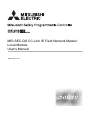
MELSEC-QS CC-Link IE Field Network Master/
Local Module
User's Manual
-QS0J71GF11-T2
SAFETY PRECAUTIONS
(Read these precautions before using this product.)
Before using this product, please read this manual and the relevant manuals carefully and pay full attention
to safety to handle the product correctly.
The precautions given in this manual are concerned with this product only. For the safety precautions of the
programmable controller system, refer to the user's manual for the CPU module used.
In this manual, the safety precautions are classified into two levels: "
WARNING" and "
CAUTION".
WARNING
Indicates that incorrect handling may cause hazardous conditions,
resulting in death or severe injury.
CAUTION
Indicates that incorrect handling may cause hazardous conditions,
resulting in minor or moderate injury or property damage.
Under some circumstances, failure to observe the precautions given under "
CAUTION" may lead to
serious consequences.
Observe the precautions of both levels because they are important for personal and system safety.
Make sure that the end users read this manual and then keep the manual in a safe place for future
reference.
[Design Precautions]
WARNING
● When a safety programmable controller detects an error in an external power supply or a failure in
programmable controller main module, it turns off all the outputs. Create an external circuit to securely
stop the power of hazard by turning off the outputs. Incorrect configuration may result in an accident.
● To inhibit restart without manual operation after safety functions was performed and outputs were
turned off, create an interlock program which uses a reset button for restart.
● If CC-Link IE Field Network error has been detected, create a sequence program that turns off the
outputs in the program. If the CC-Link IE Field Network is restored with the outputs on, it may
suddenly operate and result in an accident.
[Design Precautions]
CAUTION
● Do not bunch the wires of external devices or communication cables together with the main circuit or
power lines, or install them close to each other. They should be installed 100 mm (3.94 inch) or more
from each other. Not doing so could result in noise that would cause malfunctions.
1
[Installation Precautions]
CAUTION
● Use a safety programmable controller in the environment that meets the general specifications
described in the QSCPU User's Manual (Hardware Design, Maintenance and Inspection). Using this
programmable controller in an environment outside the range of the general specifications could
result in electric shock, fire, erroneous operation, and damage to or deterioration of the product.
● While pressing the installation lever located at the bottom of module, insert the module fixing tab into
the fixing hole in the base unit until it stops. Then, securely mount the module with the fixing hole as a
supporting point. Incorrect loading of the module can cause a failure or drop. Secure the module to
the base unit with screws. Tighten the screw in the specified torque range. If the screws are too loose,
it may cause a drop of the screw or module. Overtightening may cause a drop due to the damage of
the screw or module.
● Completely turn off the external supply power used in the system before mounting or removing the
module. Not doing so could result in damage to the product.
● Do not directly touch the module's conductive parts or electronic components. Doing so may cause
malfunctions or a failure.
[Wiring Precautions]
WARNING
● Be sure to shut off all phases of the external supply power used by the system before wiring. Not
completely turning off all power could result in electric shock or damage to the product.
● When energizing or operating the module after installation or wiring, be sure to close the attached
terminal cover. Not doing so may result in electric shock.
2
[Wiring Precautions]
CAUTION
● Tighten a module fixing screw within the specified torque range. If the module fixing screw is too
loose, it may cause a drop of the screw or module. Overtightening the screw may cause a drop due to
the damage of the screw or module.
● Be sure there are no foreign substances such as sawdust or wiring debris inside the module. Such
debris could cause a fire, failure, or malfunctions.
● The module has an ingress prevention label on its top to prevent foreign matter, such as wire chips,
from entering the module during wiring. Do not peel this label during wiring. Before starting system
operation, be sure to peel this label because of heat dissipation.
● Be sure to fix the communication cables or power cables by ducts or clamps when connecting them to
the module. Failure to do so may cause damage of the module or cables due to a wobble,
unintentional shifting, or accidental pull of the cables, or malfunctions due to poor contact of the cable.
● When removing the connected communication cables or power cables, do not pull the cable with
grasping the cable part. Pulling the cable connected to a module may result in malfunctions or
damage of the module or cable.
● For the cables to be used in CC-Link IE Field Network, use the ones specified by the manufacturer.
Otherwise, the performance of CC-Link IE Field Network is not guaranteed. As to the maximum
overall cable length and station - to station cable length, follow the specifications described in the
MELSEC-QS CC-Link IE Field Network Master/Local Module User's Manual. If not following the
specification, the normal data transmission is not guaranteed.
3
[Startup and Maintenance Precautions]
WARNING
● Turn off all phases of the external supply power used in the system when cleaning the module or
retightening the module fixing screws. Not doing so could result in electric shock.
Tighten a fixing screw within the specified torque range. If the module fixing screw is too loose, it may
cause a drop of the screw or module. Overtightening the screw may cause a drop due to the damage
of the screw or module.
[Startup and Maintenance Precautions]
CAUTION
● Do not disassemble or modify the modules. Doing so could cause a failure, malfunctions, injury, or
fire. If the product is repaired or remodeled by other than the specified FA centers or us, the warranty
is not covered.
● Completely turn off the external supply power used in the system before mounting or removing the
module. Not doing so may result in a failure or malfunctions of the module.
● Restrict the mounting/removal of a module, base unit, and terminal block up to 50 times
(IEC61131-2 compliant), after the first use of the product.
Failure to do so may cause the module to malfunction due to poor contact of connector.
● Before touching the module, always touch grounded metal, etc. to discharge static electricity from
human body, etc. Not doing so may result in a failure or malfunctions of the module.
[Disposal Precautions]
CAUTION
● When disposing of this product, treat it as industrial waste. When disposing of batteries, separate
them from other wastes according to the local regulations. (For details of the Battery Directive in EU
member states, refer to the QSCPU User's Manual (Hardware Design, Maintenance and Inspection).)
4
CONDITIONS OF USE FOR THE PRODUCT
(1) Although MELCO has obtained the certification for Product's compliance to the international safety
standards IEC61508, EN954-1/ISO13849-1 from TUV Rheinland, this fact does not guarantee that
Product will be free from any malfunction or failure. The user of this Product shall comply with any
and all applicable safety standard, regulation or law and take appropriate safety measures for the
system in which the Product is installed or used and shall take the second or third safety measures
other than the Product. MELCO is not liable for damages that could have been prevented by
compliance with any applicable safety standard, regulation or law.
(2) MELCO prohibits the use of Products with or in any application involving, and MELCO shall not be
liable for a default, a liability for defect warranty, a quality assurance, negligence or other tort and a
product liability in these applications.
(a) power plants,
(b) trains, railway systems, airplanes, airline operations, other transportation systems,
(c) hospitals, medical care, dialysis and life support facilities or equipment,
(d) amusement equipments,
(e) incineration and fuel devices,
(f) handling of nuclear or hazardous materials or chemicals,
(g) mining and drilling,
(h) and other applications where the level of risk to human life, health or property are elevated.
5
INTRODUCTION
Thank you for purchasing the Mitsubishi MELSEC-QS series programmable controllers.
This manual describes the overview of the CC-Link IE Field Network, and operating procedure, system configuration,
parameter setting, functions, programming, and troubleshooting of the QS0J71GF11-T2, CC-Link IE Field Network
master/local module (hereafter abbreviated as master/local module).
Before using this product, please read this manual and the relevant manuals carefully and develop familiarity with the
functions and performance of the MELSEC-QS series programmable controller to handle the product correctly.
When applying the program examples introduced in this manual to the actual system, ensure the applicability and
confirm that it will not cause system control problems.
Please make sure that the end users read this manual.
COMPLIANCE WITH THE EMC, LOW VOLTAGE, AND
MACHINERY DIRECTIVES
(1) Method of ensuring compliance
To ensure that Mitsubishi programmable controllers maintain EMC, Low Voltage, and Machinery Directives when
incorporated into other machinery or equipment, certain measures may be necessary. Please refer to one of the
following manuals.
• QSCPU User's Manual (Hardware Design, Maintenance and Inspection)
• Safety Guidelines
(This manual is included with the base unit.)
The CE mark on the side of the programmable controller indicates compliance with EMC, Low Voltage, and
Machinery Directives.
(2) For the product
This product complies with the EMC, Low Voltage, and Machinery Directives. Before using this product, please
read this manual, the relevant manuals, the manuals for standard programmable controllers, and the safety
standards carefully and pay full attention to safety to handle the product correctly.
The descriptions are based on the requirements of the Directives and the harmonized standards. However, they
do not guarantee that the entire machinery constructed according to the descriptions complies with the EMC,
Low Voltage, and Machinery Directives.
The manufacture of the machinery must determine the testing method for compliance and declare conformity to
the EMC, Low Voltage, and Machinery Directives.
6
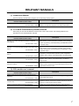
RELEVANT MANUALS
(1) Introduction Manual
Read the following manual before designing and constructing a safety system.
Manual name
Description
<manual number (model code)>
Safety Application Guide
Explains the overview, construction method, laying and wiring
<SH-080613ENG, 13JR90>
examples, and application programs of the safety-related system.
(2) CC-Link IE Field Network (relevant) manuals
When using CC-Link IE Field Network for the first time, refer to this manual. The following table lists and
describes CC-Link IE Field Network manuals.
Manual name
Description
<manual number (model code)>
MELSEC-Q CC-Link IE Field Network Master/Local Module
User's Manual
<SH-080917ENG, 13JZ47>
MELSEC-L CC-Link IE Field Network Master/Local Module User’s
Manual
<SH-080972ENG, 13JZ54>
MELSEC-L CC-Link IE Field Network Head Module User's
Manual
<SH-080919ENG, 13JZ48>
CC-Link IE Field Network Ethernet Adapter Module User's Manual
<SH-080939ENG, 13JZ50>
Overview of CC-Link IE Field Network, and specifications, procedures
before operation, system configuration, installation, wiring, settings,
functions, programming, and troubleshooting of the MELSEC-Q series
master/local module
Overview of CC-Link IE Field Network, and specifications, procedures
before operation, system configuration, installation, wiring, settings,
functions, programming, and troubleshooting of the MELSEC-L series
master/local module
Specifications, procedures before operation, system configuration,
installation, wiring, settings, and troubleshooting of the head module
Specifications, procedures before operation, system configuration,
installation, wiring, settings, and troubleshooting of the Ethernet
adapter module
CC-Link IE Field Network Interface Board User's Manual (For
Specifications, procedures before operation, system configuration,
SW1DNC-CCIEF-B)
settings, functions, programming, and troubleshooting of the CC-Link
<SH-080980ENG, 13JZ58>
IE Field Network interface board
(3) CPU module user's manual
Manual name
<manual number (model code)>
QSCPU User's Manual (Hardware Design, Maintenance and
Inspection)
<SH-080626ENG, 13JR92>
QSCPU User's Manual (Function Explanation, Program
Fundamentals)
<SH-080627ENG, 13JR93>
QSCPU Programming Manual (Common Instructions)
<SH-080628ENG, 13JW01>
Description
Explains the specifications of the QSCPU, safety power supply
module, safety base unit, etc.
Explains the functions, programming methods, devices, etc. that are
necessary to create programs with the QSCPU.
Explains how to use the sequence instructions, basic instructions,
application instructions, and QSCPU dedicated instructions.
7
(4) Operating manual
Manual name
<manual number (model code)>
GX Developer Version 8 Operating Manual
Description
Explains the online functions of GX Developer, such as the
<SH-080373E, 13JU41> programming, printout, monitoring, and debugging methods.
GX Developer Version 8 Operating Manual (Safety Programmable
Controller)
<SH-080576ENG, 13JU53>
8
Explains the functions of GX Developer that are added or changed to
support the safety programmable controller.
Memo
9
CONTENTS
CONTENTS
SAFETY PRECAUTIONS . . . . . . . . . . . . . . . . . . . . . . . . . . . . . . . . . . . . . . . . . . . . . . . . . . . . . . . . . . . . . 1
CONDITIONS OF USE FOR THE PRODUCT . . . . . . . . . . . . . . . . . . . . . . . . . . . . . . . . . . . . . . . . . . . . . 5
INTRODUCTION . . . . . . . . . . . . . . . . . . . . . . . . . . . . . . . . . . . . . . . . . . . . . . . . . . . . . . . . . . . . . . . . . . . . 6
COMPLIANCE WITH THE EMC, LOW VOLTAGE, AND MACHINERY DIRECTIVES . . . . . . . . . . . . . . . 6
RELEVANT MANUALS . . . . . . . . . . . . . . . . . . . . . . . . . . . . . . . . . . . . . . . . . . . . . . . . . . . . . . . . . . . . . . . 7
MANUAL PAGE ORGANIZATION . . . . . . . . . . . . . . . . . . . . . . . . . . . . . . . . . . . . . . . . . . . . . . . . . . . . . . 14
TERM. . . . . . . . . . . . . . . . . . . . . . . . . . . . . . . . . . . . . . . . . . . . . . . . . . . . . . . . . . . . . . . . . . . . . . . . . . . . 15
PACKING LIST . . . . . . . . . . . . . . . . . . . . . . . . . . . . . . . . . . . . . . . . . . . . . . . . . . . . . . . . . . . . . . . . . . . . 18
CHAPTER 1 CC-Link IE FIELD NETWORK
1.1
CC-Link IE Field Network . . . . . . . . . . . . . . . . . . . . . . . . . . . . . . . . . . . . . . . . . . . . . . . . . . . . . 19
1.2
Master/Local Modules. . . . . . . . . . . . . . . . . . . . . . . . . . . . . . . . . . . . . . . . . . . . . . . . . . . . . . . . 22
CHAPTER 2 PART NAMES
30
CHAPTER 3 SPECIFICATIONS
33
3.1
General Specifications . . . . . . . . . . . . . . . . . . . . . . . . . . . . . . . . . . . . . . . . . . . . . . . . . . . . . . . 33
3.2
Performance Specifications . . . . . . . . . . . . . . . . . . . . . . . . . . . . . . . . . . . . . . . . . . . . . . . . . . . 33
3.3
Function List . . . . . . . . . . . . . . . . . . . . . . . . . . . . . . . . . . . . . . . . . . . . . . . . . . . . . . . . . . . . . . . 35
3.3.1
Using the master/local module as a master station (safety station) . . . . . . . . . . . . . . . . . . . . 35
3.3.2
Using the master/local module as a local station . . . . . . . . . . . . . . . . . . . . . . . . . . . . . . . . . . 38
3.4
List of I/O Signals . . . . . . . . . . . . . . . . . . . . . . . . . . . . . . . . . . . . . . . . . . . . . . . . . . . . . . . . . . . 40
3.5
List of Buffer Memory Addresses . . . . . . . . . . . . . . . . . . . . . . . . . . . . . . . . . . . . . . . . . . . . . . . 42
CHAPTER 4 PROCEDURES BEFORE OPERATION
45
CHAPTER 5 SYSTEM CONFIGURATION
47
5.1
5.2
5.3
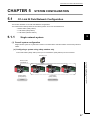
CC-Link IE Field Network Configuration . . . . . . . . . . . . . . . . . . . . . . . . . . . . . . . . . . . . . . . . . . 47
5.1.1
Single network system . . . . . . . . . . . . . . . . . . . . . . . . . . . . . . . . . . . . . . . . . . . . . . . . . . . . . . 47
5.1.2
Multi-network system . . . . . . . . . . . . . . . . . . . . . . . . . . . . . . . . . . . . . . . . . . . . . . . . . . . . . . . 55
Network Components . . . . . . . . . . . . . . . . . . . . . . . . . . . . . . . . . . . . . . . . . . . . . . . . . . . . . . . . 56
5.2.1
Cables . . . . . . . . . . . . . . . . . . . . . . . . . . . . . . . . . . . . . . . . . . . . . . . . . . . . . . . . . . . . . . . . . . 56
5.2.2
Hubs. . . . . . . . . . . . . . . . . . . . . . . . . . . . . . . . . . . . . . . . . . . . . . . . . . . . . . . . . . . . . . . . . . . . 57
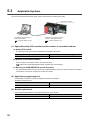
Applicable Systems . . . . . . . . . . . . . . . . . . . . . . . . . . . . . . . . . . . . . . . . . . . . . . . . . . . . . . . . . 58
CHAPTER 6 INSTALLATION AND WIRING
6.1
6.2
10
19
59
Installation. . . . . . . . . . . . . . . . . . . . . . . . . . . . . . . . . . . . . . . . . . . . . . . . . . . . . . . . . . . . . . . . . 59
Tests Before Wiring. . . . . . . . . . . . . . . . . . . . . . . . . . . . . . . . . . . . . . . . . . . . . . . . . . . . . . . . . . 60
6.2.1
Hardware test. . . . . . . . . . . . . . . . . . . . . . . . . . . . . . . . . . . . . . . . . . . . . . . . . . . . . . . . . . . . . 60
6.2.2
Self-loopback test. . . . . . . . . . . . . . . . . . . . . . . . . . . . . . . . . . . . . . . . . . . . . . . . . . . . . . . . . . 62
6.3
Wiring . . . . . . . . . . . . . . . . . . . . . . . . . . . . . . . . . . . . . . . . . . . . . . . . . . . . . . . . . . . . . . . . . . . . 64
6.4
Tests After Wiring . . . . . . . . . . . . . . . . . . . . . . . . . . . . . . . . . . . . . . . . . . . . . . . . . . . . . . . . . . . 67
6.4.1
Loop test . . . . . . . . . . . . . . . . . . . . . . . . . . . . . . . . . . . . . . . . . . . . . . . . . . . . . . . . . . . . . . . . 67
6.4.2
Cable test . . . . . . . . . . . . . . . . . . . . . . . . . . . . . . . . . . . . . . . . . . . . . . . . . . . . . . . . . . . . . . . . 74
6.4.3
Communication test . . . . . . . . . . . . . . . . . . . . . . . . . . . . . . . . . . . . . . . . . . . . . . . . . . . . . . . . 75
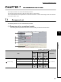
CHAPTER 7 PARAMETER SETTING
77
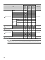
7.1
Parameter List . . . . . . . . . . . . . . . . . . . . . . . . . . . . . . . . . . . . . . . . . . . . . . . . . . . . . . . . . . . . . 77
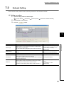
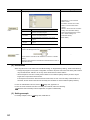
7.2
Network Setting . . . . . . . . . . . . . . . . . . . . . . . . . . . . . . . . . . . . . . . . . . . . . . . . . . . . . . . . . . . . 79
7.3
Network Configuration Setting . . . . . . . . . . . . . . . . . . . . . . . . . . . . . . . . . . . . . . . . . . . . . . . . . 81
7.4
Network Operation Setting . . . . . . . . . . . . . . . . . . . . . . . . . . . . . . . . . . . . . . . . . . . . . . . . . . . . 85
7.5
Refresh Parameters . . . . . . . . . . . . . . . . . . . . . . . . . . . . . . . . . . . . . . . . . . . . . . . . . . . . . . . . . 86
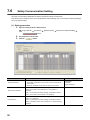
7.6
Safety Communication Setting . . . . . . . . . . . . . . . . . . . . . . . . . . . . . . . . . . . . . . . . . . . . . . . . . 90
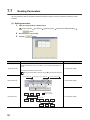
7.7
Routing Parameters . . . . . . . . . . . . . . . . . . . . . . . . . . . . . . . . . . . . . . . . . . . . . . . . . . . . . . . . . 92
CHAPTER 8 FUNCTIONS
8.1
8.2
8.3
96
Safety Communication Function. . . . . . . . . . . . . . . . . . . . . . . . . . . . . . . . . . . . . . . . . . . . . . . . 96
8.1.1
Communication with safety stations. . . . . . . . . . . . . . . . . . . . . . . . . . . . . . . . . . . . . . . . . . . . 96
8.1.2
Error log registration function . . . . . . . . . . . . . . . . . . . . . . . . . . . . . . . . . . . . . . . . . . . . . . . . . 99
8.1.3
Safety station interlock function . . . . . . . . . . . . . . . . . . . . . . . . . . . . . . . . . . . . . . . . . . . . . . 100
Cyclic Transmission . . . . . . . . . . . . . . . . . . . . . . . . . . . . . . . . . . . . . . . . . . . . . . . . . . . . . . . . 102
8.2.1
Data flow and link device assignment . . . . . . . . . . . . . . . . . . . . . . . . . . . . . . . . . . . . . . . . . 103
8.2.2
Link refresh . . . . . . . . . . . . . . . . . . . . . . . . . . . . . . . . . . . . . . . . . . . . . . . . . . . . . . . . . . . . . 104
8.2.3
Assurance of cyclic data integrity. . . . . . . . . . . . . . . . . . . . . . . . . . . . . . . . . . . . . . . . . . . . . 106
8.2.4
Scan synchronization specification . . . . . . . . . . . . . . . . . . . . . . . . . . . . . . . . . . . . . . . . . . . 112
8.2.5
Input status setting in case of failure. . . . . . . . . . . . . . . . . . . . . . . . . . . . . . . . . . . . . . . . . . 113
8.2.6
Output status setting for CPU module STOP . . . . . . . . . . . . . . . . . . . . . . . . . . . . . . . . . . . . 115
8.2.7
Cyclic transmission stop and restart . . . . . . . . . . . . . . . . . . . . . . . . . . . . . . . . . . . . . . . . . . 116
Transient Transmission. . . . . . . . . . . . . . . . . . . . . . . . . . . . . . . . . . . . . . . . . . . . . . . . . . . . . . 117
8.3.1
Communication within the same network. . . . . . . . . . . . . . . . . . . . . . . . . . . . . . . . . . . . . . . 117
8.3.2
Communication with different networks . . . . . . . . . . . . . . . . . . . . . . . . . . . . . . . . . . . . . . . . 118
8.4
Reserved station specification and reserved station function disable . . . . . . . . . . . . . . . . . . 119
8.5
Error Invalid Station and Temporary Error Invalid Station Setting Function . . . . . . . . . . . . . . 120
8.6
Loopback Function . . . . . . . . . . . . . . . . . . . . . . . . . . . . . . . . . . . . . . . . . . . . . . . . . . . . . . . . . 121
CHAPTER 9 CC-Link IE FIELD NETWORK DIAGNOSTICS
124
9.1
Diagnostic Items . . . . . . . . . . . . . . . . . . . . . . . . . . . . . . . . . . . . . . . . . . . . . . . . . . . . . . . . . . . 124
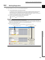
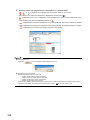
9.2
Starting Diagnostics . . . . . . . . . . . . . . . . . . . . . . . . . . . . . . . . . . . . . . . . . . . . . . . . . . . . . . . . 127
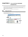
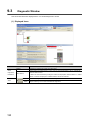
9.3
Diagnostic Window . . . . . . . . . . . . . . . . . . . . . . . . . . . . . . . . . . . . . . . . . . . . . . . . . . . . . . . . . 130
9.4
Link Start/Stop. . . . . . . . . . . . . . . . . . . . . . . . . . . . . . . . . . . . . . . . . . . . . . . . . . . . . . . . . . . . . 138
9.5
Network Event History . . . . . . . . . . . . . . . . . . . . . . . . . . . . . . . . . . . . . . . . . . . . . . . . . . . . . . 140
9.6
Canceling/Restoring Reserved Station Setting. . . . . . . . . . . . . . . . . . . . . . . . . . . . . . . . . . . . 142
9.7
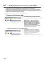
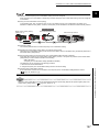
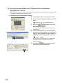
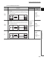
Setting/Canceling Temporary Error Invalid Station . . . . . . . . . . . . . . . . . . . . . . . . . . . . . . . . . 146
9.8
Remote Operation . . . . . . . . . . . . . . . . . . . . . . . . . . . . . . . . . . . . . . . . . . . . . . . . . . . . . . . . . 151
CHAPTER 10 DEDICATED INSTRUCTIONS
152
10.1
List of Dedicated Instructions . . . . . . . . . . . . . . . . . . . . . . . . . . . . . . . . . . . . . . . . . . . . . . . . . 152
10.2
Precautions for Dedicated Instructions . . . . . . . . . . . . . . . . . . . . . . . . . . . . . . . . . . . . . . . . . . 155
10.2.1 Precautions for link dedicated instructions. . . . . . . . . . . . . . . . . . . . . . . . . . . . . . . . . . . . . . 155
11
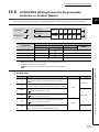
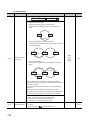
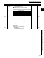
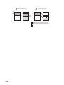
10.3
Understanding the Documentation on Dedicated Instructions . . . . . . . . . . . . . . . . . . . . . . . . 158
10.4
JP/GP.READ (Reading Data from the Programmable Controller on Another Station) . . . . . . 160
10.5
JP/GP.SREAD (Reading Data from the Programmable Controller on Another Station) . . . . . 168
10.6
JP/GP.WRITE (Writing Data to the Programmable Controller on Another Station) . . . . . . . . 175
10.7
JP/GP.SWRITE (Writing Data to the Programmable Controller on Another Station) . . . . . . . 187
10.8
JP/GP.REQ (Reading/Writing Clock Data) . . . . . . . . . . . . . . . . . . . . . . . . . . . . . . . . . . . . . . . 194
CHAPTER 11 PROGRAMMING
209
11.1
Precautions for Programming . . . . . . . . . . . . . . . . . . . . . . . . . . . . . . . . . . . . . . . . . . . . . . . . . 209
11.2
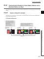
Communication Example of when Safety Stations and a Standard Station are Used . . . . . . 211
11.3
11.2.1
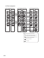
System configuration example . . . . . . . . . . . . . . . . . . . . . . . . . . . . . . . . . . . . . . . . . . . . . . . 211
11.2.2
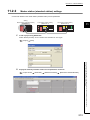
Master station (standard station) settings . . . . . . . . . . . . . . . . . . . . . . . . . . . . . . . . . . . . . . 213
11.2.3
Local station (safety station) settings . . . . . . . . . . . . . . . . . . . . . . . . . . . . . . . . . . . . . . . . . . 215
11.2.4
Checking the network status . . . . . . . . . . . . . . . . . . . . . . . . . . . . . . . . . . . . . . . . . . . . . . . . 218
11.2.5
Program example. . . . . . . . . . . . . . . . . . . . . . . . . . . . . . . . . . . . . . . . . . . . . . . . . . . . . . . . . 219
Using Link Special Relay (SB) and Link Special Register (SW) . . . . . . . . . . . . . . . . . . . . . . . 221
CHAPTER 12 TROUBLESHOOTING
235
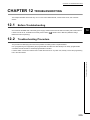
12.1
Before Troubleshooting . . . . . . . . . . . . . . . . . . . . . . . . . . . . . . . . . . . . . . . . . . . . . . . . . . . . . 235
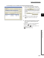
12.2
Troubleshooting Procedure . . . . . . . . . . . . . . . . . . . . . . . . . . . . . . . . . . . . . . . . . . . . . . . . . . 235
12.3
Checking the LEDs . . . . . . . . . . . . . . . . . . . . . . . . . . . . . . . . . . . . . . . . . . . . . . . . . . . . . . . . . 239
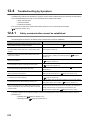
12.4
Troubleshooting by Symptom . . . . . . . . . . . . . . . . . . . . . . . . . . . . . . . . . . . . . . . . . . . . . . . . . 242
12.4.1 Safety communication cannot be established . . . . . . . . . . . . . . . . . . . . . . . . . . . . . . . . . . . 242
12.4.2 Cyclic transmission cannot be performed . . . . . . . . . . . . . . . . . . . . . . . . . . . . . . . . . . . . . . 243
12.4.3 Transient transmission cannot be performed . . . . . . . . . . . . . . . . . . . . . . . . . . . . . . . . . . . . 244
12.4.4 Station is disconnected from the network. . . . . . . . . . . . . . . . . . . . . . . . . . . . . . . . . . . . . . . 244
12.4.5 Station is repeatedly disconnected and reconnected . . . . . . . . . . . . . . . . . . . . . . . . . . . . . 245
12.4.6 Communication is unstable . . . . . . . . . . . . . . . . . . . . . . . . . . . . . . . . . . . . . . . . . . . . . . . . . 245
12.5
Error Code List . . . . . . . . . . . . . . . . . . . . . . . . . . . . . . . . . . . . . . . . . . . . . . . . . . . . . . . . . . . . 246
12.6
Checking the Master/Local Module Status by System Monitor. . . . . . . . . . . . . . . . . . . . . . . . 261
APPENDICES
264
Appendix 1 Details of I/O Signals. . . . . . . . . . . . . . . . . . . . . . . . . . . . . . . . . . . . . . . . . . . . . . . . . . . 264
Appendix 1.1
Module failure (X0) . . . . . . . . . . . . . . . . . . . . . . . . . . . . . . . . . . . . . . . . . . 264
Appendix 1.2
Own station data link status (X1) . . . . . . . . . . . . . . . . . . . . . . . . . . . . . . . . . 264
Appendix 1.3
Other stations data link status (X3) . . . . . . . . . . . . . . . . . . . . . . . . . . . . . . . 265
Appendix 1.4
Module ready (XF) . . . . . . . . . . . . . . . . . . . . . . . . . . . . . . . . . . . . . . . . . . 265
Appendix 2 Details of Buffer Memory Addresses. . . . . . . . . . . . . . . . . . . . . . . . . . . . . . . . . . . . . . . 266
Appendix 2.1
Link device area (buffer memory address: 0 to 18975 (0H to 4A1FH)) . . . . . . . . . 266
Appendix 2.2
RX offset/size information (buffer memory address: 19456 to 19695 (4C00H to 4CEFH))
. . . . . . . . . . . . . . . . . . . . . . . . . . . . . . . . . . . . . . . . . . . . . . . . . . . . . . . 269
Appendix 2.3
RY offset/size information (buffer memory address: 19712 to 19951 (4D00H to 4DEFH))
Appendix 2.4
RWw offset/size information (buffer memory address: 19968 to 20207 (4E00H to
. . . . . . . . . . . . . . . . . . . . . . . . . . . . . . . . . . . . . . . . . . . . . . . . . . . . . . . 269
4EEFH)) . . . . . . . . . . . . . . . . . . . . . . . . . . . . . . . . . . . . . . . . . . . . . . . . . 270
12
Appendix 2.5
RWr offset/size information (buffer memory address: 20224 to 20463 (4F00H to
4FEFH)) . . . . . . . . . . . . . . . . . . . . . . . . . . . . . . . . . . . . . . . . . . . . . . . . . 270
Appendix 2.6
Own station information (buffer memory address: 20512 to 20536 (5020H to 5038H))
. . . . . . . . . . . . . . . . . . . . . . . . . . . . . . . . . . . . . . . . . . . . . . . . . . . . . . . 271
Appendix 2.7
Other station information (buffer memory address: 20544 to 24383 (5040H to 5F3FH))
. . . . . . . . . . . . . . . . . . . . . . . . . . . . . . . . . . . . . . . . . . . . . . . . . . . . . . . 272
Appendix 3 Link Special Relay (SB) List . . . . . . . . . . . . . . . . . . . . . . . . . . . . . . . . . . . . . . . . . . . . . 273
Appendix 4 Link Special Register (SW) List. . . . . . . . . . . . . . . . . . . . . . . . . . . . . . . . . . . . . . . . . . . 286
Appendix 5 Processing Time . . . . . . . . . . . . . . . . . . . . . . . . . . . . . . . . . . . . . . . . . . . . . . . . . . . . . . 302
Appendix 5.1
Link refresh time . . . . . . . . . . . . . . . . . . . . . . . . . . . . . . . . . . . . . . . . . . . 302
Appendix 5.2
Link scan time . . . . . . . . . . . . . . . . . . . . . . . . . . . . . . . . . . . . . . . . . . . . . 303
Appendix 5.3
Cyclic transmission delay time . . . . . . . . . . . . . . . . . . . . . . . . . . . . . . . . . . 304
Appendix 5.4
Transmission interval monitoring time . . . . . . . . . . . . . . . . . . . . . . . . . . . . . 308
Appendix 5.5
Safety refresh monitoring time . . . . . . . . . . . . . . . . . . . . . . . . . . . . . . . . . . 309
Appendix 5.6
Transmission delay time of dedicated instructions . . . . . . . . . . . . . . . . . . . . . 310
Appendix 6 New and Improved Functions . . . . . . . . . . . . . . . . . . . . . . . . . . . . . . . . . . . . . . . . . . . . 312
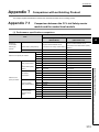
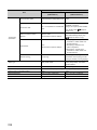
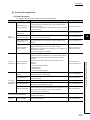
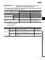
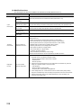
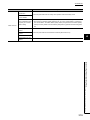
Appendix 7 Comparison with an Existing Product . . . . . . . . . . . . . . . . . . . . . . . . . . . . . . . . . . . . . . 313
Appendix 7.1
Comparison between the CC-Link Safety master module and the master/local
module. . . . . . . . . . . . . . . . . . . . . . . . . . . . . . . . . . . . . . . . . . . . . . . . . . 313
Appendix 7.2
Comparison between the Q series master/local module and the master/local module
. . . . . . . . . . . . . . . . . . . . . . . . . . . . . . . . . . . . . . . . . . . . . . . . . . . . . . . 317
Appendix 8 Precautions for When Connecting the MELSEC iQ-R Series Module . . . . . . . . . . . . . 320
Appendix 9 Checking the Serial Number and Function Version . . . . . . . . . . . . . . . . . . . . . . . . . . . 321
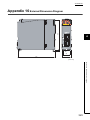
Appendix 10 External Dimension Diagram . . . . . . . . . . . . . . . . . . . . . . . . . . . . . . . . . . . . . . . . . . . . 323
INDEX
325
REVISIONS . . . . . . . . . . . . . . . . . . . . . . . . . . . . . . . . . . . . . . . . . . . . . . . . . . . . . . . . . . . . . . . . . . . . . . 328
WARRANTY . . . . . . . . . . . . . . . . . . . . . . . . . . . . . . . . . . . . . . . . . . . . . . . . . . . . . . . . . . . . . . . . . . . . . 329
13
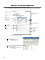
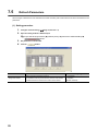
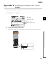
MANUAL PAGE ORGANIZATION
In this manual, pages are organized and the symbols are used as shown below.
The following illustration is for explanation purpose only, and should not be referred to as an actual documentation.
"" is used for
window names and items.
The chapter of
the current page is shown.
shows operating
procedures.
shows mouse
operations.*1
[ ] is used for items
in the menu bar and
the project window.
The section of
the current page is shown.
Ex. shows setting or
operating examples.
shows reference
manuals.
shows notes that
require attention.
shows
reference pages.
shows useful
information.
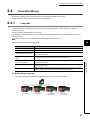
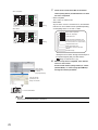
*1
The mouse operation example is provided below.
Menu bar
Ex.
[Online]
[Write to PLC...]
Select [Online] on the menu bar,
and then select [Write to PLC...].
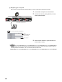
Project data list
Ex.
Project data list
[Parameter]
[PLC parameter]
In the Project data list, expand [Parameter] and
select [PLC parameter].
14
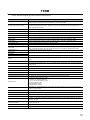
TERM
Unless otherwise specified, this manual uses the following terms.
Term
Description
Safety programmable controller
A generic term for a safety CPU module, a safety power supply module, a safety main base unit, a CC-Link Safety
master module, CC-Link Safety remote I/O modules, and a master/local module
Standard programmable controller
A generic term for MELSEC-Q series, MELSEC-L series, MELSEC-QnA series, MELSEC-A series, and MELSECFX series modules (This term is used to distinguish a programmable controller that uses these modules from a
safety programmable controller.)
QSCPU
Another term for the MELSEC-QS series CPU module
LCPU
Another term for the MELSEC-L series CPU module
QCPU
Another term for the MELSEC-Q series CPU module
QnACPU
Another term for the MELSEC-QnA series CPU module
ACPU
Another term for the MELSEC-A series CPU module
System A CPU
A CPU module where the system A connector of a tracking cable is connected in a redundant system
System B CPU
A CPU module where the system B connector of a tracking cable is connected in a redundant system
Control system CPU
A CPU module that controls operations in a redundant system
Standby system CPU
A CPU module that stands by in case the control system fails in a redundant system
Control CPU
A CPU module that controls connected I/O modules and intelligent function modules. In a multiple CPU system,
there are multiple CPU modules and each connected module can be controlled by a different CPU module.
Programming tool
A generic term for GX Works2 and GX Developer
GX Developer
GX Works2
The product name of the software package for the MELSEC programmable controllers
CC-Link IE Field Network
A high-speed and large-capacity open field network that is based on Ethernet (1000BASE-T)
CC-Link
A field network system where data processing for control and information can be simultaneously performed at high
speed
Safety CPU module
The abbreviation for the QS001CPU safety CPU module
Master/local module
The abbreviation for the QS0J71GF11-T2 CC-Link IE Field Network master/local module. This module supports
safety functions.
Q series master/local module
The abbreviation for the QJ71GF11-T2 CC-Link IE Field Network master/local module
L series master/local module
The abbreviation for the LJ71GF11-T2 CC-Link IE Field Network master/local module
CC-Link Safety master module
The abbreviation for the QS0J61BT12 CC-Link Safety system master module
Head module
The abbreviation for the LJ72GF15-T2 CC-Link IE Field Network head module
Ethernet adapter module
The abbreviation for the NZ2GF-ETB CC-Link IE Field Network Ethernet adapter module
CC-Link IE Field Network interface board
The abbreviation for the Q81BD-J71GF11-T2 CC-Link IE Field Network interface board
Network module
A generic term for the following modules:
• Module on CC-Link IE Field Network
• CC-Link IE Controller Network module
• Ethernet interface module
• MELSECNET/H module
• MELSECNET/10 module
Intelligent function module
A MELSEC-Q/L series module that has functions other than input and output, such as an A/D converter module
and D/A converter module
Safety data
Data exchanged through safety communication
Safety connection
A connection established for safety communication
Safety communication
A function to exchange safety data between safety stations on the same network
Standard communication
A generic term for cyclic transmission and transient transmission
Cyclic transmission
A function by which data are periodically exchanged among stations on the same network using link devices (RX,
RY, RWw, and RWr)
Transient transmission
A function of communication with another station, which is used when requested by a dedicated instruction
or a programming tool
Safety station
A generic term for a station that performs safety communication and standard communication
Standard station
A generic term for a station that performs standard communication
15
Term
Description
Master station
A station that controls the entire network. Only one master station can be used in a network.
This station serves as a safety station or a standard station, and can perform cyclic transmission and transient
transmission with all stations.
When set as a safety station, the station can perform safety communication with another safety station on the
same network.
Local station
A station that serves as a safety station or a standard station. This station can perform cyclic transmission and
transient transmission with the master station and other local stations.
When set as a safety station, the station can perform safety communication with another safety station on the
same network. The station is controlled by programs in the CPU module or other equivalent modules on the
station.
Remote I/O station
A station that exchanges I/O signals (bit data) with the master station by cyclic transmission
Remote device station
A station that exchanges I/O signals (bit data) and I/O data (word data) with another station by cyclic transmission.
This station responds to a transient transmission request from another station.
Intelligent device station
A station that exchanges I/O signals (bit data) and I/O data (word data) with another station by cyclic transmission.
This station responds to a transient transmission request from another station and also issues a transient
transmission request to another station.
Slave station
A generic term for a local station, remote I/O station, remote device station, and intelligent device station
Reserved station
A station reserved for future use. This station is not actually connected, but counted as a connected station.
Relay station
A station that includes two or more network modules. Data are passed through this station to stations on other
networks.
Data link
Generic term for cyclic transmission and transient transmission
Seamless communication
Communication that allows users to access a different kind of networks without having to consider the differences
as if data were exchanged within one single network.
Routing
A process of selecting paths for communication with other networks.
CC-Link IE Field Network requires communication paths to be preset using routing parameters to communicate
with stations on different networks.
Dedicated instruction
An instruction that simplifies programming for using functions of intelligent function modules
Link dedicated instruction
A dedicated instruction used for transient transmission with a programmable controller on another station.
This instruction allows a master/local module to communicate with programmable controllers on the same network
(CC-Link IE Field Network) and on other networks (Ethernet, CC-Link IE Controller Network, and MELSECNET/H).
Return
Processing that restarts data link when a station recovers from an error
Disconnection
Processing that stops data link if a data link error occurs
Loopback
A function that disconnects the station in which an error has occurred, and continues data link with the stations that
are operating normally. Stations connected after the faulty station can also continue data link.
Device
A device (X, Y, M, D, or others) in a CPU module
Link device
A device (RX, RY, RWr, or RWw) in a module on CC-Link IE Field Network
Remote input (RX)
Bit data input from a slave station to the master station (For some areas in a local station, data are input in the
opposite direction.)
Page 103, Section 8.2.1
Remote output (RY)
Bit data output from the master station to a slave station (For some areas in a local station, data are output in the
opposite direction.)
Remote register (RWr)
Word data input from a slave station to the master station (For some areas in a local station, data are input in the
opposite direction.)
Remote register (RWw)
Word data output from the master station to a slave station (For some areas in a local station, data are output in the
opposite direction.)
Page 103, Section 8.2.1
Page 103, Section 8.2.1
Page 103, Section 8.2.1
Link special relay (SB)
Bit data that indicates the operating status and data link status of a module on CC-Link IE Field Network
Link special register (SW)
Word data that indicates the operating status and data link status of a module on CC-Link IE Field Network
Link scan (Link scan time)
Time required for all the stations on the network to transmit data. The link scan time depends on data volume and
the number of transient transmission requests.
Link refresh
Data transfer between a link device in a module on CC-Link IE Field Network and a device in a CPU module. Link
refresh is performed in the END processing of the CPU module's sequence scan.
Baton pass
A token to send data over a network
Buffer memory
A memory in an intelligent function module, where data (such as setting values and monitoring values) exchanged
with a CPU module are stored
16
Term
Description
Buffer memory address
An address that indicates the storage location of data assigned to the buffer memory in an intelligent function
module
RAS
The abbreviation for Reliability, Availability, and Serviceability. This term refers to usability of automated
equipment.
READ
The abbreviation for JP.READ and GP.READ
SREAD
The abbreviation for JP.SREAD and GP.SREAD
WRITE
The abbreviation for JP.WRITE and GP.WRITE
SWRITE
The abbreviation for JP.SWRITE and GP.SWRITE
REQ
The abbreviation for JP.REQ and GP.REQ
17
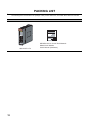
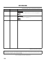
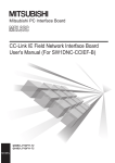
PACKING LIST
The following items are included in the package of this product. Before use, check that all the items are included.
QS0J71GF11-T2
QS0J71GF11-T2
18
MELSEC-QS CC-Link IE Field Network
Master/Local Module
User's Manual (Hardware)
CHAPTER 1 CC-Link IE FIELD NETWORK
CHAPTER 1
1.1
CC-Link IE FIELD NETWORK
1
CC-Link IE Field Network
CC-Link IE Field Network is a high-speed and large-capacity open field network that is based on Ethernet
(1000BASE-T).
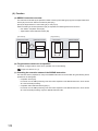
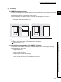
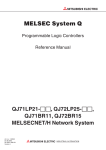
(1) Data communication
High-speed and large-capacity data communication is available between a master station and slave stations on
CC-Link IE Field Network. A safety station can operate safety communication and standard communication
simultaneously.
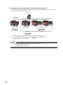
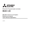
(a) Safety communication
Data communication ensuring high safety (safety communication) can be performed.
Data is communicated after a safety connection is established between safety stations on the same network.
(
Page 96, Section 8.1)
Master station
(safety station)
Local station
(safety station)
1) Safety connection
establishment
Master
station
(safety station)
Local
station
(safety station)
1.1 CC-Link IE Field Network
Safety CPU
module
Device
Safety CPU
module
Device
2) Safety data transfer
After safety connection
is established, data
is communicated.
Device
Device
3) Safety data transfer
19
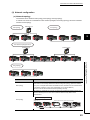
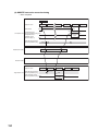
(b) Standard communication
• Periodic communication (cyclic transmission)
Data is periodically communicated among stations within the same network. (
Master station
(standard station)
CPU module
Intelligent
device station
Master
station
(standard station)
Intelligent
device station
Page 102, Section 8.2)
Local station
(safety station)
Local station
(safety station)
Intelligent
device station
Intelligent
device station
Local station
Safety
CPU module
Local station
(safety station)
(safety station)
Safety
CPU module
X
RX
RX
RX
RY
Y
RY
Y
Y
RY
RY
RY
RX
X
RX
X
RWw
RWw
RWw
RWr
RWr
RWr
RWr
RWw
W
RWr
W
RWw
• Non-periodic communication (transient transmission)
Data is communicated upon request. (
Safety
CPU module
Command
Master station
(safety station)
Page 117, Section 8.3)
Read
request
Local station
(safety station)
Safety
CPU module
Instruction
Device
1234H
20
Response
data
Device
1234H
W
CHAPTER 1 CC-Link IE FIELD NETWORK
1
(2) 1Gbps communication speed
1Gbps communication speed allows high-speed communication. Also, the takt time can be reduced due to the
improved performance of communication response.
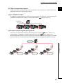
(3) Use of Ethernet cable
A 1000BASE-T-compliant Ethernet is used for the connection interface. The wiring cost can be reduced because
1000BASE-T-compliant Ethernet cables are commercially available. (
Page 56, Section 5.2)
1000BASE-T
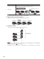
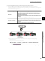
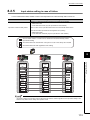
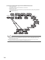
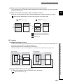
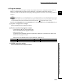
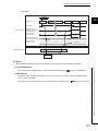
(4) Flexible wiring for system arrangements
The network can be wired into star topology, line topology, and ring topology. (
For star topology, a 1000BASE-T compliant switching hub can be used. (
Page 47, Section 5.1.1)
Page 57, Section 5.2.2)
Wiring is highly flexible because a network can consist of a combination of star and line topologies. For example,
the control panels can be connected through a star topology and the production lines through a line topology.
Star topology
Line topology
1.1 CC-Link IE Field Network
Line topology
Line topology
21
1.2
Master/Local Modules
A master/local module is used to connect a safety programmable controller to CC-Link IE Field Network.
The module is used being mounted on a safety base unit.
The module can be used as the following stations on CC-Link IE Field Network.
• Master station (safety station)
• Local station (safety station)
• Local station (standard station)
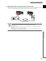
(1) Communication that ensures safety (safety communication)
Data communication ensuring high safety (safety communication) can be performed.
Data is communicated after a safety connection is established between safety stations on the same network.
(
Page 96, Section 8.1)
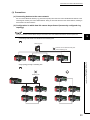
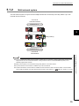
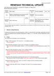
(a) Safety stations added on CC-Link IE Field Network
Safety programmable controllers and standard programmable controllers can co-exist on the same network. A
network system with high safety can be easily established by adding safety stations on an existing CC-Link IE
Field Network. (
Page 47, Section 5.1.1)
Adding a
station
Safety communication
Adding a
station
Safety
station
Standard
station
Standard
station
Safety
station
The master/local module has acquired certification of the highest safety level (SIL3 of IEC 61508, Category 4 of EN 654-1,
and Category 4 performance level "e" of EN ISO 13849-1) applicable to programmable controllers.
22
CHAPTER 1 CC-Link IE FIELD NETWORK
1
(2) High-speed periodic communication (cyclic transmission)
Since transmission delay time is short, delay caused by the network does not need to be considered (if the link
scan time of each master/local module is shorter than the scan time of the safety CPU module).
Command
High speed
Master/local modules can perform cyclic transmissions in combination with the following functions:
(
Page 35, Section 3.3)
• Auto transfer of data between the link devices in the master/local module and the devices in the safety CPU
module
• Cyclic data assurance in units of 32 bits or per station
• Status setting (hold or clear) of input data of standard communication to which a data link error has occurred
• Station reservation for future connection, and others
1.2 Master/Local Modules
23
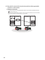
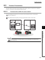
(3) Non-periodic communication (transient transmission) with programmable
controllers on other stations
(a) Reading or writing data
A master/local module can access programmable controllers on other stations by dedicated instructions.
(
Page 152, Section 10.1)
Seamless access of programmable controllers on other networks such as Ethernet, CC-Link IE Controller
Network, MELSECNET/H, and MELSECNET/10 is also possible.
Safety CPU module
Command
Master station
(safety station)
Local station
(safety station)
Safety CPU module
READ
24
Device
Device
1234H
1234H
CHAPTER 1 CC-Link IE FIELD NETWORK
1
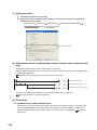
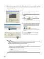
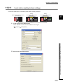
(4) Settings and diagnostics by GX Developer
(a) Setting parameters
Parameters for master/local modules can be set using GX Developer. (
Page 77, CHAPTER 7)
1.2 Master/Local Modules
25
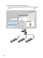
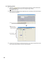
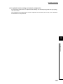
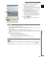
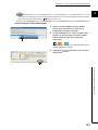
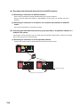
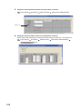
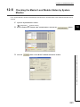
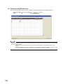
(b) Checking CC-Link IE Field Network status graphically
CC-Link IE Field Network status can be checked using GX Developer. Error locations, error causes, and event
history are displayed on the window. This allows the system to quickly recover from errors. (
CHAPTER 9)
Displays error details
Displays the status of
CC-Link IE Field Network
Displays the network event history
26
Page 124,
CHAPTER 1 CC-Link IE FIELD NETWORK
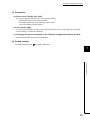
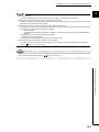
(c) Seamless access to other networks
GX Developer can seamlessly access (test or monitor) systems composed of CC-Link IE Field Network and
1
other networks. The accessible networks are Ethernet, CC-Link IE Controller Network, MELSECNET/H,
MELSECNET/10, and CC-Link.
Seamless access enables the user to change the access target without modifying the connection between the
personal computer and programmable controller.
For details on access range, refer to the following.
QSCPU User’s Manual (Function Explanation, Program Fundamentals)
Systems on other networks
can be tested or monitored.
CC-Link IE Controller Network
Network No. 1
GX Developer
1.2 Master/Local Modules
(Relay station)
Seamless
access
CC-Link IE Field Network
Network No. 2
27
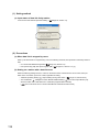
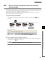
(5) Replacing CC-Link IE Field Network devices without stopping the system
For star topology, slave stations can be replaced without powering off the whole system.
Star topology
Replacement
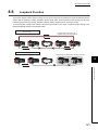
(6) RAS function when a communication error occurs
(a) During safety communication
When a communication error occurs between safety stations, communication is automatically disconnected in
order to prevent incorrect input/output from/to the faulty station. (
Page 100, Section 8.1.3)
Safety
communication
Master station
(safety station)
Station No. 0
Error
Local station
(safety station)
Station No. 3
Local station
(standard station)
Station No. 2
Local station
(standard station)
Station No. 1
Local station
(standard station)
Station No. 2
Local station
(standard station)
Station No. 1
Communication
disconnection
and interlock
Master station
(safety station)
Station No. 0
28
Local station
(safety station)
Station No. 3
CHAPTER 1 CC-Link IE FIELD NETWORK
(b) During standard communication
1
When a communication error occurs, communication is automatically disconnected in order to prevent
incorrect input/output from/to the faulty station. When the disconnected station gets back to normal operation, it
automatically returns to the network and resumes data link. (
Page 35, Section 3.3.1)
Standard
communication
Master station
(safety station)
Station No. 0
Local station
(safety station)
Station No. 3
Local station
(standard station)
Station No. 2
Error
Local station
(standard station)
Station No. 1
Communication is
automatically
disconnected.
Master station
(safety station)
Station No. 0
Local station
(safety station)
Station No. 3
Local station
(standard station)
Station No. 2
Disconnection
Local station
(standard station)
Station No. 1
1.2 Master/Local Modules
When
recovered
from fault
Standard
communication
Master station
(safety station)
Station No. 0
Local station
(safety station)
Station No. 3
Local station
(standard station)
Station No. 2
Reconnection
Local station
(standard station)
Station No. 1
29
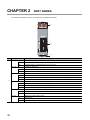
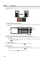
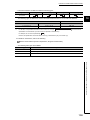
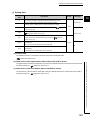
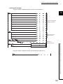
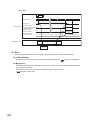
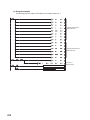
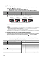
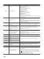
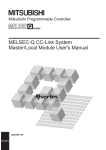
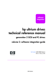
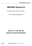
CHAPTER 2
PART NAMES
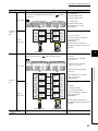
This chapter describes the names of each part of the master/local modules.
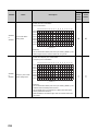
1)
2)
3)
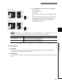
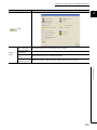
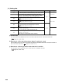
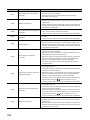
No.
Name
RUN LED
Indicates the operating status.
ON
Operates normally.
OFF
A hardware failure or a watchdog timer error has occurred.
MST LED
Indicates the station type.
ON
Operates as a master station (safety station).
OFF
Operates as a local station.
MODE LED
1)
Indicates the mode.
ON
In online mode.
Flashing
In test mode (The module is performing a hardware test, self-loopback test, or loop test.)
OFF
D LINK LED
In offline mode. (Data link not performed)
Indicates the status of the data link.
ON
Data link in operation (cyclic transmission in progress)
Flashing
Data link in operation (cyclic transmission stopped)
OFF
Data link not performed (disconnected)
SD LED
Displays the sending status of data.
ON
Sending data.
OFF
Data not sent.
ON
Receiving data.
OFF
Data not received.
RD LED
30
Application
Displays the reception status of data.
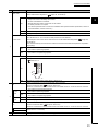
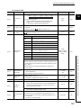
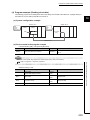
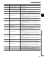
CHAPTER 2 PART NAMES
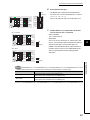
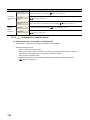
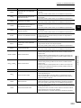
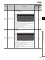
No.
Name
Application
Indicates the error status of the master/local module. The description of the errors can be confirmed in CC-
ERR. LED
Link IE Field Network diagnostics. (
Page 124, CHAPTER 9)
One of the following errors has occurred:
2
• A stop error occurs in the safety CPU module.
• An error was detected in all stations.
ON
• Modules with same station number exist on the network.
• A network parameter is corrupted.
• The network parameter does not match the installation status. (Reserved station specification, number of
connected stations, network number etc.)
Flashing
A data link faulty station was detected.
OFF
Working normally.
Indicates the error status of the received data and the circuit. When the L ERR. LED is on, you can check
the L ER LED for "P1" or "P2" to see on which port the error was detected.
The description of the errors can be confirmed in CC-Link IE Field Network diagnostics. (
L ERR. LED
Page 124,
CHAPTER 9)
This LED automatically turns off when the module has received normal data and loopback is completed in
ring topology.
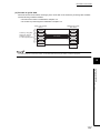
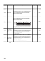
1)
ON
OFF
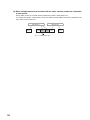
ST.NO.
• The module has received abnormal data.
• The module is performing loopback.
• The module has received normal data.
• The module is not performing loopback.
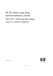
Displays the station number of the master/local module.
Displays the station number.
Ex. Station No. 15
1
ON
1
4
100
10
1
10 + 5 = 15
OFF
Operates as a master station (safety station). (station No. 0)
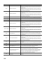
PORT1 connector for CC-Link IE Field Network (RJ45 connector)
P1
Connect an Ethernet cable. (
Page 64, Section 6.3)
There are no restrictions on the connection order of the cables for the "P1" connector and "P2" connector.
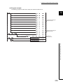
L ER
LED
2)
ON
OFF
• The module has received abnormal data.
• The module is performing loopback.
• The module has received normal data.
• The module is not performing loopback.
LINK
ON
Linkup in progress.
LED
OFF
Linkdown in progress.
PORT2 connector for CC-Link IE Field Network (RJ45 connector)
P2
Connect an Ethernet cable. (
Page 64, Section 6.3)
There are no restrictions on the connection order of the cables for the "P1" connector and "P2" connector.
L ER LED
LINK LED
3)
Serial number display
(Same as the "P1" connector)
Displays the serial number printed on the rating plate.
31
Remark
For LED indication when the master/local module is in test mode (when the module performs hardware test, self-loopback
test, or loop test), refer to the following.
● Hardware test:
Page 60, Section 6.2.1
● Self-loopback test:
● Loop test:
32
Page 62, Section 6.2.2
Page 67, Section 6.4.1
CHAPTER 3 SPECIFICATIONS
CHAPTER 3
SPECIFICATIONS
This chapter describes the specifications, function list, I/O signal, and buffer memory of the master/local module.
3.1
General Specifications
3
For the general specifications of the master/local module, refer to the following.
QSCPU User's Manual (Hardware Design and Maintenance and Inspection)
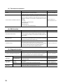
3.2
Performance Specifications
Item
Specifications
Master station (safety
1 station
Number of connectable
station)
(Up to 120 slave stations can be connected to the master station (safety station).)
stations per network
Local station (standard
station)
120 stations
Number of connectable safety stations per network
32 stations
Maximum number of networks
239
Maximum number of
Asynchronous mode
31 connections
Synchronous mode
8 connections
safety connections per
station
Input
8 words
connection
Output
8 words
RX
16384 points, 2KB
RY
16384 points, 2KB
RWr
8192 points, 16KB
RWw
8192 points, 16KB
RX
16384 points, 2KB
Maximum link points per network
Master station
RY
16384 points, 2KB
(safety station)
RWr
8192 points, 16KB
Maximum link points per
RWw
8192 points, 16KB
station
RX
2048 points, 256 bytes
RY
2048 points, 256 bytes
RWr
1024 points, 2048 bytes*2
RWw
1024 points, 2048 bytes*2
Local station*1
3.1 General Specifications
Number of safety inputs/outputs per safety
33
Item
Communication speed
Network topology
Connection cable
Ethernet
Specifications
1Gbps
Line topology, star topology (Coexistence of line topology and star topology is
possible.), and ring topology
An Ethernet cable that meets the 1000BASE-T standard: Category 5e or higher
(double shielded, STP), straight cable (
Page 56, Section 5.2.1)
Maximum station-to-station
100m max. (Compliant with ANSI/TIA/EIA-568-B (Category 5e))
distance
(
Page 66, Section 6.3 (2))
• Line topology: 12000m
(when cables are connected to 1 master station and 120 slave stations)
Overall cable distance
• Star topology: Depends on the system configuration.
• Ring topology: 12100m
(when cables are connected to 1 master station and 120 slave stations)
Number of cascade
connections
Up to 20
Communication method
Token passing method
Number of occupied I/O points
32 points (I/O assignment: Intelligent 32 points)
Internal current consumption (5VDC)
0.85A
External dimensions
98(H) × 27.4(W) × 115(D) [mm]
Weight
0.18kg
34
*1
The maximum number of points for one master station is listed. A local station can receive data from other stations in
*2
addition to this number of points. (
Page 96, Section 8.1.1)
256 points and 512 bytes when "Online (High Speed Mode)" is set
CHAPTER 3 SPECIFICATIONS
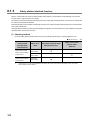
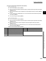
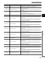
3.3
Function List
3.3.1
Using the master/local module as a master station (safety
station)
3
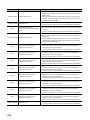
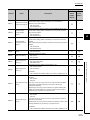
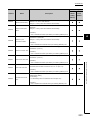
(1) Safety communication function
Function
Communication with safety stations
Description
Communication starts among safety stations on the same network
after safety connections are established.
Reference
Page 96, Section 8.1.1
Information on errors occurred in safety stations and errors
Error log registration function
occurred in communications among safety stations are transferred
Page 99, Section 8.1.2
to the safety CPU module and registered as error logs.
If an error occurs in safety communication, this function cuts off the
Safety station interlock function
safety communication and prevents automatic resumption of the
Page 100, Section 8.1.3
communication.
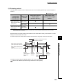
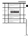
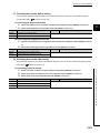
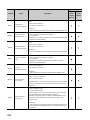
(2) Cyclic transmission
Function
Communication
with other
stations
Device and link
Reference
The master station (safety station) communicates I/O data in units
RX and RY
of bits with other stations.
Page 81, Section 7.3
Communication by
The master station (safety station) communicates I/O data in units
Page 103, Section 8.2.1
RWr and RWw
of words with other stations.
Link refresh
Transfer between the link device of the master/local module and the
Page 86, Section 7.5
device of the safety CPU module is performed automatically.
Page 104, Section 8.2.2
This mode is selected for optimizing the performance of cyclic
transmission based on the cyclic transmission and transient
Mode selection for cyclic transmission
transmission frequency.
Page 79, Section 7.2 (1)
The mode can be selected from "Online (Normal mode)" and
"Online (High-speed mode)".
Assurance of cyclic data integrity
Scan synchronization specification
The cyclic data integrity is assured in units of 32 bits or stationbased units.
Link scan is set to asynchronous or synchronous with the sequence
scan of the safety CPU module.
Input status setting for data link faulty
Select whether the input data from another station where the data
station
link error occurred is cleared or held.
Page 106, Section 8.2.3
Page 112, Section 8.2.4
Page 113, Section 8.2.5
When the safety CPU module mounted with a master/local module
Output status setting for CPU STOP
is set to STOP, whether cyclic data output is held or cleared can be
Page 115, Section 8.2.6
selected.
During debugging and other operations, cyclic transmission is
stopped. (Data reception from the slave station and data
Cyclic transmission stop and restart
transmission from own stations are stopped.) Also, the stopped
cyclic transmission is restarted.
Page 116, Section 8.2.7
Page 138, Section 9.4
Transient transmission is not stopped.
35
3.3 Function List
3.3.1 Using the master/local module as a master station (safety station)
device access
Description
Communication by
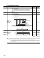
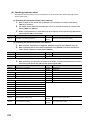
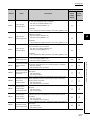
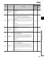
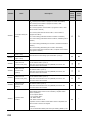
(3) Transient transmission
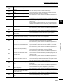
Function
Description
Communication within the same
Transient transmission is performed to other stations using
network
dedicated instructions and GX Developer.
Reference
Page 152, CHAPTER 10
By setting the routing parameters (communication path) using GX
Developer in advance, transient transmission can be performed to
stations on different networks through dedicated instructions or GX
Developer. Seamless communication is available with the following
Communication with different networks
networks.
Page 92, Section 7.7
• Ethernet
Page 118, Section 8.3.2
• CC-Link IE Controller Network
• MELSECNET/H
• MELSECNET/10
• CC-Link (when using GX Developer)
(4) RAS function
Function
Description
Reference
Only the slave station where an error occurs is disconnected, and
Slave station disconnection
data link continues with the stations that are operating normally.
In a line topology, all stations connected after the faulty station are
disconnected.
When the station disconnected from the network due to a data link
Automatic return
failure recovers, it automatically returns to the network and restarts
data link (for standard communication only).
Only the station where an error occurs is disconnected, and data
link continues with the stations that are operating normally.
Loopback function
All stations after the faulty station are disconnected in line topology.
Page 121, Section 8.6
By using the loopback function with ring topology, data link
continues with the stations that are operating normally.
(5) Diagnostic function
Function
Description
Reference
The status of CC-Link IE Field Network can be checked by GX
CC-Link IE Field Network diagnostics
Developer. The faulty area, cause of the fault and its corrective
Page 124, CHAPTER 9
action, and event history can be checked in GX Developer.
Individual unit
Hardware test
diagnostics
Self-loopback test
Own network
Loop test
diagnostics
Other network
diagnostics
36
Cable test
Communication test
Check the internal hardware of the master/local module.
Check the communication circuit of the transmission system of the
master/local module.
Check the network circuit status and parameter setting status of
each station.
Check the connection status of the Ethernet cable.
Check whether the communication path for transient transmission
from the own station to the target station is correct.
Page 60, Section 6.2.1
Page 62, Section 6.2.2
Page 67, Section 6.4.1
Page 74, Section 6.4.2
Page 75, Section 6.4.3
CHAPTER 3 SPECIFICATIONS
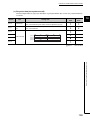
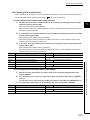
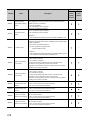
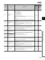
(6) Other functions
Function
Description
Reference
The reserved stations are included in the number of stations that
Reserved station specification
will be connected to the network in the future without actually
connecting them. Reserved stations are not detected as faulty
Page 119, Section 8.4
stations even though they are not actually connected.
Page 142, Section 9.6
Temporary cancel of the reserved
Reserved station specification can be temporarily cancelled without
station setting
changing the parameters.
3
Prevent the master station from detecting a slave station as a faulty
Error invalid station and temporary error
station even if the slave station is disconnected during data link.
Page 120, Section 8.5
invalid station setting
This can be used when replacing a slave station during data link, for
Page 146, Section 9.7
instance.
3.3 Function List
3.3.1 Using the master/local module as a master station (safety station)
37
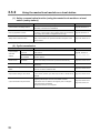
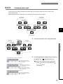
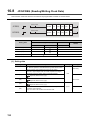
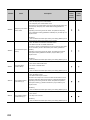
3.3.2
Using the master/local module as a local station
(1) Safety communication function (using the master/local module as a local
station (safety station))
Function
Communication with safety stations
Description
Communication starts among safety stations on the same network
after safety connections are established.
Reference
Page 96, Section 8.1.1
Information on errors occurred in safety stations and errors
Error log registration function
occurred in communications among safety stations are transferred
Page 99, Section 8.1.2
to the safety CPU module and registered as error logs.
If an error occurs in safety communication, this function cuts off the
Safety station interlock function
safety communication and prevents automatic resumption of the
Page 100, Section 8.1.3
communication.
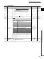
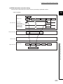
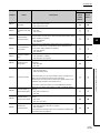
(2) Cyclic transmission
Function
Communication
with other
stations
Device and link
device access
Description
Reference
Communication by
I/O data in bit units is communicated between the local station and
RX and RY
other stations.
Page 81, Section 7.3
Communication by
I/O data in word units is communicated between the local station
Page 103, Section 8.2.1
RWr and RWw
and other stations.
Link refresh
Assurance of cyclic data integrity
Transfer between the link device of the master/local module and the
Page 86, Section 7.5
device of the safety CPU module is performed automatically.
Page 104, Section 8.2.2
The cyclic data integrity is assured in units of 32 bits or stationbased units.
Input status setting for data link faulty
Select whether the input data from another station where the data
station
link error occurred is cleared or held.
Page 106, Section 8.2.3
Page 113, Section 8.2.5
When the safety CPU module mounted with a master/local module
Output status setting for CPU STOP
is set to STOP, whether cyclic data output is held or cleared can be
Page 115, Section 8.2.6
selected.
During debugging and other operations, cyclic transmission is
stopped. (Data reception from the slave station and data
Cyclic transmission stop and restart
transmission from own stations are stopped.) Also, the stopped
cyclic transmission is restarted.
Transient transmission is not stopped.
38
Page 116, Section 8.2.7
Page 138, Section 9.4
CHAPTER 3 SPECIFICATIONS
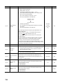
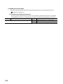
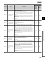
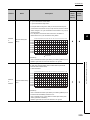
(3) Transient transmission
Function
Communication within the same network
Description
Transient transmission is performed to other stations using
dedicated instructions and GX Developer.
Reference
Page 152, CHAPTER 10
By setting the routing parameters (communication path) using GX
Developer in advance, transient transmission can be performed to
3
stations on different networks through dedicated instructions or GX
Developer. Seamless communication is available with the following
Communication with different networks
networks.
Page 92, Section 7.7
• Ethernet
Page 118, Section 8.3.2
• CC-Link IE Controller Network
• MELSECNET/H
• MELSECNET/10
• CC-Link (when using GX Developer)
(4) Diagnostic function
Function
Description
Reference
The status of CC-Link IE Field Network can be checked by GX
CC-Link IE Field Network diagnostics
Developer. The faulty area, cause of the fault and its corrective
Page 124, CHAPTER 9
action, and event history can be checked in GX Developer.
Individual unit
Hardware test
diagnostics
Self-loopback test
Own network
Loop test
diagnostics
diagnostics
Communication test
Check the communication circuit of the transmission system of the
master/local module.
Check the network circuit status and parameter setting status of
each station.
Check the connection status of the Ethernet cable.
Check whether the communication path for transient transmission
from the own station to the target station is correct.
Page 60, Section 6.2.1
Page 62, Section 6.2.2
Page 67, Section 6.4.1
Page 74, Section 6.4.2
Page 75, Section 6.4.3
39
3.3 Function List
3.3.2 Using the master/local module as a local station
Other network
Cable test
Check the internal hardware of the master/local module.
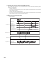
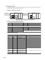
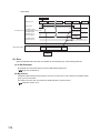
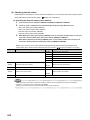
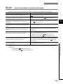
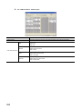
3.4
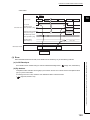
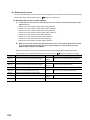
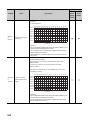
List of I/O Signals
This section lists I/O signals for the safety CPU module.
The I/O signal assignment of when the start I/O number of the master/local module is "0000" (the module is mounted
to the 0 slot of the safety main base unit) is shown below.
The device X is an input signal from the master/local module to the safety CPU module. The device Y is an output
signal from the safety CPU module to the master/local module.
Signal direction: Master/local module Safety CPU
Signal direction: Safety CPU module Master/local
module
module
Device number
Signal name
Device number
X0
Module failure
X1
Own station data link status
Y1
X2
Use prohibited
Y2
X3
Other stations data link status
Y3
Y0
X4
Y4
X5
Y5
X6
Y6
X7
Y7
X8
Y8
X9
Use prohibited
Y9
XA
YA
XB
YB
XC
YC
XD
YD
XE
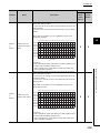
XF
YE
Module ready
YF
X10
Y10
X11
Y11
X12
Y12
X13
Y13
X14
Y14
X15
Y15
X16
Y16
X17
X18
Use prohibited
Y17
Y18
X19
Y19
X1A
Y1A
X1B
Y1B
X1C
Y1C
X1D
Y1D
X1E
Y1E
X1F
Y1F
40
Signal name
Use prohibited
CHAPTER 3 SPECIFICATIONS
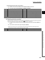
● Do not use (turn on) any "use prohibited" signals as an input or output signal to the safety CPU module.
Doing so may cause malfunction of the programmable controller system.
● For details on the I/O signals, refer to "I/O Signals". (
Page 264, Appendix 1)
3
3.4 List of I/O Signals
41
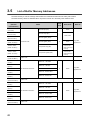
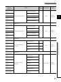
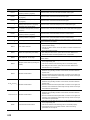
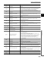
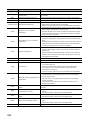
3.5
List of Buffer Memory Addresses
The buffer memory is used to exchange data between the master/local module and the safety CPU module.
The buffer memory values are defaulted when the power is turned off or the safety CPU module is reset.
Address
(Decimal
Name
(Hexadecimal))
0 to 1023
1024 to 2047
Link device area
18432 to 18463
(4800H to 481FH)
18464 to 18975
(4820H to 4A1FH)
19457
RX offset/size information
19694
19695
to
0
Read
Page 269,
Appendix 2.2
Station No. 1 RY offset
(4D00H)
19713
Station No. 1 RY size
(4D01H)
RY offset/size information
19950
to
0
Read
Page 269,
Appendix 2.3
Station No. 120 RY offset
(4DEEH)
19951
Station No. 120 RY size
(4DEFH)
42
System area
19712
(4DF0H to 4DFFH)
Link special register (SW)
• 18464 to 18495 for
read and write
• 18496 to 18975 for
read only
Appendix 2.1
Station No. 120 RX size
(4CEFH)
19952 to 19967
Link special relay (SB)
• 18432 to 18433 for
read and write
• 18434 to 18463 for
read only
Page 266,
Station No. 120 RX offset
(4CEEH)
to
Read
Station No. 1 RX size
(4C01H)
(4CF0H to 4CFFH)
0
Station No. 1 RX offset
(4C00H)
19696 to 19711
Remote register (RWr)
System area
19456
to
Read
Remote register (RWw)
(800H to 27FFH)
(4A20H to 4BFFH)
Refer to
Read, write
2048 to 10239
18976 to 19455
Read, write
Remote output (RY)
(400H to 7FFH)
(2800H to 47FFH)
value
Remote input (RX)
(0 to 3FFH)
10240 to 18431
Initial
System area
CHAPTER 3 SPECIFICATIONS
Address
(Decimal
Name
(Hexadecimal))
19968
19969
RWw offset/size information
20206
20207
20225
RWr offset/size information
20462
20463
to
20513
(5021H)
Own station (network card)
20514
information
(5022H)
20515
Page 270,
Appendix 2.5
Manufacturer code
0
Model type
1
Read
Model code
Version
(5023H)
6 or 7
Appendix 2.6
Controller information
(5028H)
valid/invalid flag
20521
Page 271,
*1
System area
20520
Manufacturer code
(5029H)
20522
Model type
(502AH)
20523
Own station (controller)
(502BH)
information
(502DH to 5036H)
Read
Model code
0
Read, write
Page 271,
Appendix 2.6
Version
Model name string
20535 to 20536
Vendor-specific device
(5037H to 5038H)
information
43
3.5 List of Buffer Memory Addresses
(5020H)
20525 to 20534
0
System area
20512
(502CH)
3
Station No. 120 RWr size
(4FEFH)
20524
Appendix 2.4
Station No. 120 RWr offset
(4FEEH)
(5024H to 5027H)
Page 270,
Station No. 1 RWr size
(4F01H)
20516 to 20519
Read
Station No. 1 RWr offset
(4F00H)
(4FF0H to 501FH)
0
System area
20224
20464 to 20511
to
Station No. 120 RWw size
(4EEFH)
to
Refer to
Station No. 120 RWw offset
(4EEEH)
(4EF0H to 4EFFH)
Read, write
Station No. 1 RWw size
(4E01H)
20208 to 20223
value
Station No. 1 RWw offset
(4E00H)
to
Initial
Address
(Decimal
Name
(Hexadecimal))
20537 to 20538
(5039H to 503AH)
value
Read, write
Refer to
System area
20544
Manufacturer code
(5040H)
20545
Model type
(5041H)
20546
Other station (network card)
(5042H)
information (station No. 1)
20547
0
Read
Model code
Page 272,
Appendix 2.7
Version
(5043H)
20548 to 20551
System area
(5044H to 5047H)
20552
Controller information
(5048H)
valid/invalid flag
20553
Manufacturer code
(5049H)
20554
Model type
(504AH)
20555
(504BH)
Other station (controller
20556
information) (station No. 1)
(504CH)
20557 to 20566
Model code
Vendor-specific device
(5057H to 5058H)
information
20569 to 20575
(5059H to 505FH)
20576 to 24383
Other station information
(5060H to 5F3FH)
(station No. 2 to No. 120)
(5F40H to 7FFFH)
*1
Read
Page 272,
Appendix 2.7
Version
20567 to 20568
24384 to 31767
0
Model name string
(504DH to 5056H)
System area
Same as other station information (station No. 1)
System area
Since the version of a master/local module is stored, the initial value depends on the master/local module used.
Do not write data to "System area".
Doing so may cause malfunction of the programmable controller system.
44
Initial
CHAPTER 4 PROCEDURES BEFORE OPERATION
CHAPTER 4
PROCEDURES BEFORE OPERATION
This chapter lists the procedures to be performed before operation of CC-Link IE Field Network.
Remark
The programming chapter in this manual provides examples for each procedure (from “System consideration” to “Debug”)
described below. (
Page 209, CHAPTER 11)
4
Check box
System consideration
Consider the system configuration and link device assignments.
Page 47, CHAPTER 5
Page 96, Section 8.1.1
Page 103, Section 8.2.1
Installation
Page 59, Section 6.1
Mount the master/local module to the safety main base unit.
Safety CPU operation mode check
QSCPU User's Manual
Check that the safety CPU module is in test mode (the TEST LED
of the safety CPU module is on) after power-on.
(Hardware Design,
Maintenance and Inspection)
Page 60, Section 6.2
Unit test
Perform a unit test on each module.
Wiring
Manual for slave stations
Page 64, Section 6.3
Connect an Ethernet cable to each module.
Cable check
Page 74, Section 6.4.2
Perform a cable test on the master/local module.
To the next page
45
Check box
Configuration
Page 77, CHAPTER 7
Set the parameters for each module.
Network diagnostics
Page 67, Section 6.4.1
Perform a loop test on the master station, and check if it can properly
communicate by the configured parameters.
Programming
Page 209, CHAPTER 11
Create a program.
Debug
Page 124, CHAPTER 9
Debug the program by using CC-Link IE Field Network diagnostics.
Safety CPU operation mode change
(to safety mode)
Change the safety CPU operation mode to safety mode using
GX Developer.
46
QSCPU User's Manual
(Hardware Design,
Maintenance and Inspection)
CHAPTER 5 SYSTEM CONFIGURATION
CHAPTER 5
5.1
SYSTEM CONFIGURATION
CC-Link IE Field Network Configuration
This section describes CC-Link IE Field Network configurations.
The master/local module operates as the following station in CC-Link IE Field Network:
• Master station (safety station)
• Local station (safety station)
• Local station (standard station)
5.1.1
5
Single network system
(1) Overall system configuration
Single network system is a system that consists of a master station and slave stations connected by Ethernet
cables.
(a) Configuring a system using safety stations only
One master station (safety station) and up to 31 local stations (safety stations) can be connected.
Switching hub
Master station
(safety station)
Local station
(safety station)
1 station
Up to 31 stations
5.1 CC-Link IE Field Network Configuration
5.1.1 Single network system
Ethernet cable
(1000BASE-T)
47
(b) Configuring a system using safety stations and standard stations
One master station (standard station) and up to 120 slave stations can be connected per network. Up to 32
safety stations can be connected per network.
Switching hub
Ethernet cable
(1000BASE-T)
Master station
(standard station)
Local station
(standard station)
1 station
Local station (safety station)
Up to 32 stations
Slave station
Up to 120 stations
When a safety station is set as a master station, the following restrictions apply:
• Some dedicated instructions cannot be used. (
Page 317, Appendix 7.2)
• Interlink transmission is not available.
The maximum number of safety connections per master/local module is as follows:
• Asynchronous mode: 31 connections
• Synchronous mode: 8 connections
48
CHAPTER 5 SYSTEM CONFIGURATION
(2) Network configuration
(a) Network topology
The network can be wired into star topology, line topology, and ring topology.
A network can consist of a combination of star and line topologies, but the ring topology cannot be combined
with star or line topology.
Switching hub
Star topology
Line topology
5
Star and line topologies mixed
Switching hub
Switching hub
Item
Description
The network is configured into a star using a switching hub and Ethernet cables.
Slave stations can be easily added to the network using this topology. (Add slave stations
Star topology
one by one. If multiple slave stations are added at a time, all stations on the network will be
reconnected. Therefore, an error may momentarily occur in all the stations.)
Data link continues with the stations that are operating normally.
The network is configured into a line by connecting the modules with Ethernet cables, but
without a switching hub. If an error occurs, stations after the faulty station will be
disconnected.*1
Line topology
Line topology
Master station (safety station)
(Station No. 0)
Stations after the faulty station are disconnected.
Fault
49
5.1 CC-Link IE Field Network Configuration
5.1.1 Single network system
Ring topology
Item
Description
The network is configured into a ring using Ethernet cables.
Data link continues with the stations that are operating normally.*1
Ring topology
The system will continue data link among
normal stations only.
Master station (safety station)
(Station No. 0)
Ring topology
Fault
*1
Add/remove slave stations one by one. If multiple slave stations are added/removed at a time, all stations on the network
will be reconnected, and an error may momentarily occur in all the stations.
(b) Station number and connection position
Modules can be connected in any order regardless of the station number.
Station No. 0
Station No. 1
Master station
( (safety
station) )
Station No. 3
Station No. 2
(c) Cascade connection
Up to 20-layer connection is available for the cascade connection.
Switching hub
Up to 20-layer
cascade connection
Remark
For wiring method, refer to
50
Page 64, Section 6.3.
CHAPTER 5 SYSTEM CONFIGURATION
(3) Precautions
(a) Connecting devices to the same network
Do not connect Ethernet devices (e.g. personal computer) other than CC-Link IE Field Network devices to the
switching hub used by CC-Link IE Field Network. Doing so will cause timeout in the master station, resulting in
disconnection of all the stations.
(b) Configuration in which data link cannot be performed (incorrectly configured ring
topology)
Do not wire devices as shown below. Doing so will cause an error in all stations and data link cannot be performed.
5
• Connecting both PORT1 and PORT2 to the switching hub
Ex.
Switching hub
Cannot connect both Ethernet ports
to the switching hub.
5.1 CC-Link IE Field Network Configuration
5.1.1 Single network system
• Ring topology through a switching hub
Ex.
Switching hub
51
(c) Ring topology
To configure a ring topology, select "Use" under "Loopback Function Setting" in the network parameter window
for the master station. (
Page 81, Section 7.3)
(d) Using a switching hub to configure a ring topology
If ring topology is configured by connecting two stations through two of the switching hub's ports, the following
problems may arise:
• If an Ethernet cable is disconnected, loopback cannot be detected.
• If a station is disconnected due to failure or power-off, data link will stop.
Therefore, do not use a switching hub to configure the ring topology.
Switching hub
(e) Offline mode station in ring topology
In the following cases, the master station or the station connected to the offline mode station cannot detect
loopback.
• One of the Ethernet cables connected to the offline mode station is disconnected.
Master station (safety station)
Station in Offline mode
No loopback is detected.
No loopback is detected.
• A station connected to the offline mode station is disconnected.
Master station (safety station)
Station in Offline mode
Fault
No loopback is detected.
No loopback is detected.
To detect loopback, set the offline mode station as a reserved station.
When the offline mode station is disconnected, loopback can be detected.
A station during the RESET status and a station with no station number setting operate as an offline mode station does.
52
CHAPTER 5 SYSTEM CONFIGURATION
(f) Connecting/disconnecting a cable and powering off/on a device
When the operations listed below are performed, all stations on the network may be reconnected.
At that time, a data link error or a baton pass error may momentarily occur in all the stations, and outputs of the
connected slave stations may turn off.
Network configuration
Operation
• Powering a slave station or switching hub off and on
• Connecting/disconnecting an Ethernet cable connected to the switching hub
• Disconnecting an Ethernet cable from a slave station and connecting it to another
Star topology
slave station or the switching hub
• Disconnecting more than nine stations, or half the number of slave stations or more in
the system
• Changing the network topology when adding a slave station
5
• Simultaneously powering off/on systems on multiple stations
• Simultaneously connecting/disconnecting Ethernet cables to/from multiple stations
Line topology, ring topology
(When a data link faulty station returns, a data link error will occur in all the stations.)
• Disconnecting more than nine stations, or half the number of slave stations or more in
the system
• Changing the network topology when adding a slave station
Momentary
error in all
the stations
5.1 CC-Link IE Field Network Configuration
5.1.1 Single network system
Insertion/removal
or power-off/power-on
To hold the outputs as a measure when a data link error occurs, configure the following settings:
• Master/local module
Set input data to be used from the faulty station.
Project data list
[Parameter]
[Network param]
[Ethernet/CC IE/MELSECNET]
button
Note that data input by safety communication is cleared even if the above setting is configured.
53
(g) Connected station numbers
Do not duplicate station numbers. Data link may be stopped when the station number is duplicated.
Duplication
Station No. 0
Station No. 1
Station No. 1
Station No. 2
(Data link may stop.)
(h) Power-on order
To avoid incorrect input from slave stations, power on slave stations before the master station.
(i) Submaster function
A master/local module cannot be used as a submaster station.
In addition, if a safety station is used in a system which includes a submaster station, an error may occur in
safety communications when the control is switched between a master station and a submaster station.
54
CHAPTER 5 SYSTEM CONFIGURATION
5.1.2
Multi-network system
The multi-network system is a system in which multiple networks are connected by some relay stations. Up to 239
networks can be connected.
CC-Link IE
Controller Network
Network No. 2
5
(Relay station)
Network No. 1
CC-Link IE
Field Network
● Safety communications can be achieved among safety stations on the same network.
● Cyclic transmission communication is available only in the same network.
● Transient transmission communication is available with other networks as well as the same network. Communications
can be made with stations up to eight networks apart (number of relay stations: 7). (
Page 154, Section 10.1 (1) (b))
55
5.1 CC-Link IE Field Network Configuration
5.1.2 Multi-network system
● Only one master/local module can be mounted on a safety base unit. Therefore, a safety programmable controller cannot
relay more than one CC-Link IE Field Network. To relay more than one CC-Link IE Field Network systems, use a
standard programmable controller.
5.2
Network Components
CC-Link IE Field Network consists of components such as cables and hubs.
5.2.1
Cables
For wiring, use the 1000BASE-T compliant Ethernet cables.
Ethernet cable
Connector
Type
The following conditioning cables:
Category 5e or higher
RJ45 connector
(Double shielded/STP) Straight cable
• IEEE802.3 (1000BASE-T)
• ANSI/TIA/EIA-568-B (Category 5e)
● For CC-Link IE Field Network wiring, use the recommended wiring components by CC-Link Partner Association.
● Cables for CC-Link IE Controller Network cannot be used for CC-Link IE Field Network.
(1) Product
Cables for CC-Link IE Field Network are available from Mitsubishi Electric System & Service Co., Ltd. (Catalogs
for cable are also available.)
Also, the connector processing of cable length is available for your preference. Please consult your local
Mitsubishi Electric System & Service Co., Ltd.
Type
CC-Link IE Field Network cable
Model (manufacturer)
SC-E5EW series (Mitsubishi Electric System & Service Co., Ltd.)
Remark
● Cable types
The following cable types are available depending on the operating environment:
• Standard type: Cables for inside the control panel and indoor connection
• L type: Cables for outdoor connection
Cables and relay adapters of flame retardant or waterproof type are also available. Please contact your Mitsubishi
Electric System & Service Co., Ltd.
56
CHAPTER 5 SYSTEM CONFIGURATION
5.2.2
Hubs
Use hubs that meet all the conditions listed below:
• Compliance with the IEEE802.3 (1000BASE-T)
• Support of the auto MDI/MDI-X function
• Support of the auto-negotiation function
• Switching hub (layer 2 switch) *1
Operation is not guaranteed if the hubs do not meet these conditions.
*1
A repeater hub is not available.
(1) Mitsubishi product
Type
Model name
Industrial switching hub
NZ2EHG-T8
5
5.2 Network Components
5.2.2 Hubs
57
5.3
Applicable Systems
This section describes MELSEC-QS series systems that include the master/local module.
Master/local module
Programming tool available for
master/local modules
Page 58, Section 5.3 (2)
Applicable CPU modules, and the
number of mountable modules
Page 58, Section 5.3 (1)
(1) Applicable safety CPU modules and the number of mountable modules
(a) Safety CPU module
The following safety CPU module is applicable to the master/local module.
Safety CPU module
Serial number (first five digits)
QS001CPU
13042 or later
(b) Number of mountable modules
For the number of mountable modules, refer to the following.
QSCPU User's Manual (Hardware Design, Maintenance and Inspection)
(c) Mounting to a MELSECNET/H remote I/O station
The master/local module cannot be mounted to any MELSECNET/H remote I/O stations. Mount the module on
a safety base unit on which a safety CPU module is mounted.
(2) Applicable programming tool
GX Developer is required for setting and diagnosing master/local modules.
GX Works2 cannot be used.
Software
Version
GX Developer
Version 8.98C or later
(3) Module replacement
Replacing the module before the following time elapses is recommended.
58
Module
Replacement time
Master/local module
10 years
CHAPTER 6 INSTALLATION AND WIRING
CHAPTER 6
INSTALLATION AND WIRING
This chapter describes the installation and wiring of a master/local module.
6.1
Installation
This section describes the installation of a master/local module.
(1) Handling precautions
The following is a list of precautions for handling the master/local module:
• Do not drop or apply strong shock to the module case since it is made from resin. Doing so may cause
failure.
• Do not remove the printed-circuit board of the module from the case. Doing so may cause failure.
• Prevent foreign matter such as dust or wire chips from entering the module. Such foreign matter can cause a
6
fire, failure, or malfunction.
• A protective film is attached to the top of the module to prevent foreign matter, such as wire chips, from
entering the module during wiring. Do not remove the film during wiring. Remove it for heat dissipation
before system operation.
• Before handling the module, touch a grounded metal object to discharge the static electricity from the human
body. Failure to do so may cause the module to fail or malfunction.
• Tighten the screws such as module fixing screws within the following range.
Screw
0.36 to 0.48N•m
• To mount the module, while pressing the module mounting lever located in the lower part of the module, fully
insert the module fixing projection(s) into the hole(s) in the base unit and press the module until it snaps into
place. Be sure to tighten the module fixing screw within the specified tightening torque range.
Incorrect mounting may cause malfunction, failure or drop of the module.
(2) Installation environment
For details on installation environment, refer to the following.
QSCPU User's Manual (Hardware Design, Maintenance and Inspection)
59
6.1 Installation
Module fixing screw (M3 × 12)
Tightening torque range
6.2
Tests Before Wiring
This section describes module tests that should be performed before network wiring.
6.2.1
Hardware test
Hardware test checks the hardware inside the master/local modules.
(1) Procedure
1.
Mount the master/local module on the safety base
unit, and connect GX Developer to the safety CPU
module.
An Ethernet cable is not connected to the master/local
modules.
2.
Set network parameters in GX Developer as
shown in the figure to left.
Select one from the followings:
"CC IE Field (Master station [Safety])",
"CC IE Field (Local station [Safety])",
or "CC IE Field (Local station)".
Project data list
param]
[Parameter]
[Network
[Ethernet/CC IE/MELSECNET]
Select "H/W test".
3.
Write the network parameters set in GX Developer
to the safety CPU module.
[Online]
4.
[Write to PLC]
Reset the safety CPU module or power off and on
the system.
or powering off
on
5.
S
T.
N
O.
The MODE LED of master/local modules flashes, and
1
100
10
60
Hardware test begins.
1
1
RUN
2
2
MODE
4
4
SD
8
8
ERR.
1
MST
each of the ×1 LED repeatedly turns on and off (1 2
D LINK
4 8 1 • • •).
RD
L ERR.
: ON
: Flashing
CHAPTER 6 INSTALLATION AND WIRING
6.
When completed
S
T.
N
O.
1
100
1
1
RUN
2
2
MODE
4
4
SD
8
8
ERR.
The ×1 LED turns off.
MST
• When failed
D LINK
Any one of the ×1 LEDs turns on, and the ERR. LED turns
RD
L ERR.
1
10
D LINK LED turns on when the test is completed.
• When completed
: ON
: Flashing
on.
When the test fails, the possible cause is hardware failure
of the master/local modules. Please consult your local
Mitsubishi service center or representative with the
When failed
S
T.
N
O.
1
100
detailed problem description.
1
1
RUN
2
2
MODE
4
4
SD
8
8
ERR.
1
10
MST
D LINK
RD
L ERR.
: ON
6
: Flashing
Remark
The test status and result can be checked through monitoring the link special relays on GX Developer.
Item
When completed
When failed
Description
• Hardware test completion status (SB0090): ON
• Hardware test normal/abnormal end (SB0091): OFF
• Hardware test completion status (SB0090): ON
• Hardware test normal/abnormal end (SB0091): ON
6.2 Tests Before Wiring
6.2.1 Hardware test
(2) Precautions
(a) Settings
Do not enter values for "Network Configuration Setting" and "Refresh parameters". When link refresh is
executed during a hardware test, the test may fail.
(b) Operations
Do not access the buffer memory through the program during the hardware test. Doing so may cause the test
to fail.
61
6.2.2
Self-loopback test
Self-loopback test checks the communication circuit of the master/local module.
When conducting the self-loopback test, use a normal Ethernet cable. (
1.
Page 56, Section 5.2)
Mount the master/local module on the safety
base unit, and connect GX Developer to the
safety CPU module.
2.
Set network parameters in GX Developer as
shown in the figure to left.
Select one from the followings:
"CC IE Field (Master station [Safety])",
"CC IE Field (Local station [Safety])",
or "CC IE Field (Local station)".
Project data list
param]
[Parameter]
[Network
[Ethernet/CC IE/MELSECNET]
Select "Self-loopback test".
3.
Write the network parameters set in GX
Developer to the safety CPU module.
[Online]
4.
[Write to PLC]
Connect PORT1 and PORT2 of the master/local
modules with an Ethernet cable. (
Page 64,
Section 6.3)
Ethernet cable
5.
Reset the safety CPU module or power off and on
the system.
or powering off
62
on
CHAPTER 6 INSTALLATION AND WIRING
6.
: ON
The MODE LED of master/local modules flashes,
: Flashing
and each of the ×10 LED repeatedly turns on and off
(1 2 4 8 1 • • •).
L ER
S
T.
N
O.
1
100
1
1
RUN
2
2
MODE
4
4
SD
8
8
ERR.
MST
P1
D LINK
LINK
RD
L ER
L ERR.
P2
Also, the SD LED, RD LED, and LINK LED turn on.
LINK
1
10
7.
When completed
S
T.
N
O.
1
100
Self-loopback test begins.
turn off when the test is completed.
1
1
RUN
2
2
MODE
4
4
SD
8
8
ERR.
• When completed
MST
The ×10 LED turns off.
D LINK
• When failed
RD
L ERR.
1
10
D LINK LED turns on, and SD LED and RD LED
: ON
: Flashing
Any one of the ×10 LEDs turns on, and the ERR. LED
turns on. If the test fails, replace the Ethernet cable and
6
execute the test again. If the test fails again, the
possible cause is hardware failure of the master/local
When failed
modules. Please consult your local Mitsubishi service
center or representative with the detailed problem
S
T.
N
O.
1
100
1
1
RUN
2
2
MODE
4
4
SD
8
8
ERR.
1
description.
D LINK
RD
L ERR.
: ON
: Flashing
6.2 Tests Before Wiring
6.2.2 Self-loopback test
10
MST
Remark
The test status and result can be checked through monitoring the link special relays on GX Developer.
Item
When completed
When failed
Description
• Self-loopback test completion status (SB0092): ON
• Self-loopback test normal/abnormal end (SB0093): OFF
• Self-loopback test completion status (SB0092): ON
• Self-loopback test normal/abnormal end (SB0093): ON
63
6.3
Wiring
This section describes the cable wiring and precautions. For network configuration, cables, and hubs used for the
wiring, refer to the system configuration. (
Page 47, CHAPTER 5)
(1) Ethernet cable connection
(a) Connecting the cable
1.
Power off the master/local module and the
connected device.
2.
Push the Ethernet cable connector into the
master/local module until it clicks. Pay attention to
the connector's direction.
3.
Power on the master/local module and the
connected device.
4.
Check whether the LINK LED of the port connected
L ER
with an Ethernet cable is on.
P1
The time between the power-on and the LINK LED
LINK
turning on may vary. The LINK LED usually turns on in a
few seconds. Note, however, that the time may be
extended further if the linkup process is repeated
depending on the status of the device on the line.
If the LINK LED does not turn on, refer to the
troubleshooting section and take corrective actions.
(
64
Page 239, Section 12.3)
CHAPTER 6 INSTALLATION AND WIRING
PORT1 and PORT2 need not to be distinguished.
• When only one connector is used in star topology, either PORT1 or PORT2 is applicable.
L ER
P1
LINK
Either one can be used.
L ER
P2
LINK
QS0J71GF11-T2
• When using two connectors for line topology and ring topology, an Ethernet cable can be connected to the
connectors in any combination. For example, the cable can be connected between PORT1s or between PORT1
and PORT2.
Connection between
PORT1s or PORT2s
Connection between
PORT1 and PORT2
L ER
L ER
L ER
L ER
L ER
L ER
P1
P1
P1
P1
P1
P1
LINK
LINK
LINK
LINK
LINK
LINK
L ER
L ER
L ER
L ER
L ER
L ER
P2
P2
P2
P2
P2
P2
LINK
LINK
LINK
LINK
LINK
LINK
QS0J71GF11-T2
QS0J71GF11-T2
QS0J71GF11-T2
QS0J71GF11-T2
QS0J71GF11-T2
6
QS0J71GF11-T2
(b) Disconnecting the cable
Power off the system.
Press the latch down and unplug the Ethernet cable.
65
6.3 Wiring
1.
2.
(2) Precautions
This section describes wiring precautions.
(a) Handling
• Place the Ethernet cable in a duct or clamp them. If not, dangling cable may swing or inadvertently be pulled,
resulting in damage to the module or cables or malfunction due to poor contact.
• Do not touch the core of the cable-side or module-side connector, and protect it from dirt or dust. If oil from
your hand, dirt or dust is attached to the core, it can increase transmission loss, arising a problem in data
link.
• Check the following:
• Is any Ethernet cable disconnected?
• Is any of the Ethernet cables shorted?
• Are the connectors securely connected?
(b) Broken cable latch
Do not use Ethernet cables with broken latches. Doing so may cause the cable to unplug or malfunction.
(c) Connecting and disconnecting the Ethernet cable
Hold the connector part when connecting and disconnecting the Ethernet cable. Pulling a cable connected to
the module may damage the module or cable, or result in malfunction due to poor contact.
(d) Connectors without Ethernet cable
Attached connector cover should be placed to prevent foreign matter such as dirt or dust.
(e) Maximum station-to-station distance (maximum cable length)
The maximum station-to-station distance is 100m. However, the distance may be shorter depending on the
operating environment of the cable. For details, contact your cable manufacturer.
(f) Bend radius
The bend radius of the Ethernet cable is limited. For details, see the specifications of the Ethernet cable to be
used.
(g) Network configuration
For wiring, check Page 49, Section 5.1.1 (2) and Page 51, Section 5.1.1 (3) to prevent incorrect wiring
66
CHAPTER 6 INSTALLATION AND WIRING
6.4
Tests After Wiring
This section describes loop and cable tests that should be performed after network wiring.
Perform these tests to the actual operating network configuration.
6.4.1
Loop test
The loop test checks each station's network line and parameter setting status to verify whether the network is
operating correctly.
The test completes approximately in 10 seconds.
Start testing from the master station. To use a standard programmable controller for the master station, refer to the
following manual.
User’s manual for the CC-Link IE Field Network master/local module used
6
The test allows checking of the following items:
Item
Description
Master station duplication check
Checks if the master station is duplicated.
Station number duplication check
Checks if stations on the network are duplicated.
Out-of-range station No. check
Reserved station specification
check
Checks if the number of connected slave stations exceeds the number of slave stations
set to the master station.
Checks if the specified reserved stations are actually connected.
Consistency check for the number of total slave stations set by parameters and actual
of connected stations
connected slave stations.
Station type check
Loopback check
Consistency check for the station type of slave stations set in master stations and actual
connected station type.
Detects whether loopback is being performed when "Use" is selected under "Loopback
Function Setting" in the network parameter window for the master station.
(1) Performing a loop test
This section describes the procedure using the following system configuration example.
Master station
(safety station)
Local station
(safety station)
Local station
(safety station)
Local station
(safety station)
67
6.4 Tests After Wiring
6.4.1 Loop test
Consistency check of the number
(a) Preparing for a loop test
After wiring, set the local stations (safety stations) to online mode before executing the loop test.
1.
2.
Connect GX Developer to the CPU module.
Set the local stations (safety stations) to online
mode by GX Developer.
Master station
(safety station)
Local station (safety station)
Ex. In the case of a local station (safety station)
Select
"CC IE Field (Local
station [Safety])".
Select "Online."
3.
Reset the slave stations or power off and on to
set the mode to online.
Remark
For slave stations other than the local station where the master/local module is mounted, also set their mode to online. For
the setting method of slave stations, refer to the manual of the slave station used.
68
CHAPTER 6 INSTALLATION AND WIRING
(b) Procedure
Perform a loop test from the master station (safety station).
1.
Connect GX Developer to the safety CPU module.
2.
Set network parameters in GX Developer as
Master station
(safety station)
shown in the figure to left.
Select
"CC IE Field (Master
station [Safety])".
Project data list
param]
[Parameter]
[Network
6
[Ethernet/CC IE/MELSECNET]
Select "Loop test".
3.
Configure the network configuration setting in the
network parameter. (
Project data list
param]
Page 81, Section 7.3)
[Parameter]
[Network
[Ethernet/CC IE/MELSECNET]
4.
Write the network parameters set in GX Developer
to the safety CPU module.
[Online]
5.
[Write to PLC]
Reset the safety CPU module or power off and on
the system.
or powering off
on
6.
Master station (safety station)
Loop test begins.
• Master station (safety station)
Local station (safety station)
The MODE and D LINK LEDs flash. Also, each of the
S
T.
N
O.
1
100
10
1
1
RUN
2
2
MODE
4
4
SD
8
8
ERR.
1
S
T.
N
O.
1
1
RUN
2
2
MODE
RD
4
4
SD
L ERR.
8
8
MST
D LINK
1
100
10
ERR.
MST
D LINK
RD
L ERR.
×10 LED and ×1 LED repeatedly turns on and off (1 2
4 8 1 • • •).
However, if errors are detected, the test is immediately
terminated (failure).
1
: ON
: Flashing
• Local station (safety station)
Data link stops on all stations. Also, the MODE, D LINK,
and ×100 LEDs flash.
69
6.4 Tests After Wiring
6.4.1 Loop test
button
7.
When completed
S
T.
N
O.
1
100
station (safety station). D LINK LED turns on when
1
1
RUN
2
2
MODE
4
4
SD
8
8
ERR.
the test is completed.
MST
• When completed
D LINK
The ×10 and ×1 LEDs turn off.
RD
L ERR.
1
10
: ON
: Flashing
1
100
10
• When failed
Any one of the ×10 and ×1 LEDs turns on, and the ERR.
LED turns on. Error details can be specified depending
on the lighting status of ×10 and ×1 LEDs.
When failed
S
T.
N
O.
Check the test result with LEDs of the master
1
1
RUN
2
2
MODE
4
4
SD
8
8
ERR.
MST
1
1
Master station duplication
D LINK
2
2
Station No. duplication
RD
4
4
Invalid station No.
8
8
10
1
L ERR.
1
: ON
: Flashing
Reserved station specification error
(A station that exists on the network is set
as a reserved station in the master station.)
Loopback stations exist.
Station type setting error
Inconsistent number of total slave
stations
All stations faulty
Identify the error location through GX Developer or
link special register (SW), and take actions.
(
8.
Page 72, Section 6.4.1 (2))
When the loop test is completed, slave stations
will be in online mode.
Set the master station (safety station) to "Online
Select "Online
(Normal Mode)"
or "Online
(High Speed Mode)".
Write the network
parameters to the
Safety CPU module.
or Power OFF
ON
During the loop test, data link stops on all stations.
70
(Normal Mode)" or "Online (High Speed Mode)"
through the network parameter.
CHAPTER 6 INSTALLATION AND WIRING
Remark
The test status and result can be viewed through monitoring the link special relays on GX Developer.
Item
When completed
When failed
Description
• Loop test completion status (SB0094): ON
• Loop test normal/abnormal end (SB0095): OFF
• Loop test completion status (SB0094): ON
• Loop test normal/abnormal end (SB0095): ON
6
6.4 Tests After Wiring
6.4.1 Loop test
71
(2) Actions if the loop test fails
(a) Checking by GX Developer
In the CC-Link IE Field Network diagnostics, identify the error location and take action. Then, execute the loop
test again.
1.
Open the "CC IE Field Diagnostics" window.
[Diagnostics]
2.
[CC IE Field diagnostics]
The error location is displayed on top of the
diagnostic window.
3.
Click the error location.
4.
Click the button on the bottom right of the window
Click
to display the error descriptions.
5.
Reset the safety CPU module on the master station
(safety station) or power off and on the system to
or powering off
on
retry the loop test.
With CC-Link IE Field Network diagnostics, a station where network number mismatch, master station duplication, station
number duplication, or station type error occurs cannot be selected. Check the error details by directly connecting GX
Developer to the faulty station and displaying the system monitor window. (
72
Page 261, Section 12.6)
CHAPTER 6 INSTALLATION AND WIRING
(b) Checking by link special register (SW)
Identify the error location by link special register (SW) and take actions. After the actions, execute the loop test
again.
1.
Check the error locations and descriptions by link special register (SW), and take actions.
Error cause
Action
Master station duplication, station number
Parameter error status (each station) (SW0170 to SW0177) checks error
duplication, out-of-range station No.,
locations.
reserved station specification, or station
Take corrective actions by checking error codes on Parameter setting status
type
(SW004C). (
Page 246, Section 12.5)
Identify the error stations on baton pass status (each station) (SW00A0 to
SW00A7). The following actions are taken on error stations.
• Replace the Ethernet cable.
• Adjust the total number of slave stations set to the master station (safety
All station errors or inconsistent number of
station) to the number of connected slave stations.
connected stations
• Check if the station set in the network configuration setting of GX Developer
matches with the connected station.
• Set the station number for the station where a station number is not set.
6
• Replace the master/local modules.
The network is not configured in ring topology or is incorrectly configured.
(
Page 49, Section 5.1.1 (2))
Check connection status of stations between the stations specified at Loopback
Loopback stations exist.
station number 1 (SW0070) and Loopback station number 2 (SW0071), and
connected Ethernet cables.
To use a network configuration other than the ring topology, clear the "Use"
checkbox under "Loopback Function Setting" in the network parameter window
for the master station (safety station).
Reset the safety CPU module on the master station (safety station) or power off and on the system
to retry the loop test.
73
6.4 Tests After Wiring
6.4.1 Loop test
2.
6.4.2
Cable test
Cable test checks if the Ethernet cables are properly connected.
Only the Ethernet cable connected to the PORT1 or PORT2 of the target station is tested. For the whole network
status, perform the loop test. (
Page 67, Section 6.4.1)
1.
Connect GX Developer to the safety CPU
module.
Station No. 0
Station No. 1
Station No. 2
Station No. 3
2.
Open the "Cable Test" window.
[Diagnostics]
[CC IE Field diagnostics]
button
3.
Enter a station number and click the
button to operate the test. If an error occurs, take
corrective actions according to the error
message.
74
CHAPTER 6 INSTALLATION AND WIRING
6.4.3
Communication test
Communication test checks if transient transmission data can be properly routed from the own station to the
communication target.
Take the following system configuration as an example of communication test procedure.
CC-Link IE
Field Network
CC-Link IE
Field Network
Own station
(request source)
Station
No. 2
Station
No. 0
Network No. 1
Station
No. 1
Station
No. 3
Station
No. 0
Station
No. 2
Network No. 3
(Relay
station 2)
Station Station
Station
No. 2
No. 3
No. 4
(Relay
station 1)
Station
No. 0
Communication
target
Network No. 2
6
Station
No. 1
CC-Link IE
Field Network
GX Developer
CC-Link IE
Field Network
1.
Connect GX Developer to the safety CPU module.
2.
Set routing parameters in GX Develoepr as shown in
CC-Link IE
Field Network
Station
No. 2
Station
No. 0
Network No. 1
Station
No. 1
Station
No. 3
Station
No. 0
(Relay
station 1)
Station
No. 0
(Relay
station 2)
Station
No. 2
Network No. 2
6.4 Tests After Wiring
6.4.3 Communication test
Own station
(request source)
Station
No. 2
Network No. 3
Station
No. 3
Station
No. 4
Communication
target
Station
No. 1
CC-Link IE
Field Network
Routing parameters for stations of network No. 1
the figure to left. (
No setting is required for station
No. 3 because data are transmitted
via the station itself.
Routing parameters for stations of network No. 2
No setting is required for station
No. 0 because data are transmitted
via the station itself.
Project data list
param]
Page 92, Section 7.7)
[Parameter]
[Network
[Ethernet/CC IE/MELSECNET]
button
No setting is required for station
No. 2 because data are transmitted
via the station itself.
Routing parameters for stations of network No. 3
No setting is required for station
No. 3 because data are transmitted
via the station itself.
75
3.
Write the network parameters set in GX Developer
to the safety CPU module.
[Online]
4.
[Write to PLC]
Reset the safety CPU module or power off and on
the system.
or powering off
on
5.
Open the "Communication Test" window and enter
values for "Target Station" and "Communication
Data Setting".
[Diagnostics]
[CC IE Field diagnostics]
button
6.
Click the
button to perform the
communication test. If an error occurs, take actions
according to the error message.
When conducting the test on relay stations, set the receiving (relay) station in "Target Station". Setting the sending (relay)
station will cause an error.
Network No. 1
Station
No. 0
Own station
(request source)
76
Station
No. 1
Network No. 2
Station
No. 2
Receiving
Sending
(relay) station (relay) station
Station
No. 0
CHAPTER 7 PARAMETER SETTING
CHAPTER 7
PARAMETER SETTING
This chapter describes CC-Link IE Field Network parameters.
The network parameters are set for either the master station or slave stations.
This manual describes network parameters for master/local modules. For slave station settings, refer to the manuals
for the slave stations used.
7.1
Parameter List
The following table lists CC-Link IE Field Network parameters.
(1) Parameters set for a master/local module
The following table lists parameters that need to be set for safety and standard communications.
7
1
2
3
4
7.1 Parameter List
5
6
: Always,
: When required, : Cannot be set
Setting
Item
Master
Local
Local
station
station
station
(safety
(safety
(standard
station)
station)
station)
Reference
Network type
Starting I/O No.
1
Network setting
Network No.
Page 79, Section
Total stations
Station No.
7.2
Mode
77
Setting
Master
Local
Local
station
station
station
(safety
(safety
(standard
station)
station)
station)
RWw/RWr Setting*1
Reserved/Error Invalid Station
Alias
Page 81, Section
Comment
7.3
Item
Station No.
Station Type
RX/RY
2
Network Configuration
Setting
Setting*1
Link Scan Mode
Setting
Supplementary
Setting
Loopback Function
Setting
Reference
Block Data
Assurance per
Station
Parameter Name
3
Network Operation
Setting
4
5
7.4
Output Setting During CPU STOP
Page 86, Section
Refresh parameters
Safety Communication
Setting
6
Page 85, Section
Data Link Faulty Station Setting
Routing parameters
*1
7.5
Communication Target Station No.
Open Method
Transmission Interval Monitoring Time
Safety Refresh Monitoring Time
Safety Data Transfer Device Setting
Page 90, Section
7.6
Page 92, Section
7.7
This parameter needs to be set for standard communication (needs not to be set for safety communication).
Always set parameters. Failure to do so will cause "NETWORK PARAMETER ERROR" in the safety CPU module.
78
CHAPTER 7 PARAMETER SETTING
7.2
Network Setting
Set the network number, station number, and other parameters for the master/local module.
(1) Setting procedure
1.
Open the setting window in GX Developer.
Project data list
2.
3.
[Parameter]
[Network param]
[Ethernet/CC IE/MELSECNET]
Set parameters in the window.
Click the
button.
7
Description
Select whether to use the master/local module as a master station
Network type
(safety station) or a local station.
Only one master station (safety station) can be set for one network.
Starting I/O No.
Network No.
Setting range
• CC IE Field (Master station [Safety])
• CC IE Field (Local station [Safety])
• CC IE Field (Local station)
(Default: Blank)
Enter the start I/O number of the master/local module in increments of
Within the number of I/O points of the
16 points.
safety CPU module (Default: Blank)
Enter the network number of the master/local module.
1 to 239 (Default: Blank)
Enter the number of slave stations connected to the master station
Total stations
(safety station) including reserved slave stations.
This setting is available when "CC IE Field (Master Station [Safety])" is
1 to 120 (Default: Blank)
selected in "Network type".
Enter the station number of the master/local module. Set a station
Station No.
number different from those used in the same network.
Note that the master station (safety station) number is fixed at "0".
• Master station (safety station): Fixed
at "0".
• Local station: 1 to 120
(Default: Blank)
79
7.2 Network Setting
Item
Item
Description
Setting range
Select a master station (safety station) mode.
Two online modes are available. Select an online mode according to
the system.
Mode
Description
Online (Normal Mode)
This mode performs cyclic transmission and
transient transmission without losing their inherent
speed performance. This mode is suitable for a
system that performs I/O control and analog
control, and transmits large amount of data for
management, monitoring, and diagnostics by
transient transmission.
Use this mode for general applications.
Online (High Speed
Mode)
This mode preferentially performs cyclic
transmission for high-speed communications.
Note that the maximum number of points assigned
to RWw/RWr is 256 points per local station.
In this mode, the processing speed of transient
transmission is slower than in "Online (Normal
Mode)".
• Online (Normal Mode)
• Online (High Speed Mode)
• Offline
• H/W test
• Self-loopback test
• Loop test
(Default: Online (Normal Mode))
Select this mode to disconnect the master/local
module from the network for stopping data link with
other stations.
Offline
Mode
H/W test
Self-loopback test
Loop test
Select this mode to perform a hardware test.
(
Page 60, Section 6.2.1)
Select this mode to perform a self-loopback test.
(
Page 62, Section 6.2.2)
Select this mode to perform a loop test.
(
Page 67, Section 6.4.1)
Select a local station mode.
Mode
Description
Online
Select this mode to connect the master/local
module to the network for performing data link with
other stations.
Offline
Select this mode to disconnect the master/local
module from the network for stopping data link with
other stations.
H/W test
Self-loopback test
Select this mode to perform a hardware test.
(
Page 60, Section 6.2.1)
Select this mode to perform a self-loopback test.
(
Page 62, Section 6.2.2)
(2) Setting example
For setting example, refer to
80
Page 209, CHAPTER 11.
• Online
• Offline
• H/W test
• Self-loopback test
(Default: Online)
CHAPTER 7 PARAMETER SETTING
7.3
Network Configuration Setting
Set parameters of slave stations (the number of points and assignment of link devices) in the master station (safety
station). Also, set link scan mode and block data assurance per station.
This setting is available when "CC IE Field (Master Station [Safety])" is selected in network setting.
(1) Setting procedure
1.
2.
Configure network setting. (
Page 79, Section 7.2)
Open the setting window in GX Developer.
Project data list
[Parameter]
[Network param]
[Ethernet/CC IE/MELSECNET]
button
3.
4.
Set parameters in the window.
Click the
button.
7
Description
Select a link device assignment method.
Assignment Method
• Points/Start: Enter the points and start numbers of link devices.
• Start/End: Enter the start and end numbers of link devices.
Number of PLCs
7.3 Network Configuration Setting
Item
Setting range
• Points/Start
• Start/End
(Default: Start/End)
Displays the number of slave stations set for "Total Stations" in
network setting.
1 to 120
Station No.
Enter the number of a slave station connected to the network.
(Starting from 1 (default), numbers are
Station numbers can be set at random (cannot be duplicated).
displayed by the value set in "Total
stations" in network setting.)
• Remote I/O Station
Station Type
Select a slave station type. Select the station type same as that of the
slave station connected to the network.
• Remote Device Station
• Intelligent Device Station
• Local Station
(Default: Intelligent Device Station)
81
Item
Description
Setting range
• Points:
Station Type
Set assignment for RX/RY for each slave station. (
RX/RY Setting
Page 103,
Section 8.2.1)
Enter values in increments of 16 points (Start: 0H, End:
FH).
Setting
range
Local Station, Intelligent
Device Station
16 to 2048
Remote Device Station
16 to 128
Remote I/O Station
16 to 64
• Device number: 0 to 3FFFH
(Default: Blank)
• Points:
Station Type
RWw/RWr Setting
Setting
range
Set assignment for RWw/RWr in increments of 4 points for each slave
Local Station, Intelligent
Device Station
4 to 1024
station. (
Remote Device Station
4 to 64
Remote I/O Station
Cannot be
set.
Page 103, Section 8.2.1)
• Device number: 0 to 1FFFH
(Default: Blank)
Link devices of the master/local module to be transferred by link
refresh and the transfer target safety CPU module devices are
Refresh Device
displayed.
This item is displayed when refresh parameters have been set.
(
Page 86, Section 7.5)
Set this item to reserve the slave station or to set the slave station as
an error invalid station. (
Page 119, Section 8.4, Page 120,
Section 8.5)
• No Setting
The slave station is connected to the network.
• Reserved Station
The slave station is reserved for future expansion. By reserving a
slave station, link device assignment will not change even if the
• No Setting
Reserved/Error Invalid
slave station is added or the reservation is cancelled. Therefore, the
• Reserved Station
Station
program needs not to be modified. Physical connection of the slave
station is not required.
• Invalid Station
(Default: Blank)
• Invalid Station
Even if a slave station is disconnected during data link, the master
station (safety station) will not detect the slave station as a faulty
station. However, if a local station (safety station) set as an error
invalid station or a temporary error invalid station is disconnected,
an error will occur in safety communication with the disconnected
station.
Alias
Enter the name of a device on the slave station if required.
Comment
Enter the comment of the slave station if required.
82
Up to 8 characters
(Default: Blank)
Up to 32 characters
(Default: Blank)
CHAPTER 7 PARAMETER SETTING
Item
Description
Setting range
Set link scan mode and block data assurance per station.
(1)
Link Scan Mode Setting
Item
Description
Link scan is performed asynchronously with the
sequence scan of the safety CPU module.
Select this item to shorten input transmission delay
time when sequence scan takes much time than link
scan. Note that output transmission delay time will
become longer.
Asynchronous
button
Constant Scan
Cyclic transmission is performed punctually. Link scan
time will be the constant link scan time set in this
setting.
However, when the actual link scan time is longer than
the specified link scan time, cyclic transmission is
performed by actual link scan time.
Asynchronous, Synchronous
7
(Default: Asynchronous)
• Loopback Function Setting:
Selected (Use)/not selected
(Default: Not selected)
• Block Data Assurance per Station:
Selected (Assure Block Data)/not
7.3 Network Configuration Setting
While constant link scan is used to keep link scan time
constant, the transmission delay time is not kept
constant by this function. To keep transmission delay
time constant, select "Synchronous".
• Link Scan Mode Setting:
selected
(Default: Selected)
Link scan is performed synchronously with the
sequence scan of the safety CPU module. Select this
item in the following cases:
• To shorten output transmission delay time (Note
that when sequence scan takes much time than link
scan, input transmission delay time will become
longer.)
Synchronous
• To keep transmission delay time constant*1
*1
(2)
The sequence scan must be constant as well.
Set "Constant Scanning" in the "PLC RAS" of the
PLC Parameter window.
Loopback Function Setting
Select whether to use the loopback function. (
Page 121,
Section 8.6) To configure a network in ring topology, select the
checkbox.
(3)
Block Data Assurance per Station
Select whether to assure data integrity on a station basis in link
refresh between the safety CPU module and the master/local
module. (
Page 106, Section 8.2.3)
83
Item
Description
Setting range
Equally assign link devices to slave stations with preset conditions.
• Start station: 1 to the end slave
station number
• End station: Number set to "Start
station" to the end slave station
number
Item
button
Description
Start station
Enter the start station number of slave stations for which
link devices are equally assigned.
End station
Enter the end station number of slave stations for which
link devices are equally assigned.
Start No.
Enter the start number of link devices to be equally
assigned.
Total points
assigned
Enter the total points of link devices to be equally
assigned.
• Start No.: Same values set in "RX/RY
Setting" and "RWw/RWr Setting"
• Total points assigned: Same values
set in "RX/RY Setting" and
"RWw/RWr Setting"
(Default: Blank)
Assign the same link device points to all slave stations. Enter the
points in the field right next to the
button.
button
Points entered in this field will be reflected to the "Points" of "RX/RY
Setting".
Half of the points entered in this field will be reflected to the "Points" of
"RWw/RWr Setting".
(2) Precautions
When "Synchronous" is set under "Link Scan Mode Setting" of "Supplementary Setting", observe the following.
• Change the program or the system configuration so that the sequence scan time of the safety CPU module
may be within 200ms. Failure to do so may cause disconnection of slave stations.
• Set the sequence scan time of safety CPU modules on local stations (safety stations) so that it may be
longer than or equal to the link scan time.
If the sequence scan time is shorter than the link scan time, an error occurs in safety communication. To
avoid this, set the constant scan time of the safety CPU modules on the local stations (safety stations).
For how to calculate link scan time, refer to
Page 303, Appendix 5.2.
For how to set the constant scan time of a safety CPU module, refer to the following.
QSCPU User’s Manual (Function Explanation, Program Fundamentals)
(3) Setting example
For setting example, refer to
84
Page 209, CHAPTER 11.
CHAPTER 7 PARAMETER SETTING
7.4
Network Operation Setting
Set operating status of a network if a data link error occurs or the safety CPU module is set to STOP.
1.
2.
Configure network setting. (
Page 79, Section 7.2)
Open the setting window in GX Developer.
Project data list
[Parameter]
[Network param]
[Ethernet/CC IE/MELSECNET]
button
3.
Set parameters in the window.
7
Parameter Name
Description
Enter the name of network operation setting parameters if desired.
Select whether to hold or clear data input by standard communication
Data Link Faulty Station
Setting
Output Setting During
CPU STOP
from the slave station where a data link error has occurred.
(
Page 113, Section 8.2.5)
Setting range
Up to 8 characters
• Turn OFF or 0 Clear Input Data
(RX/RY)
• Hold Input Data (RX/RY)
Data input by safety communication will be cleared regardless of this
(Default: Turn OFF or 0 Clear Input
setting and safety CPU operation mode.
Data (RX/RY))
Select whether to hold or clear cyclic data output when the safety CPU
module mounted with the master/local module is set to STOP.
(
Page 115, Section 8.2.6)
7.4 Network Operation Setting
Item
• Hold
• Clear (ALL OFF)
(Default: Hold)
85
7.5
Refresh Parameters
Set the ranges of link devices of the master/local module and safety CPU module devices for which link refresh is to be
performed.
(1) Setting procedure
1.
2.
Configure network setting. (
Page 79, Section 7.2)
Open the setting window in GX Developer.
Project data list
[Parameter]
[Network param]
[Ethernet/CC IE/MELSECNET]
button
3.
4.
Item
Set parameters in the window.
Click the
button.
Description
Select a link device assignment method.
Assignment method
• Points/Start: Enter the points and start numbers of link devices.
• Start/End: Enter the start and end numbers of link devices.
86
Setting range
• Points/Start
• Start/End
(Default: Start/End)
CHAPTER 7 PARAMETER SETTING
Item
Description
Setting range
Select link refresh ranges of SB and SW. Link refresh range can be
set for both "Transfer SB" and "Transfer SW" by 1. (
Page 104,
Section 8.2.2)
Dev. name
(1)
Transfer SB
• Link side: Fixed at "SB".
• PLC side: M, B, D, W, SB
Ex.
(2)
Transfer SW
• Link side: Fixed at "SW".
• PLC side: M, B, D, W, SW
(Default: Blank)
Transfer SB
0000H
Transfer
01FFH
SW
0000H
01FFH
Points,
Device
name
(SB)
Device
name
(SW)
Transfer
SB
Transfer
SW
Device
name
(SB)
Device
name
(SW)
0000H
01FFH
0000H
• Link side: 0 to 1FFH
• PLC side: Within device range of
01FFH
safety CPU module
(Default: Blank)
Start, End
Set bit devices in increments of 16
points and word devices in increments
of 4 points.
Master/local module
Safety CPU module
Select link refresh ranges of RX, RY, RWr, and RWw. Link refresh
• Link side: RX, RY, RWr, RWw
ranges can be set up to 8. (
• PLC side:
Page 104, Section 8.2.2)
7
When RX is set to “Link Side”:
Ex.
X, M, B, D, W
When RY is set to “Link Side”:
Y, M, B, T, C, ST, D, W
Dev. name
7.5 Refresh Parameters
When RWr is set to “Link Side”:
M, B, D, W
0000H
00FFH
Transfer 1
0000H
to 8
00FFH
0000H
00FFH
Points,
Start, End
0000H
00FFH
Device
name
(RX)
Device
name
(RY)
Device
name
(RWr)
Device
name
(RWw)
Transfer
1
Transfer
2
Transfer
3
Transfer
4
Device
name
(X)
Device
name
(Y)
Device
name
(W)
Device
name
(W)
1000H
When RWw is set to “Link Side”:
M, B, T, C, ST, D, W
10FFH
(Default: Blank)
1000H
10FFH
0000H
• Link side:
0 to 3FFFH for RX/RY
00FFH
0100H
0 to 1FFFH for RWr/RWw
• PLC side: Within device range of
safety CPU module
01FFH
(Default: Blank)
Set bit devices in increments of 16
points and word devices in increments
of 4 points.
Master/local module
button
Reset refresh parameters to default.
Safety CPU module
87
(2) Checking method
1.
Clicking the
button in the "Network parameters Setting the number of Ethernet/CC
IE/MELSECNET cards." window will open the "assignment image" window.
(
2.
Page 79, Section 7.2)
Select a device to be displayed and the magnification ratio in the window, and check the image of
refresh parameter assignment.
1) Click
2) Set
"Device (PLC side)",
"Device (Link side)", and
"Display magnification".
3) The assignment
image is displayed.
3.
A red part in the CPU side device indicates that the device in the red part overlaps with the device
set for another refresh parameter. Correct the refresh parameters.
88
CHAPTER 7 PARAMETER SETTING
(3) Precautions
(a) Device set to "Device (PLC side)"
Set a device range that differs from the one used for the following:
• Refresh parameters for other network modules
• Auto refresh parameters for CC-Link Safety master module
• I/O numbers used for network modules
(b) Link refresh range
Set only link devices used in the safety CPU module for link refresh range. Doing so will reduce link refresh
points, resulting in a shorter link refresh time.
(c) Changing link device assignment in the "Network Configuration Setting" window
Correct the link refresh ranges of refresh parameters.
(4) Setting example
For setting example, refer to
Page 209, CHAPTER 11.
7
7.5 Refresh Parameters
89
7.6
Safety Communication Setting
Set safety communication parameters for stations that perform safety communication.
This setting can be configured when "CC IE Field (Master station [Safety])" and "CC IE Field (Local station [Safety])"
are set in network setting.
(1) Setting procedure
1.
Open the setting window in GX Developer.
Project data list
[Parameter]
[Network param]
[Ethernet/CC IE/MELSECNET]
button
2.
3.
Set parameters in the window.
Click the
button.
Item
Description
Select how to assign safety CPU module devices.
Assignment Method
• Points/Start: Set devices by the number of device points and the
start number.
• Start/End: Set devices by the start and last device numbers.
Setting range
• Points/Start
• Start/End
(Default: Start/End)
When “CC IE Field (Master station [Safety])” is selected in network
setting, the number of slave stations set in “Total stations” is
Total Number of Stations
displayed.
When “CC IE Field (Local station [Safety])” is selected in network
setting, the number of slave stations is not displayed.
When “CC IE Field (Master station [Safety])” is selected in network
setting, “0” is displayed.
Host Station No.
When “CC IE Field (Local station [Safety])” is selected in network
setting, own station number set to “Station No.” in network setting is
displayed.
90
CHAPTER 7 PARAMETER SETTING
Item
Description
Transmission Interval
Monitoring Time
Setting range
In each safety connection, batch-set monitoring time for a receiving
station to detect safety communication errors.
(
1 to 1000
(Default: 25)
Page 308, Appendix 5.4)
• Master station (safety station):
Communication Target Station
No.
1 to 120
Set the communication target’s station number.
• Local station: 0 to 120
(Default: Blank)
Select how to establish safety connection.
• Active: Establishes safety connection from the own station.
Open Method
• Passive: Establishes safety connection upon request from the
communication target station.
• Active
• Passive
(Default: Active)
In each safety connection, set monitoring time for a receiving station
Safety Refresh Monitoring
to detect safety communication errors.
2 to 2000
Time (ms)
Set this item for the Active side of the stations that perform safety
(Default: 60)
communication. (
Page 309, Appendix 5.5)
Set a CPU module device where safety data are stored.
• Device Name: X, M, B, D, W
Ex.
• Points:
Device
0000H
Receive
Data
007FH
Storage
Device
name
(X)
Device
Safety data
reception
Range
Bit devices
16 to 128
Word devices
1 to 8
Device range of the
safety CPU module
Start
End
Device
7
(Default: Blank)
Set bit devices in units of 16
points and word devices in units
Transfer Device
Safety CPU module
(communication target station)
of 1 points.
Set a CPU module device from where safety data are sent.
Setting
• Device Name: Y, M, B, T, C,
Ex.
ST, D, W
• Points:
Device
0000H
Send Data
001FH
Storage
Device
name
(Y)
Device
Device
Safety data
transmission
Range
Bit devices
16 to 128
Word devices
1 to 8
Start
End
Device range of the
safety CPU module
(Default: Blank)
Set bit devices in units of 16
points and word devices in units
Safety CPU module
(own station)
Safety CPU module
(communication target station)
Batch-set “Safety Refresh Monitoring Time”. (
button
Appendix 5.5)
of 1 points.
Page 309,
2 to 2000 (Default: Blank)
Enter the time in the area right to the
button.
91
7.6 Safety Communication Setting
Safety CPU module
(own station)
Safety Data
7.7
Routing Parameters
Set communication paths for transient transmission between a station in the own network and stations in other
networks.
(1) Setting procedure
1.
Open the setting window in GX Developer.
Project data list
[Parameter]
[Network param]
[Ethernet/CC IE/MELSECNET]
button
2.
3.
Set parameters in the window.
Click the
button.
Item
Description
Setting range
Set a relay station through which data are sent to stations in other networks by
transient transmission in the own network. Up to 8 communication paths can
be set.
Target network No.
1 to 239 (Default: Blank)
Set routing parameters as shown below.
Ex. Setting to transmit data to network number ● by transient transmission
To go to network No.
, data passes through station No.
of its own network No.
Relay network No.
.
1 to 239 (Default: Blank)
No routing parameter setting is required for
network No.
because the module of
network No.
is mounted on the relay station.
Station that needs
routing parameters*1
Relay station No.
Network No.
(Relay station)
Network No.
92
0 to 120 (Default: Blank)
CHAPTER 7 PARAMETER SETTING
*1
Routing parameters need not to be set for stations for which routing parameters are not available (e.g. station including
a head module). The station communicates with other networks according to routing parameters set to the master
station.
● Transient transmission range
Communications can be made with stations up to eight networks apart (number of relay stations: 7).
● Setting for stations that do not perform transient transmission to other networks
Routing parameters are not required for stations that do not perform transient transmission to other networks; however,
setting the same routing parameters to all stations is recommended.
Station which does not perform
transient transmission
Network No.
(Relay station)
Network No.
It is recommended to set the same routing parameters as
for
.
7
and
can communicate by the same routing parameters,
since they pass through the same relay station.
Note that routing parameters need not to be set for stations for which routing parameters are not available (e.g. station
including a head module). The station communicates with other networks according to routing parameters set to the
master station.
7.7 Routing Parameters
(2) Checking method
To check whether routing parameters have been correctly set and transient transmission can be performed,
perform a communication test from CC-Link IE Field Network diagnostics. (
Page 75, Section 6.4.3)
(3) Precautions
(a) Different control CPUs are set to the network modules on a relay station in a
multiple CPU system
Set the same routing parameters to all the control CPUs.
1 2 1 1 2 2
Control CPU setting
Set the same routing parameters.
93
(b) When multiple master/local modules with the same network number are connected
to one system
Set the station number of a module with the smallest slot number in "Relay Station No.".
In a multiple CPU system, set the station number of a module with the smallest slot number, regardless of the
CPU number of the control CPU.
Network No.2
Network No.1
Station
No.0
CPU Station Station Station
module No.1
No.2
No.3
Slot No.
0
1
Set "1" in "Relay Station No.".
94
2
Station
No.0
CHAPTER 7 PARAMETER SETTING
(4) Setting example
The following shows an example to perform transient transmission from the station number 2 in the network
number 1 to the station number 4 in the network number 3.
CC-Link IE Field Network
Network No. 1
Master station
Station
No. 0
Station
No. 1
(Request source)
Station
No. 2
Station
No. 2
Station
No. 1
Network No. 3
Station
No. 5
Station
No. 4
(Relay station 1)
(Relay station 2)
Station Station
Station Station
No. 3 No. 1
No. 4 No. 5
Network No. 2
Station
No. 2
Station
Request
source
Relay
station 1
(Request target)
Transient transmission (response)
Target
network No.
Relay
network No.
Relay
station
No.
3
1
3
Station
No. 2
7
Goes through station No. 3 of
network No. 1 to reach network No. 3.
Station
No. 3
Station
No. 1
Target
network No.
Relay
network No.
Relay
station
No.
3
2
4
Station
No. 3
Station
No. 1
Goes through station No. 4 of
network No. 2 to reach network No. 3.
Station
No. 4
Station
No. 5
Passes data to the request target
on network No. 3.
Passes data to the request source
on network No. 1.
Station
No. 4
Station
No. 5
Target
network No.
Relay
network No.
Relay
station
No.
1
2
1
7.7 Routing Parameters
Relay
station 2
Station
No. 3
Station
No. 3
Transient transmission (request)
Station
No. 2
Station
No. 4
Goes through station No. 1 of
network No. 2 to reach network No. 1.
Request
target
Station
No. 4
(Setting for request target)
Automatically passes data to
the relay station.
(Setting for relay station 2)
(Setting for relay station 1)
95
CHAPTER 8
FUNCTIONS
This chapter explains the functions of the master/local module.
8.1
Safety Communication Function
This section explains functions related to safety communication.
8.1.1
Communication with safety stations
One-on-one safety communication is available periodically between safety stations on the same network. The
following devices are used for data communication: X, Y, M, B, D, W, T, ST, and C.
96
CHAPTER 8 FUNCTIONS
(1) Safety communication flow
After a safety connection is established, safety data is sent periodically from safety stations on both stations.
The device status in the safety CPU module on a station (sending side) is stored into a device in the safety CPU
module on the other station (receiving side). The figure below is an example of safety communication between a
master station (safety station) and a local station (safety station). Safety communication between local stations
(safety station) is also the same.
Safety connection
establishment
Station No. 0
Safety CPU
module
Device
EN
D
Sequence
scan
Master
station
(safety station)
Local
station
(safety station)
Station No. 1
Safety CPU
module
Device
2 Safety data transfer
8
Device
1
3
Y
4 Safety data transfer
EN
D
Sequence
scan
M0
1
• Output from a master station (safety station)
The device in the safety CPU module on a master station (safety station) turns on.
2
The device status in the safety CPU module on the master station (safety station) is stored into the
8.1 Safety Communication Function
8.1.1 Communication with safety stations
Device
M0
Y
device in the safety CPU module on the local station (safety station) by safety data transfer.
3
• Output from a local station (safety station)
The device in the safety CPU module on a local station (safety station) turns on.
4
The device status in the safety CPU module on the local station (safety station) is stored into the
device in the safety CPU module on the master station (safety station) by safety data transfer.
97
(2) Setting method
Assign devices to be used for safety communication in the safety communication setting.
(
Page 90, Section 7.6)
Devices used for safety communication are highlighted in yellow or green in ladder programs on GX Developer.
(
GX Developer Version 8 Operating Manual (Safety Programmable Controller))
The following figure is an example of a ladder program with a device highlighted in yellow.
Highlighted in yellow
● If an error occurs in safety communication, safety data from a station with an error is cleared.
● A safety connection can be established only while baton bass is performed after configuring the safety communication
setting of both stations (sending side and receiving side).Note that stations not set to the network configuration setting of
the master station and reserved stations cannot establish a safety connection. Check whether a safety connection is
established or not at special registers (SD1420 to SD1427) (Safety refresh communication status of each safety station)
and a special relay (SM1421) (Safety refresh communication status of safety master station).
(
QSCPU User’s Manual (Function Explanation, Program Fundamentals))
● The following data can be held only when the safety CPU mode is set to the test mode: output data of safety
communication when the safety CPU module is on the STOP status. (
98
Page 115, Section 8.2.6)
CHAPTER 8 FUNCTIONS
8.1.2
Error log registration function
Under the following occasions, error information can be registered to a safety CPU module as an error log.
• When a moderate error (an error that stops input/output) has occurred on a safety station
• When a communication error has occurred between safety stations during safety communication
The error log is held even if the power is turned off.
(1) When a moderate error has occurred on a safety station
When a moderate error is detected on a safety station, the error information is registered to the safety CPU
module on the station. The other safety station detects the error as a communication error, and registers the error
information on the safety CPU module on the station.
Communication error detected
Moderate error detected
A master/local module on the error station
(moderate error) transfers error information
to the safety CPU module. Error information
is registered as an error log.
A master/local module on the communication
target station detects the communication
error and transfers error information to the
safety CPU module. Error information is
registered as an error log.
Moderate error
8
Both stations detect a communication error, and register the error information to the safety CPU module of own
station.
Communication error detected
Each master/local module on both stations
transfers error information to the safety CPU
module. Error information is registered as an
error log.
Communication
error
(3) Checking method
The registered error information can be checked on the PLC diagnostics of GX Developer. (
GX Developer
Version 8 Operating Manual)
99
8.1 Safety Communication Function
8.1.2 Error log registration function
(2) When a communication error has occurred between safety stations
8.1.3
Safety station interlock function
When a communication error has occurred between safety stations, communication is automatically cut to prevent
incorrect input or output from the error station.
The safety communication between the stations becomes "safety station interlock status", and it does not resume until
the safety interlock status is released.
Note that standard communication automatically resumes even under the safety interlock status if the communication
error cause is eliminated.
The safety station interlock function prevents equipment stopped by a communication error from suddenly resuming its
operation after it recovers from the error.
(1) Checking method
Under the safety station interlock status, the bit of the following special relay or special registers turn on.
: Bit that turns on, : N/A
Stations
communicated
Station to be
Safety station interlock status
(through safety
check
(SD1700 to SD1707)*1
communication)
Master station (safety
station) and local station
(safety station)
Local station (safety
station) and local station
(safety station)
*1
100
Master station
(safety station)
Local station
(safety station)
interlock status
(SM1700)
(safety station)
Local station
Safety master station
A bit that turns on is the one designated for the station No. of the local station (safety station) which is in safety
communication with own station.
CHAPTER 8 FUNCTIONS
(2) Releasing method
The safety station interlock status is released when the bit of the following special relay or special registers is
turned on.
: Bit that turns on, : N/A
Stations
communicated
Station to be
(through safety
checked
communication)
Master station (safety
station) and local station
(safety station)
Local station (safety
station) and local station
(safety station)
*1
Safety station interlock
Safety master station
release request
interlock release request
(SD1720 to SD1727)*1
(SM1720)
Master station
(safety station)
Local station
(safety station)
Local station
(safety station)
A bit that turns on is the one designated for the station No. of the local station (safety station) which is in safety
communication with own station.
Request release of the safety station interlock status on both stations where safety communication is cut after
solving the communication error cause.
A release request of the safety station interlock is activated at the rising edge of the device as follows.
8
Performed by a master/local module.
Performed by a program.
Safety station interlock cancel
request
(SM1720,SD1720 to SD1727)
OFF
ON
OFF
OFF
ON
ON
OFF
An error
occurs in
communications
with a safety
station.
8.1 Safety Communication Function
8.1.3 Safety station interlock function
ON
Safety station interlock status
(SM1700,SD1700 to SD1707)
OFF
A safety
station
interlock is
released.
An error
occurs in
communications
with a
safety
Enabled on the
station.
rising edge.
A safety
station
interlock is
released.
For details on special relays and special registers, refer to the following manual.
QSCPU User’s Manual (Hardware Design, Maintenance and Inspection)
101
8.2
Cyclic Transmission
Data communication is available periodically among stations on the same network. Link devices (RX, RY, RWr, and
RWw) are used.
102
CHAPTER 8 FUNCTIONS
8.2.1
Data flow and link device assignment
(1) Master station (safety station) and local station
Data can be written into the send range of each station's link device (RY, RWw) and can be sent to any station on
the same network.
The status data of the link devices (RY, RWw) of the master station (safety station) are stored in the link devices
(RX, RWr) of each local station.
The status data of the link devices (RY, RWw) of local stations are stored in the link devices (RX, RWr) of the
master station (safety station) and the link devices (RY, RWw) of other local stations.
Device
RX, RWr
8
EN
D
Sequence
scan
Link refresh
Device
EN
D
M0
Link refresh
Station No. 3
Local station
Local station
Safety CPU
module
Device
RX, RWr
RX, RWr
RX, RWr
Station
No. 1
Station
No. 1
Station
No. 1
Station
No. 1
Station
No. 2
Station
No. 2
Station
No. 2
Station
No. 2
Station
No. 3
Station
No. 3
Station
No. 3
Station
No. 3
RY, RWw
RY, RWw
RY, RWw
RY, RWw
Sand range
to
station No. 1
Send range
from
station No. 1
Station
No. 1
Station
No. 1
Sand range
to
station No. 2
Station
No. 2
Send range
from
station No. 2
Station
No. 2
Station
No. 3
Station
No. 3
Send range
from
station No. 3
Send range
to
station No. 3
Link scan
3
7
1
Y
Station No. 2
Area for sending to
other stations
4
Sequence
scan
Link refresh
8
Device
6
Sequence
scan
Link refresh
5
8.2 Cyclic Transmission
8.2.1 Data flow and link device assignment
2
Sequence
scan
Station No. 1
Local station
EN
D
Station No. 0
Master
station
(safety station)
EN
D
Safety CPU
module
M0
Y
• Output from the master station (safety station)
1
The device of the safety CPU module turns on.
2
The device status data of the safety CPU module is stored in the link device (RY, RWw) of the master station
(safety station) by link refresh.
3
The status data of the link device (RY, RWw) of the master station (safety station) is stored in the link device
(RX, RWr) of the local station by link scan.
4
The status data of the link device (RX, RWr) of the local station is stored in the device of the safety CPU module.
• Input from the local station
5
The device of the safety CPU module turns on.
6
The status data of the device of the safety CPU module is stored in the own station send range of the link device
(RY, RWw).
7
The status data of the link device (RY, RWw) of the local station is stored in the link device (RX, RWr) of the
master station (safety station) by link scan.
8
The status data of the link device (RX, RWr) of the master station (safety station) is stored in the device of the
safety CPU module by link refresh.
103
8.2.2
Link refresh
Data can be automatically transferred between the link devices of the master/local module and the devices of the
safety CPU module.
Safety CPU module
Master/local odule
Device
Link
device
Link refresh
RX
RY
RWr
RWw
(1) Concept of the link refresh range
The area range set with the refresh parameters and also specified in Network Configuration Setting is executed
by link refresh.
Safety CPU module
Device
Actual link
refresh range
Range set by
refresh parameters
Master/local module
Link device
Link refresh
Empty
Link refresh
Range set in
the network
configuration
setting
Empty
Link refresh
(2) Shortening the link refresh time and transmission delay time
Use the following method to shorten time mentioned above by reducing the number of link refresh points of the
safety CPU module.
• In the refresh parameters setting, set only the link devices used in the safety CPU module as the link refresh
range. (
Page 86, Section 7.5)
(3) Setting method
The link refresh is assigned by the Refresh Parameters. (
Page 86, Section 7.5)
(4) Precautions
For cyclic data assurance of more than 32 bits, use one of the following methods.
• Enable the Block Data Assurance per Station setting. (
Page 81, Section 7.3, Page 108, Section 8.2.3
(2))
• Create an interlock program. (
104
Page 109, Section 8.2.3 (3))
CHAPTER 8 FUNCTIONS
“Network Configuration Setting” is send to slave stations from the master station (safety station) as parameters. Therefore,
the link refresh is not started until a slave station receives the parameters from the master station (safety station) (Parameter
reception status (SB0077) turns off.) even if refresh parameters are set for the slave station.
8
8.2 Cyclic Transmission
8.2.2 Link refresh
105
8.2.3
Assurance of cyclic data integrity
The cyclic data integrity can be assured in 32-bit units or for each station.
Method
Description
Assures data in 32-bit units.
32-bit data assurance
Data is automatically assured by satisfying assignment conditions of
link devices.
Assures data in station-based units.
Block Data Assurance per Station
Data is assured by enabling the station-based block data assurance in
the parameter setting.
Interlock program
Assures data of more than 32 bits.
Data is assured by performing interlocks on programs.
(1) 32-bit data assurance
The RWr and RWw data can be assured in 32-bit units.
To enable 32-bit data assurance, disable block data assurance per station.
Project data list
[Parameter]
[Network param]
button
[Ethernet/CC IE/MELSECNET]
button
Clear the checkbox.
106
CHAPTER 8 FUNCTIONS
(a) Access to cyclic data
When link devices are accessed, the integrity of the 32-bit data can be assured by accessing RWr and RWw
with the following conditions satisfied:
• The start device number of RWr/RWw is multiples of 2.
• The number of points assigned to RWr/RWw is multiples of 2.
Master/local module
RWr, RWw
Safety CPU module
Device
0H
Access by using start
device No. which is
multiples of 2 and
in 2-word (32-bit) units
1H
2H
3H
4H
5H
6H
7H
2 words
(32 bits)
2 words
(32 bits)
2 words
(32 bits)
2 words
(32 bits)
2 words
(32 bits)
2 words
(32 bits)
Link refresh
2 words
(32 bits)
2 words
(32 bits)
For data assurance of more than 32 bits, use the block data assurance per station or interlock programs.
8
8.2 Cyclic Transmission
8.2.3 Assurance of cyclic data integrity
107
(2) Block data assurance per station
Integrity of the cyclic data is assured for each station by handshake between the safety CPU module and
master/local module for a link refresh.
(a) Setting
Enable "Block Data Assurance per Station" in “Network Configuration Setting” of the master station (safety
station). (
Page 81, Section 7.3)
Once this setting is enabled on the master station (safety station), integrity of the data for all stations is assured
for each station.
Select the checkbox.
(b) Access to link devices
During a link refresh, data are assured for each station as shown below.
Safety CPU module
Device
Master/local module
Link device
Data
assurance
Station
No. 1
Station
No. 1
Data
assurance
Data
assurance
Station
No. 2
Station
No. 2
Data
assurance
Data
assurance
Station
No. 3
Station
No. 3
Data
assurance
Data
assurance
Station
No. 4
Station
No. 4
Data
assurance
Link refresh
108
CHAPTER 8 FUNCTIONS
(3) Interlock program
Data of more than 32 bits can be assured with the Block Data Assurance per Station setting disabled. Use either
of the following methods.
• Interlock using X and Y
• Interlock using devices other than X and Y (when X, Y cannot be used as an interlock device)
(a) Example of interlock using X and Y
An example of sending data in W0 to W3 of the master station (safety station) (station No. 0) to W600 to W603
of the local station (station No. 1) is shown below. (X1000 and Y1000 are used for a handshake to the safety
CPU modules of RX and RY.)
Master station (safety station) (Station No. 0)
Local station (Station No. 1)
Sending station
Program
Receiving station
Master/local module
Master/local module
Master station (safety station) (Station No. 0)
Sending station
1
2
3
8
7
Local station (Station No. 1)
Receiving station
4
5
8
Data flow
Send
request
Send data (W)
SET Y1000
Safety CPU Master station
module
(safety station)
RY0
Y1000
RY0
Y1000
RX0
RX0
X1000
RWw0
RWw0
W0
X1000
W0
Local
station
Safety CPU
module
X1000
Receive data (W)
Cyclic transmission
W600
RWr0
RWr0
W600
1
The send request turns on.
2
The contents of D0 to D3 are transferred to W0 to W3.
3
Upon completion of storage in W0 to W3, Y1000 at the sending station for a handshake is turned on.
4
Cyclic transmission sends RWw followed by RY, and X1000 of the receiving station turns on.
5
The contents of W600 to W603 are stored in D0 to D3.
6
Link refresh
Upon completion of storage in D0 to D3, Y1000 at the receiving station for a handshake is turned on.
109
8.2 Cyclic Transmission
8.2.3 Assurance of cyclic data integrity
6
7
When the data are sent to the receiving station, Y1000 at the sending station is turned off.
8
When X1000 at the receiving station turns off, Y1000 at the receiving station is turned off.
(b) Example of interlock using devices other than X and Y
The following shows an example of sending data in W0 to W3 of the master station (safety station) (station No.
0) to W600 to W603 of the local station (station No. 1). This is a method used when X and Y cannot be used as
interlock devices.
(B0 and B600 are used for a handshake to the safety CPU modules of RWr and RYWw.)
Master station (safety station) (Station No. 0)
Local station (Station No. 1)
Sending station
Receiving station
Master/local module
Master/local module
Program
Master station (safety station) (Station No. 0)
Sending station
1
2
3
7
Local station (Station No. 1)
Receiving station
4
5
6
8
Data flow
Safety CPU
module
Master station
(safety station)
Local
station
Safety CPU
module
W0
RWw0
RWw0
W0
B0
RWwFE0
RWwFE0
B0
Send
request
B600
Send data (W)
SET B0
W600
RWr0
B600
RWrFE0
RWr0
RWrFE0
Receive data (W)
W600
B600
Cyclic transmission
Link refresh
1
The send request turns on.
2
The contents of D0 to D3 are transferred to W0 to W3.
3
Upon completion of storage in W0 to W3, B0 at the sending station for a handshake is turned on.
110
CHAPTER 8 FUNCTIONS
4
Cyclic transmission sends signals starting from RWw0 following by signals starting from RWwFE0, and B600 at
the receiving station is turned on.
5
The contents of W600 to W603 are stored in D0 to D3.
6
Upon completion of storage in D0 to D3, B0 at the receiving station for a handshake is turned on.
7
When the data are sent to the receiving station, B0 at the sending station is turned off.
8
When B600 at the receiving station turns off, B0 at the receiving station is turned off.
8
8.2 Cyclic Transmission
8.2.3 Assurance of cyclic data integrity
111
8.2.4
Scan synchronization specification
Whether to synchronize the link scan with the safety CPU module's sequence scan or not can be selected.
(1) Difference between asynchronous and synchronous settings
(a) Asynchronous setting
Link scan is performed asynchronously with the sequence scan of the safety CPU module.
Select this item to shorten input transmission delay time when sequence scan takes much time than link scan.
Note that output transmission delay time will become longer.
(b) Synchronous setting
Link scan is performed synchronously with the sequence scan of the safety CPU module. Select this item in the
following cases:
• To shorten output transmission delay time (Note that when sequence scan takes much time than link scan,
input transmission delay time will become longer.)
• To keep transmission delay time constant (In the PLC Parameter setting of the safety CPU module,
"Constant Scanning" must be set, and the sequence scan must be set to be performed at the specified
intervals.)
(2) Setting method
Scan synchronization is specified in Network Configuration Setting. (
112
Page 81, Section 7.3)
CHAPTER 8 FUNCTIONS
8.2.5
Input status setting in case of failure
For the master/local module, whether to hold or clear input data from a data link faulty station can be set.
.
Status
Range where the settings are enabled
Clearing or holding the following RX and RY input data can be selected.
• Master station RX
• Local station RX and RY (only the input data from other stations)
Input status of data link faulty station
Even if “Clear” is set, input data will be held for two seconds after disconnection.
The RWr and RWw input data are held regardless of any setting.
• Master station RWr
• Local station RWr and RWw (only the input data from other stations)
Area for which "Clear" or "Hold" can be selected in the data link faulty station
input status setting
Area where data are cleared when a stop error occurs in the safety CPU module
Area where data are held regardless of the setting
8
Station No. 1
Station No. 2
Master station
(safety station)
Local
station
Local
station
RX
RY
RY
Station
No. 1
Station
No. 2
Station
No. 1
Station
No. 2
Station
No. 1
Station
No. 2
RY
RX
RX
Station
No. 1
Station
No. 2
Station
No. 1
Station
No. 2
Station
No. 1
Station
No. 2
RWw
RWr
RWr
Station
No. 1
Station
No. 2
Station
No. 1
Station
No. 2
Station
No. 1
Station
No. 2
RWr
RWw
RWw
Station
No. 1
Station
No. 2
Station
No. 1
Station
No. 2
Station
No. 1
Station
No. 2
8.2 Cyclic Transmission
8.2.5 Input status setting in case of failure
Station No. 0
Input data of safety communication from the data link faulty station is cleared regardless of the input status setting of the
data link faulty station and the safety CPU operation mode.
113
(1) Setting method
(a) Input status of data link faulty station
It can be set in the Network Operation Setting. (
Page 85, Section 7.4)
(2) Precautions
(a) When data link is stopped by users
When cyclic transmission is stopped using one of the following methods, the input status of the faulty station is
held.
• CC-Link IE Field Network diagnostics (
Page 138, Section 9.4)
• Link special relay (SB), link special register (SB) (
Page 221, Section 11.3 (1))
(b) Setting on a station with a data link error
When the following settings are set to "Hold" on the station where a data link error has occurred, the input
status of the own station upon error is held, regardless of setting.
• "Network Operating Setting"
• "PLC Parameter"
"Output Setting During CPU STOP" (
"Intelligent Function Module Detailed Setting"
Page 115, Section 8.2.6)
"Error Time Output Mode" (only
when the station with a data link error is a standard programmable controller)
(
114
User's manual for the CC-Link IE Field Network master/local module used)
CHAPTER 8 FUNCTIONS
8.2.6
Output status setting for CPU module STOP
When the safety CPU module mounted with a master/local module is set to STOP, whether cyclic data output is held or
cleared can be selected.
(1) Active range
Depending on the device set for link refresh, the output status is fixed to hold or clear regardless of the setting in
"Output Setting During CPU STOP".
The table below shows a relationship between the output status of devices set for link refresh and "Output Setting
During CPU STOP".
Link refresh device
RY
RWw
Output setting during CPU STOP
Hold
Clear (ALL OFF)
Clear
Clear
Other than Y
Hold
Clear
All available devices
Hold
Hold
Y
(2) Setting method
Set the output status for the case where the safety CPU module switch is set to STOP. Select hold or clear in
"Network Operation Setting". (
Page 85, Section 7.4)
8
(a) When "Output Setting During CPU STOP" is set to clear
When the safety CPU module is on the STOP status, data cannot be forcibly output to a slave station by GX
Developer.
For output of safety communication, the content set in "Output Setting During CPU STOP" is active only when the safety
CPU operation mode is on the test mode. Under the safety mode, output is cleared regardless of the setting.
115
8.2 Cyclic Transmission
8.2.6 Output status setting for CPU module STOP
(3) Precautions
8.2.7
Cyclic transmission stop and restart
During debugging and other operations, cyclic transmission is stopped. (Data reception from the slave station and data
transmission from own stations are stopped.) Also, the stopped cyclic transmission is restarted.
Safety communication and transient transmission are not stopped. (
Page 138, Section 9.4)
This cannot be performed when the safety CPU operation mode is on the safety mode.
116
CHAPTER 8 FUNCTIONS
8.3
Transient Transmission
This function allows communication with other stations when a request is made by a method such as a dedicated
instruction. Communication is also possible with different networks.
8.3.1
Communication within the same network
Transient transmission can be performed to other stations through dedicated instructions or GX Developer.
(
Page 152, CHAPTER 10)
Ex. With a dedicated instruction (READ), accessing a programmable controller of another station
1
Master station
(safety station)
Safety CPU module
Command
Local station
Safety CPU module
READ
3
Device
1234H
2
Device
1234H
8
8.3 Transient Transmission
8.3.1 Communication within the same network
To batch-set clocks of all stations or each group of stations on CC-Link IE Field Network, use the REQ instruction.
(
Page 194, Section 10.8)
117
8.3.2
Communication with different networks
By setting the routing parameters (communication path) using GX Developer in advance, transient transmission can
be performed to stations on different networks through dedicated instructions or GX Developer. Seamless
communication is available with the following networks. (
Page 92, Section 7.7)
• Ethernet
• CC-Link IE Controller Network
• MELSECNET/H
• MELSECNET/10
• CC-Link (when using GX Developer)
CC-Link IE Controller Network
Network No. 1
(Relay station)
Set the communication route by routing parameters in advance.
Network No. 2
CC-Link IE Field Network
● Communications can be made with stations up to eight networks apart (number of relay stations: 7).(
Section 10.1 (1) (b))
● To batch-set clocks of all stations on CC-Link IE Field Network, use the REQ instruction. (
118
Page 154,
Page 194, Section 10.8)
CHAPTER 8 FUNCTIONS
8.4
Reserved station specification and reserved station
function disable
Reserved station specification allows setting of a station that is not actually connected at present but will be connected
to the network in the future (must be included in the total number of stations for the network). Reserved stations are not
detected as faulty stations even though they are not actually connected.
When the reserved station function is disabled, a slave station specified as a reserved station can be canceled
temporarily without changing the GX Developer setting.
(1) Reserved station specification
A slave station can be specified as a reserved station in the Network Configuration Setting. (
Page 81,
Section 7.3)
(Not actually connected.)
Master station
(safety station)
(Station No. 0)
Slave station
(Station No. 1)
Slave station
(Station No. 2)
Slave station
(Station No. 3)
8
Reserved station
Network Configuration Setting
(2) Reserved station function disable and cancel
This is used when connecting a reserved-status slave station to the network. For details on the reserved station
function disable, refer to
Page 142, Section 9.6.
This cannot be performed when the safety CPU operation mode is on the safety mode.
119
8.4 Reserved station specification and reserved station function disable
Select "Reserved Station".
8.5
Error Invalid Station and Temporary Error Invalid Station
Setting Function
When a slave station is set as an error invalid station, even if it is disconnected from the network during data link, the
master station will not detect it as faulty station.
Furthermore, by the temporary error invalid station setting function, a slave station can be temporarily set as an error
invalid station without changing the GX Developer setting each time.
(1) Error invalid station setting
A slave station can be set as an error invalid station in Network Configuration Setting.
(
Page 81, Section 7.3)
Master station
(safety station)
(Station No. 0)
Slave station
(Station No. 1)
Slave station
(Station No. 2)
Network Configuration Setting
Slave station
(Station No. 3)
No data link error will be detected on
Error invalid station this station even in the case of
an error or power OFF.
Select "Invalid Station".
(2) Temporary error invalid station
This function is useful for various operations such as replacing a slave station during data link by temporarily
setting it as an error invalid station. For details, refer to
Page 146, Section 9.7.
● This cannot be performed when the safety CPU operation mode is on the safety mode.
● When the local station (safety station) is set as an error invalid station or a temporary error invalid station also, if the local
station (safety station) gets disconnected, safety communication with the disconnected station fails.
120
CHAPTER 8 FUNCTIONS
8.6
Loopback Function
This function disconnects the station in which an error has occurred from the network and continues data link with the
stations that are operating normally. All stations after the faulty station are disconnected in line topology. By using the
loopback function with ring topology, data link continues with the stations that are operating normally.
To use this function, configure the network in ring topology and select "Use" under "Loopback Function Setting" in the
Network Parameter window for the master station.
Ring topology
If a fault occurs, the system will
loopback data, continuing data link.
Fault
Line topology
Stations after the faulty station are disconnected.
8
Fault
8.6 Loopback Function
121
(1) Setting procedure
1.
2.
Configure the network in ring topology.
Select "Use" under "Loopback Function Setting" in the network configuration setting for the
master station (safety station).
Project data list
[Parameter]
[Network param]
button
[Ethernet/CC IE/MELSECNET]
button
Select the checkbox.
(2) Program that detects loopback station numbers (master station (safety station)
only)
By detecting loopback station numbers, a faulty station can be found.
Whether loopback is being performed or not can be checked by Loopback function setting status (SB0078) and
Loopback status (SB0065).
Ex. Program that stores loopback station numbers to D1000 and D1001
Data link status is checked.
Loopback station number 1 is stored.
Loopback station number 2 is stored.
For details on link special relay (SB) and link special register (SW), refer to the following.
Page 273, Appendix 3, Page 286, Appendix 4
(3) Precautions
(a) Loopback during safety communication
When an error occurs on the safety station which is in safety communication, the safety monitoring timeout
error may be detected before the loopback function is performed. If the safety monitoring timeout error is
detected, release the safety station interlock function, and resume safety communication. (
Section 8.1.3)
122
Page 100,
CHAPTER 8 FUNCTIONS
(b) Loopback function setting and network configuration
For ring topology, select "Use" in "Loopback Function Setting". For network topology other than ring topology,
clear the checkbox.
If the loopback function setting and the network configuration are inconsistent, an error may occur in all stations
and data link cannot be performed.
8
8.6 Loopback Function
123
CHAPTER 9
CC-Link IE FIELD NETWORK
DIAGNOSTICS
This section describes how to check error locations, error causes, and event history by the CC-Link IE Field Network
diagnostics of GX Developer. With the diagnostic function, status of other stations can also be monitored.
When the master station is a standard programmable controller, perform CC-Link IE Field Network diagnostics using
GX Works2. For details, refer to the following.
User’s manual for the CC-Link IE Field Network master/local module used
9.1
Diagnostic Items
The following table lists items that can be diagnosed by CC-Link IE Field Network diagnostics (when GX Developer is
connected to the master/local module).
The diagnostic items depend on the connected station.
1
3
2
4
5
124
CHAPTER 9 CC-Link IE FIELD NETWORK DIAGNOSTICS
: Diagnosed
: Diagnosed with restrictions ×: Not diagnosed
GX Developer is
9
connected to:
Item
Master
station
Local
(safety
station
Restrictions
Reference
station)
Display of network configuration
diagram and error status
1
Display of disconnected cable and
disconnected station
Modules that do not support GX
Display of selected station status
Developer (e.g. Ethernet adapter
and error details
module) cannot be diagnosed.
Page 130, Section 9.3
Restrictions on master station
2
(safety station)
Slave station number setting
×
This setting can be configured
only when the safety CPU
operation mode is test mode.
Communication Test
Cable Test
Page 75, Section 6.4.3
Page 74, Section 6.4.2
Restrictions on master station
(safety station)
This setting can be configured
only when the safety CPU
3
Link Start/Stop
operation mode is test mode.
Page 138, Section 9.4
9.1 Diagnostic Items
Restrictions on local stations
Data link of the own station can
be started/stopped when the
safety CPU operation mode is
test mode.
125
GX Developer is
connected to:
Item
Master
station
Local
(safety
station
Restrictions
Reference
station)
• Events that can be collected
depend on the station type.
Network Event History
• Event history data can be
collected/cleared only when the
Page 140, Section 9.5
safety CPU operation mode is test
mode.
Restrictions on master station
(safety station)
This setting can be configured
Reserved Station Function Enable
only when the safety CPU
operation mode is test mode.
Page 142, Section 9.6
Restrictions on local stations
4
Reserved stations can be
displayed (cannot be set).
Restrictions on master station
(safety station)
This setting can be configured
Temporary Error Invalid Station
Setting/Restore
only when the safety CPU
operation mode is test mode.
Page 146, Section 9.7
Restrictions on local stations
Temporary error invalid stations
can be displayed (cannot be
set).
System Monitor
Modules that do not support GX
Page 235, Section 12.2
Developer (e.g. Ethernet adapter
5
Remote Operation
module) cannot perform these
functions.
126
Page 151, Section 9.8
CHAPTER 9 CC-Link IE FIELD NETWORK DIAGNOSTICS
9.2
Starting Diagnostics
9
This section describes how to use CC-Link IE Field Network diagnostics.
1.
Connect GX Developer to the safety CPU module.
If a slave station cannot be monitored due to an error such as cable disconnection, directly connect a
programming tool, which is supported by the programmable controller used, to the slave station.
Connect GX Works2 to a slave station that uses a standard programmable controller, and connect GX
Developer to a slave station that uses a safety programmable controller.
2.
Start CC-Link IE Field Network diagnostics from the menu.
[Diagnostics]
[CC IE Field diagnostics]
● When another station has been specified as a connected station
CC-Link IE Field Network diagnostics cannot be started when another station has been specified in "Other Station
Setting" of the "Transfer Setup" window. Directly connect a programming tool, which is supported by the programmable
controller used, to the target station, and start CC-Link IE Field Network diagnostics.
● Start from the "System Monitor" window
CC-Link IE Field Network diagnostics can also be started from the "System Monitor" window.
Click the master/local module.
Click the
button.
9.2 Starting Diagnostics
127
3.
Select the station to be diagnosed from "Select Station" or "Network Status".
•
,
, or
is displayed on the module icon of the station where an error occurs.
• The module icon of a disconnected station is displayed in monochrome (
•
)
is displayed on the icon of a cable where a communication error occurs. To check the details of the
communication error, click the neighboring stations of
.
•
is displayed if the network is configured in ring topology although the loopback function is disabled.
•
is displayed if the network is configured in star topology although the loopback function is enabled.
•
is displayed if the network is incorrectly configured in ring topology.
● Descriptions of icons
Clicking the
button will display a brief description of the icon.
● Stations that cannot be selected
The following stations cannot be diagnosed:
• A station whose network number mismatches
• A station where the master station is duplicated
• A station whose station number is duplicated
• A station whose station type is incorrect
Check the error details by directly connecting a programming tool, which is supported by the programmable controller
used, to the faulty station, and opening the “System Monitor” window. (
128
Page 261, Section 12.6)
CHAPTER 9 CC-Link IE FIELD NETWORK DIAGNOSTICS
4.
Status of a station selected in "Network Status" is displayed in "Selected Station Communication
Status Monitor". (
Page 130, Section 9.3)
The station status is displayed on the top of "Selected Station Communication Status Monitor".
If an error occurs, a button indicating the error (e.g.
9
button) is displayed. Clicking the
button allows checking of error details and corrective actions.
The selected station status is displayed.
Click.
5.
If an error occurs in the safety CPU module, click the
button to check the
error details and corrective actions.
6.
Various tests and operations can be performed from "Operation" Test", "Information
Confirmation/Set", and "Selected Station Operation" on the bottom left of the window.
(
Page 138, Section 9.4 to Page 151, Section 9.8)
9.2 Starting Diagnostics
Various tests and operations
can be performed.
129
9.3
Diagnostic Window
This section describes items displayed in the "CC IE Field Diagnostics" window.
(1) Displayed items
Item
Description
Module
Displays the master/local module being diagnosed.
Select
Diagnostics
Destination
Select a station to be diagnosed. If an error occurs in the selected station, "(Error)" is displayed
after the station number.
Select Station
A station can also be selected by clicking the module icon displayed in "Network Status". In "Select
Station", modules not displayed in "Network Status" can also be selected.
Monitor
Status
130
button
Starts monitoring of CC-Link IE Field Network diagnostics.
button
Stops monitoring of CC-Link IE Field Network diagnostics.
CHAPTER 9 CC-Link IE FIELD NETWORK DIAGNOSTICS
Item
Description
9
Displays the meaning of icons displayed in the "CC IE Field Diagnostics" window.
button
Total Slave Stations
(Set In Parameter)
Total Slave Stations
Network
(Connected)
Status
Current Link Scan
Time
The Number of
Stations Error Occurs
Displays the total number of slave stations set by parameter.
Displays the total number of slave stations during data link on CC-Link IE Field Network.
Displays the link scan time of the displayed network.
Displays the number of stations within the network where an error has occurred.
9.3 Diagnostic Window
131
Item
Description
Displays the configuration of CC-Link IE Field Network and each station status.
If station status is not displayed, check if the master stations or the station numbers do not
duplicate.
(1)
Icon
The module type and station number are displayed with an icon.
Click Selection
Double-click Displays the "System Monitor" dialog box.
Right-click Executes a test or debugging.
1)
2)
3)
keys on the keyboard
Move the focus to the module to be diagnosed,
and determine it with the Space key.
4)
1)
Indicates the station connected to GX Developer (own station).
2)
Displays the network type and station number. "?" is displayed when a station number has not
been set.
When the text’s background is colored, the relevant station may have been configured as a
reserved station or an error invalid station. Click the
button to see a description of
the background colors.
Shows module status. Open the description window of the icon with the
3)
If
is displayed, refer to "If
actions. (
4)
Network
Network configuration
Status
display area
(2)
button.
is displayed in "Network Status"" and take corrective
Page 136, Section 9.3 (2))
Displays a port to which an Ethernet cable is connected.
Display of network configuration
Network configuration is displayed according to the connection status.
Actual system configuration (Star topology)
GX Developer
Master station
(safety station)
(Station No. 0)
Switching hub
Local station
(safety station)
(Station No. 1)
Local station
(safety station)
(Station No. 2)
Local station
(safety station)
(Station No. 3)
Network configuration window display
Actual system configuration (Line topology)
GX Developer
Master station
(safety station)
(Station No. 0)
Network configuration window display
132
Local station
(safety station)
(Station No. 1)
Local station
(safety station)
(Station No. 2)
CHAPTER 9 CC-Link IE FIELD NETWORK DIAGNOSTICS
Item
Description
9
Actual system configuration (Star and line mixed)
GX Developer
Connection
to PORT2
Master station
(safety station)
(Station No. 0)
Connection to PORT1
Switching hub
Local station
(safety station)
(Station No. 3)
Local station
(safety station)
(Station No. 1)
Local station
(safety station)
(Station No. 4)
Local station
(safety station)
(Station No. 2)
Local station
(safety station)
(Station No. 5)
Network configuration window display
Network
Network configuration
Status
display area
Actual system configuration (Ring topology)
GX Developer
Master station
(safety station)
(Station No. 0)
Local station
(safety station)
(Station No. 1)
Local station
(safety station)
(Station No. 2)
Network configuration window display
9.3 Diagnostic Window
133
Item
Description
However, in the following cases, network configuration displayed in the network configuration
display area differs from the actual configuration.
• Two stations are connected through a switching hub.
Branches are not displayed in the network configuration display area.
Actual system configuration
Master station
(safety station)
(Station No. 0)
GX Developer
Switching hub
Local station
(safety station)
(Station No. 1)
Network configuration window display
• Switching hubs are in cascade connection.
Network
Network configuration
Status
display area
Only one branch is displayed.
Actual system configuration
GX Developer
Master station
(safety station)
(Station No. 0)
Switching hub
Local station
(safety station)
(Station No. 1)
Switching hub
Local station
(safety station)
(Station No. 2)
Local station
(safety station)
(Station No. 3)
Network configuration window display
134
Local station
(safety station)
(Station No. 4)
CHAPTER 9 CC-Link IE FIELD NETWORK DIAGNOSTICS
Item
Description
9
Displays status of the station selected in "Network Status".
When a station where an error has
occurred is selected
1)
When a station with no station No.
setting is selected
2)
3)
4)
5)
6)
7)
Displays operating status.
: Normal
1)
: Error (Data link is continued.) (yellow)
: Error (Data link is stopped.) (red)
2)
Displays a mode.
3)
Displays a MAC address.
Sets a station number for a slave station to which a station number has not been set.
This button is displayed only when a slave station meeting the following conditions
Selected Station Communication
has been selected in "Network Status".
Status Monitor
• The slave station supports station number setting from the master station (safety
station).
4)
• A station number has not been set to the slave station.*1
on a slave station outputs data input from the master station (safety station),
simultaneously with configuration of the station number setting. Therefore, set the
safety CPU module to STOP or check that outputs from the external device will not
cause a problem beforehand.
5)
6)
Click this button to check error details. Take corrective actions, following description
displayed in "Error Factor" and "Troubleshooting".
Displays the LED status of a module and communication status of PORT1 and
PORT2. (
Page 30, CHAPTER 2)
Displays status of the cables connected to PORT1 and PORT2.
: Normal
7)
: Error (cable disconnection)
: Error (other than cable disconnection)
*1
button
Operation
Test
button
button
For how to clear the station number set for a slave station in CC-Link IE Field
Network diagnostics, refer to the manuals for modules used on slave
stations.
Performs a communication test. (
Performs a cable test. (
Page 75, Section 6.4.3)
Page 74, Section 6.4.2)
Starts or stops cyclic transmission. (
Page 138, Section 9.4)
135
9.3 Diagnostic Window
When a station set in "Network Configuration Setting" is added, the external device
Item
button
Information
Confirmation/
Set
Description
Displays event history of a network. (
Page 140, Section 9.5)
Temporarily cancels a reservation for a slave station or reserves the slave station again.
button
(
Page 142, Section 9.6)
Sets a slave station as a temporary error invalid station. (
Page 146, Section 9.7)
button
Selected
button
Station
Displays the System Monitor window. (
Page 235, Section 12.2)
Performs remote operation (RUN, STOP, and RESET operations) to the safety CPU module.
Operation
button
(2) If
(
Page 151, Section 9.8)
is displayed in "Network Status"
(a) If the system does not contain a switching hub
Ring topology is configured even though the loopback function is disabled.
Take the following measures:
• When not using the loopback function
Disconnect an Ethernet cable connected to any station on the network (either PORT1 or PORT2).
The network topology will become a line topology and data link will start.
• When using the loopback function
Enable the loopback function and rewrite the network parameters to the safety CPU module.
(
136
Page 121, Section 8.6 )
CHAPTER 9 CC-Link IE FIELD NETWORK DIAGNOSTICS
(b) If the system contains a switching hub
9
is displayed due to any of the following causes:
• Ring topology is configured even though the loopback function is disabled.
• Star topology is configured even though the loopback function is enabled.
• The network is incorrectly configured in ring topology.
Take the following measures:
1.
Check if the loopback function setting is correctly configured. (
Page 121, Section 8.6)
If incorrect, correct the network parameters and rewrite them to the safety CPU module.
When data link starts across the entire network, this procedure is successful.
2.
When the loopback function is disabled, perform the following measures.
1)
Disconnect one Ethernet cable connected to the switching hub and power off and then on the hub.
2)
When data link starts over the network, check the network configuration by CC-Link IE Field
(Repeat this operation until data link starts over the network.)
Network diagnostics. (
3.
Page 124, CHAPTER 9)
When the loopback function is enabled, take the following measures.
Configure the network in ring topology without a switching hub.
Connecting a switching hub will cause a problem such as data link failure.
(
Page 51, Section 5.1.1 (3))
9.3 Diagnostic Window
137
9.4
Link Start/Stop
Cyclic transmission can be stopped or restarted. Receiving data from slave stations and sending data of the own
station can be disabled in a case such as debugging. Also, stopped cyclic transmission can be restarted.
Safety communication and transient transmission cannot be stopped by link start/stop.
Ex. When stopping data link of station No. 2
Cyclic transmission
Link refresh
Station No. 0
Station No. 1
Station No. 2
Safety CPU
module
Master station
(safety station)
Local station
Local station
Device
RX, RWr
RX, RWr
RX, RWr
Station
No. 1
Station
No. 1
Station
No. 1
Station
No. 2
Station
No. 2
Station
No. 2
RY, RWw
RY, RWw
RY, RWw
Sand range
to
station No. 1
Send range
from
station No. 1
Station
No. 1
Sand range
to
station No. 2
Station
No. 2
Send range
from
station No. 2
Device
Cyclic transmission stopped
1.
2.
Connect GX Developer to the safety CPU module.
Start CC-Link IE Field Network diagnostics from the
menu.
[Diagnostics]
3.
[CC IE Field diagnostics]
Click the
button in the "CC IE
Field Diagnostics" window.
Or right-click a module icon in "Network Status", and
click [Link Start/Stop].
The "Link Start/Stop" window opens.
138
CHAPTER 9 CC-Link IE FIELD NETWORK DIAGNOSTICS
4.
Select a station for starting or stopping cyclic
transmission in "Selected Status".
When GX Developer is connected to a local station, only
9
own station can be selected. The connected station can
be checked in "Network Status".
5.
Select whether to start or stop cyclic transmission
in "Link Start/Stop Executing Contents".
4.
Selecting "Forced Link Start" will forcibly start cyclic
transmission of the station where cyclic transmission
was stopped by a command from another station or by
link special relay (SB) or link special register (SW).
6.
Click the
button.
The execution status of cyclic transmission can be
5.
checked in "Link Status".
6.
● Mode
The link start/stop is not available in loop test mode.
● When the safety CPU module is reset or the system is powered off and on
Even if cyclic transmission was stopped by link stop, it will be restarted by resetting the safety CPU module or powering
off and on the system.
● Station where link start cannot be performed
Link start cannot be performed in the following cases.
• Station where cyclic transmission was stopped due to an error
• Station where link was stopped by a command from another station*1
• Station where link was stopped by link special relay (SB) or link special register (SW)*1
*1
Selecting "Forced Link Start" will start the link.
Remark
Cyclic transmission can be started and stopped with link special relay (SB) and link special register (SW). (
Section 11.3)
Page 221,
139
9.4 Link Start/Stop
● If the link stop is executed to an error invalid station or temporary error invalid station
Note that the station is displayed as a station during data link in the "CC IE Field Diagnostics" window even after data link
has been stopped. Check the data link status in Data link status (own station) (SB0049). (If SB0049 is on, data link is
stopped.)
9.5
Network Event History
The history of events occurred in the own station and in the network can be displayed. When the master station (safety
station) is the target module, event history of the entire network can be displayed. The history data are useful for
troubleshooting at the start of the network system.
(1) Displaying event history
1.
2.
Connect GX Developer to the safety CPU module.
Start CC-Link IE Field Network diagnostics from the
menu.
[Diagnostics]
3.
[CC IE Field diagnostics]
Click the
button in the "CC IE
Field Diagnostics" window.
Or right-click a module icon in "Network Status", and
click [Network Event History].
The "Network Event History" window opens.
4.
Click the
button to select the
events to be collected.
5.
Select events to be collected and click the
button.
Events that can be collected depend on the station type
(master station (safety station) or local station).
6.
Click each title to sort the events.
● The number of displayed events
Up to 1000 events can be displayed. When the maximum is reached, the events will be erased in sequence starting from
the oldest one and the latest events will be displayed.
● Incorrect display of error occurrence time and date
If an error occurs during initial processing of the safety CPU module, "0000/00/00 00:00:00" will be displayed.
140
CHAPTER 9 CC-Link IE FIELD NETWORK DIAGNOSTICS
9
(2) Clearing event history
1.
Click the
button in the "Network
Event History" window.
(3) Storing event history data
(a) Auto-save feature
Since event history data are automatically saved on the flash ROM, they will not be lost by powering off and on
or resetting the safety CPU module.
Remark
● Auto-save may fail if performed between the time that the safety CPU module is reset or is powered off and on and initial
processing is completed. If failed, the event, “Invalid event history data." is displayed in “Event history contents”.
● Events, generated one second before the safety CPU module is reset or is powered off, are not saved to event history.
Event history data can be saved as a CSV file.
1.
Click the
button in the "Network
Event History" window and save the event history
data in a CSV file.
141
9.5 Network Event History
(b) Storing event history data in a CSV file
9.6
Canceling/Restoring Reserved Station Setting
A reservation for a slave station can be temporarily cancelled. Use this function to cancel the reservation of a slave
station when it is connected to the network, or to reset it as a reserved station.
(1) Selecting the target module in "Network Status"
(a) Temporarily canceling a reservation
1.
Connect a slave station specified as a reserved
station to the network.
2.
3.
Connect GX Developer to the safety CPU module.
Start CC-Link IE Field Network diagnostics from the
menu.
[Diagnostics]
4.
[CC IE Field diagnostics]
In "Network Status", right-click the icon of the
station for which reservation is to be cancelled.
Click [Reserved Station Function Disable In
Selected Station].
The text background turns orange. The reservation for
the slave station is temporarily cancelled.
5.
Debug the slave station that has been added.
1.
In "Network Status", right-click the icon of the
(b) Reserving the slave station again
station to be reserved again. Click [Reserved
Station Function Disable In Selected Station].
The text background turns light blue. The slave station
is reserved again.
142
CHAPTER 9 CC-Link IE FIELD NETWORK DIAGNOSTICS
9
● Parameter setting
The network parameter does not reflect the temporary cancellation of reserved station specification.
● Resetting the master station (safety station) or powering off the system
Temporary cancellation of reserved station setting is reset, and the slave station returns to the status set by the network
parameter of the master station (safety station).
● Disconnecting a station for which reservation has been temporarily cancelled
If the safety CPU module on the master station (safety station) is reset, or the system is powered off, the master station
(safety station) and local stations will differ in the following:
• ERR. LED status
• Reserved station setting status (SW00C0 to SW00C7) and Reserved station function disable status (SW0180 to
SW0187)
The difference can be corrected by the following procedure.
1. Reconnect the disconnected station.
2. Temporarily cancel the reservation and then reserve the station again.
● Checking the number of a station specified as a reserved station
The number of a station specified as a reserved station can be checked in the "Reserved Station Function Enable"
window. (
Page 144, Section 9.6 (2))
Remark
A reservation for a slave station can also be temporarily cancelled/reset using link special relay (SB) and link special register
(SW) of the master station (safety station). (
Page 221, Section 11.3)
9.6 Canceling/Restoring Reserved Station Setting
143
(2) Selecting the target module in the "Reserved Station Function Enable" window
Reservation of multiple slave stations can be temporarily cancelled through the "Reserved Station Function
Enable" window all at once.
(a) Temporarily canceling a reservation
1.
Connect a slave station specified as a reserved
station to the network.
2.
3.
Connect GX Developer to the safety CPU module.
Start CC-Link IE Field Network diagnostics from the
menu.
[Diagnostics]
4.
[CC IE Field diagnostics]
Click the
button in the "CC IE
Field Diagnostics" window.
The "Reserved Station Function Enable" window opens.
5.
Click a station number for temporarily canceling the
reservation in "Reserved Station List". The station
number and the background turn red and orange,
respectively.
Ex. :
Only reserved stations can be selected. The
background of a reserved station number is displayed in
light blue.
6.
Clicking the
button will temporarily
cancel the reservation.
7.
Debug the slave station that has been added.
● Parameter setting
The network parameter does not reflect the temporary cancellation of reserved station specification.
● Resetting the master station (safety station) or powering off the system
Temporary cancellation of reserved station setting is reset, and the slave station returns to the status set by the network
parameter of the master station (safety station).
● Disconnecting a station for which reservation has been temporarily cancelled
If the safety CPU module on the master station (safety station) is reset, or the system is powered off, the master station
(safety station) and local stations will differ in the following:
• ERR. LED status
• Reserved station setting status (SW00C0 to SW00C7) and Reserved station function disable status (SW0180 to
SW0187)
The difference can be corrected by the following procedure.
1. Reconnect the disconnected station.
2. Temporarily cancel the reservation and then reserve the station again.
144
CHAPTER 9 CC-Link IE FIELD NETWORK DIAGNOSTICS
9
Remark
A reservation for a slave station can also be temporarily cancelled/reset using link special relay (SB) and link special register
(SW) of the master station (safety station). (
Page 221, Section 11.3)
(b) Reserving the slave station again
1.
Open the "Reserved Station Function Enable"
window in the same manner as shown in (a)
Temporarily canceling a reservation.
2.
In "Reserved Station List", click the number of the
station to be reserved again. The station number
and the background turn red and light blue,
respectively.
Ex. :
Only stations not specified as a reserved station can be
selected (displayed in orange).
3.
Clicking the
button will reserve the slave
station again.
9.6 Canceling/Restoring Reserved Station Setting
145
9.7
Setting/Canceling Temporary Error Invalid Station
A slave station not set as an error invalid station can be temporarily set as an error invalid station.
Use this function to temporarily prevent detection of a slave station error or to cancel temporary error invalid station
setting. However, if a local station (safety station) set as a temporary error invalid station is disconnected, an error will
occur in safety communication with the disconnected station.
(1) Selecting the target module in "Network Status"
(a) Temporary error invalid station setting
1.
2.
Connect GX Developer to the safety CPU module.
Start CC-Link IE Field Network diagnostics from the
menu.
[Diagnostics]
3.
[CC IE Field diagnostics]
In "Network Status", right-click the icon of the
station for which temporary error invalid station
setting is to be configured. Click [Temporary Error
Invalid Station Setting In Selected Station].
The text background turns yellow. The target station is
temporarily set as an error invalid station.
(b) Canceling temporary error invalid station setting
1.
In "Network Status", right-click the icon of the
station for which temporary error invalid station
setting is to be cancelled. Click [Temporary Error
Invalid Station Setting In Selected Station].
The text background turns white.
The temporary error invalid station setting is cancelled.
146
CHAPTER 9 CC-Link IE FIELD NETWORK DIAGNOSTICS
9
● Station for which temporary error invalid station setting cannot be configured
When reservation for a slave station is temporarily cancelled, temporary error invalid station setting cannot be configured
for the station.
● Using an error invalid station in line topology
In the following case, even if a data link error occurs in the station set as an error invalid station, the station is not
detected as a data link faulty station. However, subsequently connected stations are detected as data link faulty stations.
Error invalid station
Master station (safety station)
(Station No. 0)
Not a data link faulty station
Data link faulty stations
Fault
● Parameter setting
The network parameter does not reflect temporary error invalid station setting.
● Resetting the master station (safety station) or powering off the system
Temporary error invalid station setting is reset, and the slave station returns to the status set by the network parameter of
the master station (safety station).
● Disconnecting a station for which temporary error invalid station setting has been configured
If the safety CPU module on the master station (safety station) is reset, or the system is powered off, the master station
(safety station) and local stations will differ in the following:
• ERR. LED status
• Temporary error invalid station setting (SW00E0 to SW00E7)
The difference can be corrected by the following procedure.
1. Reconnect the disconnected station.
2. Configure temporary error invalid station setting and then cancel the setting.
Remark
Temporary error invalid station can also be set/cancelled using link special relay (SB) and link special register (SW) of the
master station (safety station). (
Page 221, Section 11.3)
147
9.7 Setting/Canceling Temporary Error Invalid Station
● Checking error invalid station numbers
Error invalid station numbers can be checked in the "Temporary Error Invalid Station Setting/Restore" window.
(
Page 148, Section 9.7 (2))
(2) Selecting the target module in the "Temporary Error Invalid Station
Setting/Restore" window
Temporary error invalid station setting can be configured to multiple slave stations through the "Temporary Error
Invalid Station Setting/Restore" window all at once.
(a) Temporary error invalid station setting
1.
2.
Connect GX Developer to the safety CPU module.
Start CC-Link IE Field Network diagnostics from the
menu.
[Diagnostics]
3.
[CC IE Field diagnostics]
Click the
button in the "CC IE
Field Diagnostics" window.
The "Temporary Error Invalid Station Setting/Restore"
window opens.
4.
In "Error Invalid Station List", click the number of
the station for which temporary error invalid station
setting is to be configured. The station number and
the background turn red and yellow, respectively.
Ex. :
Only stations for which temporary error invalid station
setting has not been configured can be selected
(displayed in white).
5.
Clicking the
button will temporarily set
the station as an error invalid station.
148
CHAPTER 9 CC-Link IE FIELD NETWORK DIAGNOSTICS
9
● Station for which temporary error invalid station setting cannot be configured
When reservation for a slave station is temporarily cancelled, temporary error invalid station setting cannot be configured
for the station.
● Using an error invalid station in line topology
In the following cases, even if a data link error occurs in a station set as an error invalid station, the station is not detected
as a data link faulty station. However, stations subsequent to the disconnected station are detected as a data link faulty
station.
Error invalid station
Master station (safety station)
(Station No. 0)
Not a data link faulty station
Data link faulty stations
Fault
● Parameter setting
The network parameter does not reflect temporary error invalid station setting.
● Resetting the master station (safety station) or powering off the system
Temporary error invalid station setting is reset, and the slave station returns to the status set by the network parameter of
the master station (safety station).
● Disconnecting a station for which temporary error invalid station setting has been configured
If the safety CPU module on the master station (safety station) is reset, or the system is powered off, the master station
(safety station) and local stations will differ in the following:
• ERR. LED status
• Temporary error invalid station setting (SW00E0 to SW00E7)
The difference can be corrected by the following procedure.
1. Reconnect the disconnected station.
2. Configure temporary error invalid station setting and then cancel the setting.
Temporary error invalid station can also be set/cancelled using link special relay (SB) and link special register (SW) of the
master station (safety station). (
Page 221, Section 11.3)
149
9.7 Setting/Canceling Temporary Error Invalid Station
Remark
(b) Canceling temporary error invalid station setting
1.
Open the "Temporary Error Invalid Station
Setting/Restore" window in the same manner as
shown in (a) Temporary error invalid station setting.
2.
In "Error Invalid Station List", click the number of
the station for which temporary error invalid station
setting is to be cancelled. The station number and
the background turn red and white, respectively.
Ex. :
Only temporary error invalid stations can be selected.
The background of a temporary error invalid station
number is displayed in yellow.
3.
Clicking the
button will cancel the
temporary error invalid station setting.
150
CHAPTER 9 CC-Link IE FIELD NETWORK DIAGNOSTICS
9.8
Remote Operation
9
Remote operations (RUN, STOP, and RESET operations) can be executed from GX Developer to the station selected
in the "CC IE Field Diagnostics" window.
The displayed window varies depending on the station selected. For the operations with a module other than a
master/local module selected, refer to the manual for the module used.
1.
2.
Connect GX Developer to the safety CPU module.
Start the CC-Link IE Field Network diagnostics from
the menu.
[Diagnostics]
3.
[CC IE Field diagnostics]
Select the module where the remote operations are
performed in the "CC IE Field Diagnostics" window.
4.
Click the
button in the "CC IE
Field Diagnostics" window.
Or right-click a module icon in "Network Status",
and click [Remote Operation].
The "Remote operation" window will open.
5.
Select a remote operation for the safety CPU
module under "Operation" and "Operation during
RUN".
Item
Description
STOP
Reset*1
Device memory
Signal flow
6.
Click the
Select a remote operation for the safety CPU
module.
Select whether to clear device memory data in
the safety CPU module when remote RUN is
performed.
Select whether to hold signal flow when remote
RUN is performed.
button to perform the remote
operation.
*1
To perform remote RESET, preset "Allow" in "Remote reset" in the "PLC system" of the PLC Parameter window.
151
9.8 Remote Operation
RUN
CHAPTER 10 DEDICATED INSTRUCTIONS
Dedicated instructions facilitate programming for using intelligent function modules.
This chapter describes dedicated instructions that can be used in the master/local modules.
10.1
List of Dedicated Instructions
The following describes dedicated instructions that can be used in the master/local modules and their transmission
range.
(1) Link dedicated instructions
These instructions are used for transient transmission to or from programmable controllers on other stations.
Each link dedicated instruction allows access to a station on a network other than CC-Link IE Field Network.
152
CHAPTER 10 DEDICATED INSTRUCTIONS
(a) List of dedicated instructions
Target station (other stations)
Instruction
Description
Target network
Target station
type
10
Reads data from the device of another station's programmable controller. (In
units of words)
For the SREAD instruction, when data read is completed, the device on the
other station is turned on. Data reading from the other station by the SREAD
• QSCPU
instruction can be checked.
• QCPU
READ
SREAD
• LCPU
Safety CPU module
Master/local module
Master/local module
Command
• QnACPU
Safety CPU module
• Intelligent device
Word device
READ
station
Channel 1
Channel 2
2594
Word device
2594
Writes data in the device of another station's programmable controller. (In
• CC-Link IE Field
units of words)
For the SWRITE instruction, when data write is completed, the other station's
device is turned on. It can be confirmed that data was written to the other
Controller
station by the SWRITE instruction.
Network
WRITE
SWRITE
Network
• CC-Link IE
Safety CPU module
Command
WRITE
Master/local module
Network module
CPU module
• MELSECNET/H
Word device
• MELSECNET/10
• Ethernet
Channel 1
Channel 2
• QCPU
• LCPU
• QnACPU
• Intelligent device
station
361
station.*1
• QSCPU
• QCPU
Safety CPU module
Master/local module
REQ
Network module
CPU module
clock data
Command
REQ
Channel 1
Channel 2
SD210
• LCPU
• QnACPU
• Ethernet adapter
module
* 1 Clock data cannot be written to a safety CPU module by the REQ instruction.
153
10.1 List of Dedicated Instructions
Reads/write clock data from/to a programmable controller on another
(b) Transient transmission range of the link dedicated instruction
• Single network system
It is possible to communicate with all stations on the network.
• Multiple network system
Communications can be made with stations up to eight networks apart by setting routing parameters.
(
Page 92, Section 7.7)
(Relay station 1)
Safety
CPU
module
(Relay station 3)
CPU
module
CPU
module
Network No. 4
CC-Link
IE Field Network
Own
station
(Relay station 2)
Safety
CPU
module
Network No. 1
Safety
CPU
module
Network No. 2
Network No. 3
(Relay station 4)
Safety
CPU
module
CPU
module
CPU
module
CPU
module
Network No. 5
(Relay station 5)
CPU
module
Network No. 6
(Relay station 6)
CPU
module
Network No. 7
(Relay station 7)
CPU
module
Network No. 9
CPU
module
CPU
module
CPU
module
Network No. 8
CPU
module
CPU
module
(Relay station 8)
● Only one master/local module can be mounted on a safety base unit. Therefore, a safety programmable controller cannot
relay more than one CC-Link IE Field Network. To relay more than one CC-Link IE Field Network systems, use a
standard programmable controller.
● Use the communication test in CC-Link IE Field Network diagnostics to check whether the routing of transient
transmission from the own station to the destination is correctly performed or not.
154
CHAPTER 10 DEDICATED INSTRUCTIONS
10.2
Precautions for Dedicated Instructions
10.2.1
Precautions for link dedicated instructions
10
The following describes precautions when using link dedicated instructions.
(1) Changing data specified for dedicated instructions
Do not change each data (such as control data) until a dedicated instruction operation is completed.
(2) When a dedicated instruction cannot be completed
Check if the master/local module is in the online mode.
Under the offline mode, the instruction is not executed.
(3) Executing multiple link dedicated instructions simultaneously
When executing multiple link dedicated instructions simultaneously, make sure that the channels for the
instructions are not duplicated. Link dedicated instructions with the same channel cannot be executed
simultaneously. To use the same channel for multiple link dedicated instructions, execute one after completion of
another. The completion status of the dedicated instruction can be checked by the completion device of the
dedicated instruction.
(a) Channel
A channel is an area of a network module where data handled by a link dedicated instruction is stored. By
using multiple channels, it is possible to simultaneously access from the own station to other stations or
(b) Number of channels
The master/local module has 2 channels that can be used for link dedicated instructions. By using 2 channels
simultaneously, two instructions can be executed at the same time.
(c) Application example of channels
• Simultaneous access to other stations from the own station
Use a different own station channel for each request destination.
Station No. 0
(Own station)
Channel 1: Write to station No. 1 WRITE
Channel 1
Channel 2: Write to station No. 2 WRITE
Channel 2
Station No. 1
(Other station)
Station No. 2
(Other station)
155
10.2 Precautions for Dedicated Instructions
10.2.1 Precautions for link dedicated instructions
concurrently read from and write to the same network module.
(4) Executing link dedicated instructions to AnUCPU stations
(a) Executing an instruction to AnUCPU stations
Never execute a master/local module dedicated instruction to AnUCPU stations.
Doing so will cause "MAIN CPU DOWN" or "WDT ERROR", and may result in an operation stop in the
AnUCPU.
(b) Executing an instruction to all stations on a network that contains an AnUCPU
station
Use the group specification to exclude the AnUCPU.
(5) Executing link dedicated instructions to group-specified or all-specified stations in a
multiple CPU system
The instruction can be executed to only the control CPUs of the stations. Specify 0000H or 03FFH for the target
station's CPU type ((S1)+3) of the instruction.
(a) Executing an instruction to all the specified stations
Configure the system so that the target stations have the same control CPU No.
1
2
1
2
2
1
Set the same control CPU No.
156
2
1
2
2
Control CPU setting
CHAPTER 10 DEDICATED INSTRUCTIONS
(b) Specifying a CPU by the target station’s CPU type
If the CPU No. set for the target station's CPU type is different than that of the control CPU, the instruction is
not executed (However, an error does not occur in the request source).
10
When executing a WRITE instruction
under the following conditions:
Target station's CPU type
Multi-CPU No. 1 (03E0H)
Target station No.
All stations (FFH)
1
2
1
2
2
1
2
2
1
2
Control CPU setting
Since the control CPU of the CC-Link IE Field Network module is No. 2,
the instruction to multi-CPU No. 1 is not executed.
10.2 Precautions for Dedicated Instructions
10.2.1 Precautions for link dedicated instructions
157
10.3
Understanding the Documentation on Dedicated
Instructions
The following page illustration is for explanation purpose only, and should not be referred to as an actual
documentation.
Instruction name
Execution condition of the instruction
Structure of the instruction
in the ladder mode
shows the devices
applicable to the instruction
Descriptions of
setting data and data type
158
Setting side
User : Device value is set by the user.
System: Device value is set by
the CPU module.
CHAPTER 10 DEDICATED INSTRUCTIONS
• Instruction execution conditions include the following types:
Any time
During on
On the rising edge
During off
On the falling edge
No symbol
10
• The following types of devices are used for the dedicated instructions on CC-Link IE Field Network:
Internal device
Constant
1
*1
Bit*
Word
K, H
X, Y, M, F, V, B
T, ST, C, D, W
K, H
For bit data, a bit-specified word device can be used. For example,
Word device.Bit No.
is used for the bit
specification of a word device. (The bit number is specified in hexadecimal.)
For example, bit 10 of D0 is specified by D0.A .
However, bit specification cannot be used for timer (T), retentive timer (ST), and counter (C).
For details on each device, refer to the following.
QSCPU User's Manual (Function Explanation, Program Fundamentals)
• The following data types are available:
Data type
Description
Bit
Bit data or the start number of bit data
BIN 16-bit
16-bit binary data or the start number of word device
Device name
Device name data
10.3 Understanding the Documentation on Dedicated Instructions
159
10.4
JP/GP.READ (Reading Data from the Programmable
Controller on Another Station)
This instruction reads data from the device of the programmable controller on another station. (In units of words)
Start contact
JP.READ
Jn
(S1)
(S2)
or
"(S2)"
(D1)
(D2)
GP.READ
Un
(S1)
(S2)
or
"(S2)"
(D1)
(D2)
JP.READ
Start contact
GP.READ
Available devices
Setting data
Internal device (System, user)
Bit
Word
Constant
(S1)
*1
(S2)
(D1)
(D2)
*1
Others
K, H
T, C, D, W, ST, SD, and SW can be used.
(1) Setting data
Setting data
Description
Set by
Data type
Own station's network No. (1 to 239, 254)
Jn
254: Network specified in Valid Module During Other Station
Access
16-bit binary
Start I/O number of the master/local module of the own station
Un
(00 to 3EH: Upper 2 digits of the I/O number expressed in 3
User
digits)
(S1)
(S2)
Start device of the own station where control data is stored
(
Page 161, Section 10.4 (1) (a))
Start device of the target station where data to be read is stored
(
Device name
Page 163, Section 10.4 (1) (b))
Start device of the own station where read data is stored
(D1)
A continuous area for the read data length is required
(
Page 163, Section 10.4 (1) (c))
Device of the own station, which is turned on for 1 scan upon
(D2)
completion of the instruction.
(D2)+1 is turned on as well when the instruction fails.
160
System
Bit
CHAPTER 10 DEDICATED INSTRUCTIONS
(a) Control data
Device
Item
Setting data
b15
(S1)+0
Abnormal end
type
to
0
b7
1
Setting range
to
0
b0
1
1) Abnormal end type (bit 7)
Specify the set status of data in case of abnormal end.
Set by
10
0001H
0081H
User
0: After (S1)+11, no data is set for abnormal end.
1: After (S1)+11, data is set for abnormal end.
The status of the instruction completion is stored.
(S1)+1
0: Normal
Completion status
Other than 0: Error (
(S1)+2
System
1 to 2
User
Page 246, Section 12.5)
Channels used by
Specify the channels to be used by the own station.
own station
(
Page 155, Section 10.2.1)
Specify the CPU module on the station to be accessed.
Set value
(S1)+3
Target station's
CPU type
Description
0000H
Control CPU (The access destination is the same as that
of when 03FFH is selected.)
03D0H
Control system CPU (redundant CPU only)
03D1H
Standby system CPU (redundant CPU only)
03D2H
System A CPU (redundant CPU only)
03D3H
System B CPU (redundant CPU only)
03E0H
• Control CPU (single CPU system)
• CPU No.1 (multiple CPU system)
0000H
03D0H to 03D3H
CPU No.2 (multiple CPU system)
03E0H to 03E3H
03E2H
CPU No.3 (multiple CPU system)
03FFH
03E3H
CPU No.4 (multiple CPU system)
03FFH
Control CPU
User
When the instruction is executed by specifying a control system CPU
(03D0H) or standby system CPU (03D1H), if system switching occurs
in the target station, the instruction may fail (CPU module error code:
4244H, 4248H).
If the above error occurs and the instruction fails, execute the
instruction again.
(S1)+4
(S1)+5
Target station's
network No.
Target station
number
1 to 239: Network No.
254: Specify this when 254 is set for Jn.
Specify the target station number.
Master station: 125 (7DH)
Local station, intelligent device station: 1 to 120
(S1)+6
Specify the network No. of the target station.
Unused
1 to 239
254
125 (7DH)
1 to 120
User
User
0
User
0 to 15
User
System
0 to 32767
User
During instruction execution
For the case where the instruction is not completed within the
(S1)+7
Number of
resends
monitoring time specified by (S1)+8, specify the number of
times the instruction is resent.
When the instruction is completed
The number of resends (result) is stored.
Specify the monitoring time until instruction completion.
(S1)+8
Arrival monitoring
time
If the instruction is not completed within the specified time, the
instruction is resent for the number of resends specified by (S1)+7.
0: 10 seconds
1 to 32767: 1 to 32767 seconds
161
10.4 JP/GP.READ (Reading Data from the Programmable Controller on Another Station)
03E1H
Device
Item
Setting data
Setting range
Set by
1 to 960
(S1)+9
Read data length
Specify the number of words to be read.
From QnACPU:
User
1 to 480 words
(S1)+10
Unused
0
User
System
System
System
System
The valid or invalid status of data after (S1)+12 is stored.
(Data is stored when "1: Data at the time of abnormal end is set in
the area starting from (S1)+11." is set in the abnormal end type in
(S1)+11
Clock set flag
(S1)+0.) The stored data is not cleared even if the dedicated
instruction is normally completed.
0: Invalid
1: Valid
Clock data of abnormal end are stored in BCD format.
(Data is stored when "1: Data at the time of abnormal end is set in
the area starting from (S1)+11." is set in the abnormal end type in
(S1)+0.) The stored data is not cleared even if the dedicated
instruction is normally completed.
(S1)+12 to
Clock data of
(S1)+15
abnormal end
b15
(S1)+12
b8 b7
Month (01H to 12H)
b0
Year (00H to 99H), last 2 digits
Day (01H to 31H)
Hour (00H to 23H)
(S1)+13
Minute (00H to 59H)
Second (00H to 59H)
(S1)+14
(S1)+15 Year (00H to 99H), first 2 digits Day of week (00H to 06H)
00H (Sun.) to 06H (Sat.)
When the target station is QnACPU, 00H is stored in the year (the
first two digits of the year).
The network No. of the station in which an error was detected is
stored.
(S1)+16
Error-detected
(Data is stored when "1: Data at the time of abnormal end is set in
station's network
the area starting from (S1)+11." is set in the abnormal end type in
No.*1
(S1)+0.) The stored data is not cleared even if the dedicated
instruction is normally completed.
1 to 239: Network No.
The station number of the station in which an error was detected is
stored.
(Data is stored when "1: Data at the time of abnormal end is set in
(S1)+17
Error-detected
station number
the area starting from (S1)+11." is set in the abnormal end type in
*1
(S1)+0.) The stored data is not cleared even if the dedicated
instruction is normally completed.
Master station: 125 (7DH)
Local station, intelligent device station: 1 to 120
*1
If Completion status ((S1)+1) is "Channel in use (dedicated instruction) (error codes: D25AH and D25BH)", data is not
stored.
162
CHAPTER 10 DEDICATED INSTRUCTIONS
(b) Start device of the target station where data to be read is stored
If the device setting in PLC Parameter is different between the own and target stations, use "(S2)" (with doublequotation marks) to specify.
10
(c) Start device of the own station where read data is stored
Specify the own station's start device (D1), within the available range so that the read data can be stored.
Ex. When the area addressed D150 or higher of the own station CPU is already used
Correct
(D50 is specified in (D1).)
Own station CPU
Incorrect
(D100 is specified in (D1).)
Other station CPU
Own station CPU
Other station CPU
D0
D0
100 words
D50
100 words
D99
D149
D150
D99
D100
D150
D199
: Data to be read with READ instruction
: Area already used by own station's CPU
: Duplicated area
(2) Function
(a) READ instruction overview
device (S2) into the own station word devices (after (D1)).
Specify the target stations in control data ((S1)+4 and (S1)+5).
When the reading from devices of the target station is completed, the completion device (D2) turns on.
[Own station]
[Target station]
Safety CPU module
Master/local module
(D1)
CPU module
Network module
(S2)
READ
Channel 1
Channel 2
(b) Target stations which can be specified
For details on target stations which can be specified, refer to the following.
(
Page 152, Section 10.1 (1))
163
10.4 JP/GP.READ (Reading Data from the Programmable Controller on Another Station)
The instruction reads data by the specified number of words (control data ((S1)+9)) from the target station start
(c) Checking the execution status of the READ instruction
The execution status (completion or error) of the READ instruction can be checked using the following device
specified for the setting data.
• Completion device (D2)
It is turned on in the END processing of the scan after completion of the READ instruction, and is turned off
in the next END processing.
• Completion status indication device ((D2)+1)
It is turned on in the END processing of the scan after completion of the READ instruction, and is turned off
in the next END processing only if the READ instruction fails.
(d) READ instruction execution timing
• When completed
READ
Sequence scan
0
END
0
END
0
END
0
END
0
ON
Start contact
Own station CPU
OFF
OFF
ON
Completion device
(Device specified in (D2)) OFF
Completion status
indication device
(Device of (D2)+1)
OFF
1 scan
OFF
Read data storage device
(Device specified in (D1))
100
Master/local module
Channel 1
Network module
Sequence scan
0
END
0
END
Target station CPU
Read data storage device
(Device specified in (S2))
164
100
0
END
0
END
0
END
END
CHAPTER 10 DEDICATED INSTRUCTIONS
• When failed
READ
Sequence scan
0
END
0
END
0
END
0
END
0
10
END
ON
Start contact
Own station CPU
OFF
OFF
ON
Completion device
(Device specified in (D2)) OFF
Completion status
indication device
(Device of (D2)+1)
OFF
ON
OFF
OFF
1 scan
Completion status
(Device of (S1)+1)
Error code
Master/local module
Channel 1
Target station
error
(3) Error
When the dedicated instruction fails, error details can be checked by any of the following methods:
(a) In GX Developer
Page 124, CHAPTER 9)
(b) By devices
Completion status indication device ((D2)+1) is turned on and an error code is stored in Completion status
((S1)+1) of the control data.
According to the error code, check the error details and take a corrective action. (
Page 246, Section 12.5)
165
10.4 JP/GP.READ (Reading Data from the Programmable Controller on Another Station)
Error details can be checked using CC-Link IE Field Network diagnostics. (
(4) Program example
The following program is for reading data of D250 to D254 of station No. 4 (target station) into D700 to D704 of
station No. 0 (own station) when M101 is turned on.
(a) System configuration example
Station No. 0
READ instruction
request source
(Own station)
Safety CPU module
D700
D701
D702
D703
D704
Station No. 4
Master/local
module
READ instruction
request target
(Target station)
Master/local
module
Safety CPU module
D250
D251
D252
D253
D254
Channel 1
Network No. 1
(b) Devices used in the program example
• Link special relay (SB), link special register (SW)
Device
SB0047
Description
Device
Baton pass status (own station)
SW00A0.3
Description
Baton pass status (each station) of station No. 4
• Devices used by the user
Device
Description
Device
Description
M100
Control data setting command
D200 to D217
Control data
M101
Start contact
D700 to D704
Read data storage device (station No. 0)
M105
Completion device
M106
Completion status indication device
(c) READ instruction setting
The setting of READ instruction control data is as follows.
Device
(S1)+0
Abnormal end type
Set value
0081H (Sets data for abnormal end)
(S1)+1
D201
Completion status
(Setting is not required because it is set by the system)
(S1)+2
D202
Channels used by own station
1
(S1)+3
D203
Target station's CPU type
0000H (control CPU)
(S1)+4
D204
Target station's network No.
1
(S1)+5
D205
Target station number
4
(S1)+6
D206
(Unused)
0
(S1)+7
D207
Number of resends
5 times
(S1)+8
D208
Arrival monitoring time
0 (10 seconds)
(S1)+9
D209
Read data length
5 words
(S1)+10
D210
(Unused)
0
(S1)+11
D211
Clock set flag
D212 to D215
Clock data of abnormal end
(S1)+12 to
(S1)+15
166
D200
Item
(S1)+16
D216
(S1)+17
D217
Error-detected station's
network No.
Error-detected station number
(Setting is not required because it is set by the system)
CHAPTER 10 DEDICATED INSTRUCTIONS
(d) Program example
The following program is written to the safety CPU module of station No. 0.
10
Control data
setting for
READ instruction
Execution of
READ instruction
Processing program upon completion
Processing program upon failure
10.4 JP/GP.READ (Reading Data from the Programmable Controller on Another Station)
167
10.5
JP/GP.SREAD (Reading Data from the Programmable
Controller on Another Station)
This instruction reads data from the device of the programmable controller on another station. (In units of words)
With the SREAD instruction, when data read is completed, the device of the other station is turned on. Data reading
with the SREAD instruction can be confirmed by this.
Start contact
JP.SREAD
JP.SREAD
(S1)
Jn
(S2)
or
"(S2)"
(D1)
(D2)
(D3)
*2*3
Start contact
GP.SREAD
GP.SREAD
Un
(S1)
(S2)
or
"(S2)"
(D1)
(D2)
(D3)
*2*3
Available devices
Setting data
Internal device (System, user)
Bit
*1
*2
*3
168
(S1)
(S2)
(D1)
Word
Constant
Others
K, H
*1
(D2)
(D3)
T, C, D, W, ST, SD, and SW can be used.
For the SREAD instruction, the read notification device (D3) can be omitted in the programming.
However, the operation is the same as the READ instruction.
The SREAD instruction can operate differently depending on whether read notification device (D3) is omitted or not.
When the target station is a Basic model QCPU or a safety CPU module, the data set in the read notification device (D3)
is ignored. (Operation is the same as the READ instruction.)
CHAPTER 10 DEDICATED INSTRUCTIONS
(1) Setting data
Setting
Description
data
Jn
Un
(S1)
(S2)
Set by
Data type
10
Own station's network No. (1 to 239, 254)
254: Network specified in Valid Module During Other Station Access
16-bit binary
Start I/O number of the master/local module of the own station
(00 to 3EH: Upper 2 digits of the I/O number expressed in 3 digits)
Start device of the own station where control data is stored (
Page 169,
User
Section 10.5 (1) (a))
Start device of the target station where data to be read is stored
(
Device name
Page 169, Section 10.5 (1) (b))
Start device of the own station where read data is stored
(D1)
A continuous area for the read data length is required. (
Page 169,
Section 10.5 (1) (c))
Device of the own station, which is turned on for 1 scan upon completion of
(D2)
System
the instruction.
(D2)+1 is turned on as well when the instruction fails.
Device of the target station, which is turned on for 1 scan upon completion of
(D3)
Bit
the instruction.
Data reading from another station can be confirmed.
(a) Control data
The SREAD instruction control data is the same as that of the READ instruction
(
Page 160, Section 10.4)
The target station's start device where data to be read by the SREAD instruction is stored is the same as that of
the READ instruction. (
Page 160, Section 10.4)
(c) Start device of the own station where read data is stored
The start device of the own station where data read by the SREAD instruction is stored is the same as that of
the READ instruction. (
Page 160, Section 10.4)
169
10.5 JP/GP.SREAD (Reading Data from the Programmable Controller on Another Station)
(b) Start device of the target station where data to be read is stored
(2) Function
(a) SREAD instruction overview
The instruction reads data by the specified number of words (control data ((S1)+9)) from the target station start
device (S2) into the own station word devices (after (D1)).
Specify the target stations in control data ((S1)+4 and (S1)+5).
When the reading of the data specified in (S2) is completed, the following devices are turned on.
• Own station: Completion device (D2)
• Target station: Read notification device (D3)
[Own station]
[Target station]
Safety CPU module
Master/local module
(D1)
CPU module
Network module
(S2)
SREAD
Channel 1
Channel 2
(b) Target stations which can be specified
For details on target stations which can be specified, refer to the following.
Page 152, Section 10.1 (1)
(c) Checking the execution status of the SREAD instruction
The execution status (completion or error) of the SREAD instruction can be checked using the following device
specified for the setting data.
• Completion device (D2)
It is turned on in the END processing of the scan after completion of the SREAD instruction, and is turned
off in the next END processing.
• Completion status indication device ((D2)+1)
It is turned on in the END processing of the scan after completion of the SREAD instruction, and is turned
off in the next END processing only if the SREAD instruction fails.
170
CHAPTER 10 DEDICATED INSTRUCTIONS
(d) SREAD instruction execution timing
• When completed
10
SREAD
Sequence scan
0
END
0
END
0
END
0
END
0
END
ON
Start contact
Own station CPU
OFF
OFF
ON
Completion device
(Device specified in (D2)) OFF
Completion status
indication device
(Device of (D2)+1)
OFF
OFF
1 scan
Read data storage device
(Device specified in (D1))
100
Master/local module
Channel 1
Network module
Target station CPU
0
Read data storage device
(Device specified in (S2))
Read notification device
(Device specified in (D3)) OFF
END
0
END
0
END
0
END
0
10.5 JP/GP.SREAD (Reading Data from the Programmable Controller on Another Station)
Sequence scan
END
100
ON
OFF
1 scan
171
• When failed
SREAD
Sequence scan
0
END
0
END
0
END
0
END
0
END
ON
Start contact
Own station CPU
OFF
OFF
ON
Completion device
(Device specified in (D2)) OFF
Completion status
indication device
(Device of (D2)+1)
OFF
OFF
ON
OFF
1 scan
Completion status
(Device of (S1)+1)
Master/local module
Error code
Channel 1
Target station
error
(3) Error
When the dedicated instruction fails, error details can be checked by any of the following methods:
(a) In GX Developer
Error details can be checked using CC-Link IE Field Network diagnostics.
(
Page 124, CHAPTER 9)
(b) By devices
Completion status indication device ((D2)+1) is turned on and an error code is stored in Completion status
((S1)+1) of the control data.
According to the error code, check the error details and take a corrective action.
(
172
Page 246, Section 12.5)
CHAPTER 10 DEDICATED INSTRUCTIONS
(4) Program example
Just like the READ instruction program example, this program example is for reading data of D250 to D254 of
station No. 4 (target station) into D700 to D704 of station No. 0 (own station) when M101 is turned on.
Furthermore, when the read notification device (D3) of the target station is turned on, Y60 of the target station is
10
turned on.
Remark
Compared to the READ instruction program example, the SREAD instruction program example has a different section where
the read notification device (D3) is specified at the end of the arguments. (
Page 166, Section 10.4 (4))
(a) System configuration example
Same as the READ instruction program example.
(b) Devices used in the program example
• Link special relay (SB), link special register (SW)
Same as the READ instruction program example.
• Devices used by users
The devices used in the SREAD instruction request source (station No. 0) are the same as those in the
READ instruction program example.
Devices used in the SREAD instruction request destination (station No. 4)
Device
M107
Description
Read notification device
Device
Y60
Description
Read completion device
10.5 JP/GP.SREAD (Reading Data from the Programmable Controller on Another Station)
(c) SREAD instruction setting
Same as the READ instruction program example.
173
(d) Program example
• Program example in SREAD instruction request source (station No. 0)
Control data
setting for
SREAD instruction
Execution of
SREAD instruction
Processing program upon completion
Processing program upon failure
• Program example in SREAD instruction request destination (station No. 4)
174
CHAPTER 10 DEDICATED INSTRUCTIONS
10.6
JP/GP.WRITE (Writing Data to the Programmable
Controller on Another Station)
10
This instruction writes data to the device of the programmable controller on another station. (In units of words)
Start contact
JP.WRITE
Jn
(S1)
(S2)
(D1)
or
"(D1)"
(D2)
GP.WRITE
Un
(S1)
(S2)
(D1)
or
"(D1)"
(D2)
JP.WRITE
Start contact
GP.WRITE
Available devices
Setting data
Internal device (System, user)
Bit
(S1)
(S2)
(D1)
Constant
Word
*1
(D2)
*1
Others
K, H
T, C, D, W, ST, SD, and SW can be used.
When specifying SD/SW, data can be written in the range that the user can set.
For details on SD/SW, refer to the following.
Manuals for the CPU module and network module of the target station
Setting data
Description
Set by
Data type
Own station's network No. (1 to 239, 254)
Jn
254: Network specified in Valid Module During Other Station
Access
Un
(S1)
(S2)
16-bit binary
Start I/O number of the master/local module of the own station
(00 to 3EH: Upper 2 digits of the I/O number expressed in 3 digits)
User
Start device of the own station where control data is stored
(
Page 176, Section 10.6 (1) (a))
Start device of the own station where data to be written is stored
(
Device name
Page 179, Section 10.6 (1) (b))
Start device of the target station where data is to be written
(D1)
(A continuous area for with the write data length is required.)
(
Page 179, Section 10.6 (1) (c))
Device of the own station, which is turned on for 1 scan upon
(D2)
completion of the instruction.
System
Bit
(D2)+1 is turned on as well when the instruction fails.
175
10.6 JP/GP.WRITE (Writing Data to the Programmable Controller on Another Station)
(1) Setting data
(a) Control data
Device
Item
Setting data
b15
to
0
b7
2
Setting range
to
0
Set by
b0
1
1) Execution type (bit 0)
0: Without arrival confirmation
• When the target station is on the same network
The process is completed when data is sent from the own
station.
Request
source
Target
station
Completed
• When the target station is on another network
The process is completed when data arrives at the relay station
on the same network.
Request
source
Relay
station
Target
station
Completed
0000H
(S1)+0
Execution/abnorm
0001H
al end type
0080H
User
0081H
1: With arrival confirmation
The process is completed when data is written in the target
station.
Completed
Request
source
Relay
station
Target
station
Completed
Target
station
When "0: Without arrival confirmation" is specified, the result is
regarded as normal on the own station even if the writing to the target
station fails, as follows.
• When communication ends normally even though sent data are
abnormal
• When data cannot be written to the target station, because
instructions are executed to the same station from multiple stations
(The target station generates an error code (D202H or D282H))
2) Abnormal end type (bit 7)
Specify the data set status in case of abnormal end.
0: After (S1)+11, no data is set for abnormal end.
1: After (S1)+11, data for abnormal end is set.
The status of the instruction completion is stored.
(S1)+1
Completion status
0: Normal
Other than 0: Error (
176
Page 246, Section 12.5)
System
CHAPTER 10 DEDICATED INSTRUCTIONS
Device
(S1)+2
Item
Setting data
Channels used by
Specify the channels to be used by the own station.
own station
(
Page 155, Section 10.2.1 (3))
Setting range
Set by
1 to 2
User
Specify the CPU module on the station to be accessed.
Set value
(S1)+3
Target station's
CPU type
10
Description
0000H
Control CPU (The access destination is the same as that
of when 03FFH is selected.)
03D0H
Control system CPU (redundant CPU only)
03D1H
Standby system CPU (redundant CPU only)
03D2H
System A CPU (redundant CPU only)
03D3H
System B CPU (redundant CPU only)
03E0H
• Control CPU (single CPU system)
• CPU No.1 (multiple CPU system)
0000H
03D0H to 03D3H
03E1H
CPU No.2 (multiple CPU system)
03E0H to 03E3H
03E2H
CPU No.3 (multiple CPU system)
03FFH
03E3H
CPU No.4 (multiple CPU system)
03FFH
Control CPU
User
When the instruction is executed by specifying a control system CPU
(03D0H) or standby system CPU (03D1H), if system switching occurs
in the target station, the instruction may fail (CPU module error code:
4244H, 4248H).
If the above error occurs and the instruction fails, execute the
instruction again.
(S1)+4
Target station's
network No.
Specify the network No. of the target station.
1 to 239: Network No.
254: Specify this when 254 is set for Jn.
1 to 239
254
User
10.6 JP/GP.WRITE (Writing Data to the Programmable Controller on Another Station)
177
Device
Item
Setting data
Setting range
Set by
Specify the target station number.
(1)
Station number specification
Master station: 125 (7DH)
Local station, intelligent device station: 1 to 120
To increase the reliability of data, it is recommended to execute
the instruction with the execution type in (S1)+0 set to "1: With
arrival confirmation".
(2)
Group specification (The target station is on a network other
than CC-Link IE Field Network.)
81H to A0H: All stations in Group No. 1 to No. 32
(It can be set when the execution type set for (S1)+0 is "0:
Without arrival confirmation".)
Group No. 1: 81H
Group No. 2: 82H
(S1)+5
Target station
number
Group No. 32: A0H
(3)
All stations specification
FFH: All stations on the target station's network No. (excluding
125 (7DH)
1 to 120
81H to A0H
User
FFH
the own station)
(It can be set when the execution type set for (S1)+0 is "0:
Without arrival confirmation".)
When using the group specification or all stations specification
• Specify 0000H or 03FFH for the target station's CPU type ((S1)+3)
(
Page 156, Section 10.2.1 (5))
• The group specification cannot be used for CC-Link IE Field
Network stations.
• Writing of the data cannot be confirmed on the target station. For
whether data was written normally, check the device of the write
target station.
• Data cannot be written to the station with the station number
already in use or the station with no station number setting. Correct
the error then execute the instruction.
(S1)+6
Unused
0
User
0 to 15
User
System
0 to 32767
User
During instruction execution
For the case where the instruction is not completed within the
monitoring time specified by (S1)+8, specify the number of
(S1)+7
Number of
times the instruction is resent. (It can be set when the execution
resends
type set by (S1)+0 is "1: With arrival confirmation".)
When the instruction is completed
The number of resends (result) is stored. (Valid when the
execution type set by (S1)+0 is "1: With arrival confirmation".)
Specify the monitoring time until instruction completion. (It can be set
when the execution type set by (S1)+0 is "1: With arrival
(S1)+8
Arrival monitoring
time
confirmation".)
If the instruction is not completed within the specified time, the
instruction is resent for the number of resends specified by (S1)+7.
0: 10 seconds
1 to 32767: 1 to 32767 seconds
1 to 960
(S1)+9
Write data length
Specify the number of words to be written.
To QnACPU:
User
1 to 480 words
(S1)+10
178
Unused
0
User
CHAPTER 10 DEDICATED INSTRUCTIONS
Device
Item
Setting data
Setting range
Set by
System
System
System
System
The valid or invalid status of data after (S1)+12 is stored.
(Data is stored when "1: Data at the time of abnormal end is set in
the area starting from (S1)+11." is set in the abnormal end type in
(S1)+11
Clock set flag
(S1)+0.) The stored data is not cleared even if the dedicated
instruction is normally completed.
10
0: Invalid
1: Valid
Clock data of abnormal end is stored in BCD format.
(Data is stored when "1: Data at the time of abnormal end is set in
the area starting from (S1)+11." is set in the abnormal end type in
(S1)+0.) The stored data is not cleared even if the dedicated
instruction is normally completed.
(S1)+12 to
Clock data of
(S1)+15
abnormal end
b15
(S1)+12
b8 b7
Month (01H to 12H)
b0
Year (00H to 99H), last 2 digits
Day (01H to 31H)
Hour (00H to 23H)
(S1)+13
Second (00H to 59H)
Minute (00H to 59H)
(S1)+14
(S1)+15 Year (00H to 99H), first 2 digits Day of week (00H to 06H)
00H (Sun.) to 06H (Sat.)
When the target station is QnACPU, 00H is stored in the year (the
first two digits of the year).
The network No. of the station in which an error was detected is
stored.
(S1)+16
Error-detected
(Data is stored when "1: Data at the time of abnormal end is set in
station's network
the area starting from (S1)+11." is set in the abnormal end type in
No.*
1
(S1)+0.) The stored data is not cleared even if the dedicated
instruction is normally completed.
1 to 239: Network No.
stored.
(Data is stored when "1: Data at the time of abnormal end is set in
(S1)+17
Error-detected
the area starting from (S1)+11." is set in the abnormal end type in
station number*1
(S1)+0.) The stored data is not cleared even if the dedicated
instruction is normally completed.
Master station: 125 (7DH)
Local station, intelligent device station: 1 to 120
*1
If Completion status ((S1)+1) is "Channel in use (dedicated instruction) (error codes: D25AH and D25BH)", data is not
stored.
(b) Start device of the own station where data to be written is stored
Specify the start device of the own station that stores data to be written.
(c) Start device of the target station where data is to be written
If the device setting in PLC Parameter is different between the own and target stations, use "(D1)" (with doublequotation marks) to specify.
Specify the start device (D1) of the target station, within the available range so that the write data can be
stored.
Ex. When the area addressed D150 or higher of the target station CPU is already used
179
10.6 JP/GP.WRITE (Writing Data to the Programmable Controller on Another Station)
The station number of the station in which an error was detected is
Correct
(D50 is specified in (D1).)
Own station CPU
Incorrect
(D100 is specified in (D1).)
Other station CPU
Own station CPU
D0
Other station CPU
D0
100 words
100 words
D50
D99
D99
D149
D150
D150
D199
: Data to be write with WRITE instruction
: Area already used by own station's CPU
: Duplicated area
180
D100
CHAPTER 10 DEDICATED INSTRUCTIONS
(2) Function
(a) WRITE instruction overview
The instruction writes data by the specified number of words (control data ((S1) + 9)) from the own station start
10
device (S2) into the target station word devices (after (D1)).
Specify the target stations in control data ((S1)+4 and (S1)+5).
When the writing to devices of the target station is completed, the completion device (D2) turns on.
[Own station]
[Target station]
Safety CPU module
Master/local module
(S2)
CPU module
Network module
(D1)
WRITE
Channel 1
Channel 2
(b) Target stations which can be specified
For details on target stations which can be specified, refer to the following.
Page 152, Section 10.1 (1)
10.6 JP/GP.WRITE (Writing Data to the Programmable Controller on Another Station)
181
(c) Checking the execution status of the WRITE instruction
The execution status (completion or error) of the WRITE instruction can be checked using the following device
specified by the setting data.
• Completion device (D2)
It is turned on in the END processing of the scan after completion of the WRITE instruction, and is turned
off in the next END processing.
• Completion status indication device ((D2)+1)
It is turned ON in the END processing of the scan after completion of the WRITE instruction, and is turned
off in the next END processing only if the WRITE instruction fails.
(d) WRITE instruction execution timing
• When completed
WRITE
Sequence scan
0
END
0
END
0
END
0
END
0
ON
Start contact
Own station CPU
OFF
OFF
ON
Completion device
(Device specified in (D2)) OFF
Completion status
indication device
(Device of (D2)+1)
OFF
1 scan
OFF
Write data storage device
(Device specified in (S2))
3000
Master/local module
Channel 1
Network module
Sequence scan
0
END
0
END
0
END
Target station CPU
Write data storage device
(Device specified in (D1))
182
3000
0
END
0
END
END
CHAPTER 10 DEDICATED INSTRUCTIONS
• When failed
WRITE
Sequence scan
0
END
0
END
0
END
0
END
0
END
10
ON
Start contact
Own station CPU
OFF
OFF
ON
Completion device
(Device specified in (D2)) OFF
OFF
ON
Completion status indication OFF
device (Device of (D2)+1)
Write data storage device
(Device specified in (S2))
OFF
1 scan
3000
Completion status
(Device of (S1)+1)
Master/local module
Error code
Channel 1
Target station error
(3) Error
When the dedicated instruction fails, error details can be checked by any of the following methods:
Error details can be checked using CC-Link IE Field Network diagnostics. (
Page 124, CHAPTER 9)
(b) By devices
Completion status indication device ((D2)+1) is turned on and an error code is stored in Completion status
((S1)+1) of the control data.
According to the error code, check the error details and take a corrective action.
(
Page 246, Section 12.5)
183
10.6 JP/GP.WRITE (Writing Data to the Programmable Controller on Another Station)
(a) In GX Developer
(4) Program example
The following program is for writing data of D750 to D753 of station No. 2 (own station) into D300 to D303 of
station No. 3 (target station) when M112 is turned on.
(a) System configuration example
Station No. 0
CPU module
Network module
Station No. 2
WRITE
request source
(Own station)
Safety CPU
module
D750
D751
D752
D753
Master/local
module
Channel 2
Network No. 1
Safety CPU
module
Master/local
module
WRITE
request target
(Target station)
CPU module
Network module
D300
D301
D302
D303
Station No. 1
184
Station No. 3
CHAPTER 10 DEDICATED INSTRUCTIONS
(b) Devices used in the program example
• Link special relay (SB), link special register (SW)
Device
SB0047
Description
Device
Baton pass status (own station)
SW00A0.2
Description
Baton pass status (each station) of station No.
3
10
Remark
For details on link special relay (SB) and link special register (SW), refer to the following:
Page 273, Appendix 3, Page 286, Appendix 4
• Devices used by the user
Device
Description
M110
Control data setting command
M111
Write data setting command
Device
D220 to
D237
D750 to
D753
M112
Start contact
M115
Completion device
M116
Completion status indication device
Description
Control data
Write data storage device (station No. 2)
(c) WRITE instruction setting
The setting of WRITE instruction control data is as follows.
Device
Item
Set value
0081H. (With arrival confirmation, sets data for
D220
Execution/abnormal end type
(S1)+1
D221
Completion status
(S1)+2
D222
Channels used by own station
2
(S1)+3
D223
Target station's CPU type
0000H (control CPU)
(S1)+4
D224
Target station's network No.
1
abnormal end)
(Setting is not required because it is set by the system)
(S1)+5
D225
Target station number
3
(S1)+6
D226
(Unused)
0
(S1)+7
D227
Number of resends
5 times
(S1)+8
D228
Arrival monitoring time
0 (10 seconds)
(S1)+9
D229
Write data length
4 words
(S1)+10
D230
(Unused)
0
(S1)+11
D231
Clock set flag
D232 to D235
Clock data of abnormal end
(S1)+12 to
(S1)+15
(S1)+16
D236
(S1)+17
D237
Error-detected station's
(Setting is not required because it is set by the system)
network No.
Error-detected station number
185
10.6 JP/GP.WRITE (Writing Data to the Programmable Controller on Another Station)
(S1)+0
(d) Program example
The following program is written to the safety CPU module of station No. 2.
Control data
setting for
WRITE instruction
Stores write data
in D750 to D753.
Execution of
WRITE instruction
Processing program upon completion
Processing program upon failure
186
CHAPTER 10 DEDICATED INSTRUCTIONS
10.7
JP/GP.SWRITE (Writing Data to the Programmable
Controller on Another Station)
10
This instruction writes data to the device of the programmable controller on another station. (In units of words)
With the SWRITE instruction, the device of the other station is turned on when data writing is completed. Data writing
with the SREAD instruction can be confirmed by this.
Start contact
JP.SWRITE
JP.SWRITE
Jn
(S1)
(S2)
(D1)
or
"(D1)"
(S2)
(D1)
or
"(D1)"
(D2)
(D3)
*2*3
Start contact
GP.SWRITE
GP.SWRITE
Un
(S1)
(D2)
(D3)
*2*3
Available devices
Setting data
Internal device (System, user)
Bit
*2
*3
Others
K, H
(S1)
(S2)
(D1)
*1
(D2)
(D3)
T, C, D, W, ST, SD, and SW can be used.
When specifying SD/SW, it can be written in the range that the user can set.
For details on SD/SW, refer to the following.
Manuals for the CPU module and network module of the target station
For the SWRITE instruction, the write notification device (D3) can be omitted in the programming.
However, the operation is the same as the WRITE instruction.
The SWRITE instruction can operate differently depending on whether the write notification device (D3) is omitted or not.
When the target station is a Basic model QCPU, the data set in the write notification device (D3) is ignored. (Operation is
the same as the WRITE instruction.)
187
10.7 JP/GP.SWRITE (Writing Data to the Programmable Controller on Another Station)
*1
Word
Constant
(1) Setting data
Setting data
Jn
Un
(S1)
(S2)
Description
Set by
Data type
Own station's network No. (1 to 239, 254)
254: Network specified in Valid Module During Other Station Access
16-bit binary
Start I/O number of the master/local module of the own station
(00 to 3EH: Upper 2 digits of the I/O number expressed in 3 digits)
User
Start device of the own station where control data is stored
(
Page 188, Section 10.7 (1) (a))
Start device of the own station where data to be written is stored
(
Device name
Page 188, Section 10.7 (1) (b))
Start device of the target station where data is to be written
(D1)
(A continuous area with the write data length is required.)
(
Page 188, Section 10.7 (1) (c))
Device of the own station, which is turned on for 1 scan upon
(D2)
completion of the instruction.
System
(D2)+1 is turned on as well when the instruction fails.
Device of the target station, which is turned on for 1 scan upon
(D3)
Bit
completion of the instruction.
(Data writing from another station can be confirmed.)
(a) Control data
The control data of the SWRITE instruction control data is the same as that of the WRITE instruction
(
Page 175, Section 10.6)
(b) Start device of the own station where data to be written is stored
The start device of the own station where data to be written by the SWRITE instruction is stored, is the same as
that of the WRITE instruction (
Page 175, Section 10.6)
(c) Start device of the target station where data is to be written
The start device of the target station, is the same as that of the WRITE instruction
(
188
Page 175, Section 10.6)
CHAPTER 10 DEDICATED INSTRUCTIONS
(2) Function
(a) SWRITE instruction overview
The instruction writes data by the specified number of words (control data ((S1) + 9)) from the own station start
10
device (S2) into the target station word devices (after (D1)).
Specify the target stations in control data ((S1)+4 and (S1)+5).
When the writing of the data specified by (S2) is completed, the following devices are turned on.
• Own station: Completion device (D2)
• Target station: Write notification device (D3)
[Own station]
Safety CPU module
[Target station]
Master/local module
(S2)
CPU module
Network module
(D1)
SWRITE
Channel 1
Channel 2
(b) Target stations which can be specified
For details on target stations which can be specified, refer to the following.
(c) Checking the execution status of the SWRITE instruction
The execution status (completion or error) of the SWRITE instruction can be checked using the following
device specified for the setting data.
• Completion device (D2)
It is turned on in the END processing of the scan after completion of the SWRITE instruction, and is turned
off in the next END processing.
• Completion status indication device ((D2)+1)
It is turned on in the END processing of the scan after completion of the SWRITE instruction, and is turned
off in the next END processing only if the SWRITE instruction fails.
189
10.7 JP/GP.SWRITE (Writing Data to the Programmable Controller on Another Station)
Page 152, Section 10.1 (1)
(d) SWRITE instruction execution timing
• When completed
SWRITE
Sequence scan
0
END
0
END
0
END
0
END
0
ON
Start contact
Own station CPU
OFF
OFF
ON
Completion device
(Device specified in (D2)) OFF
Completion status
indication device
OFF
(Device of (D2)+1)
Write data storage device
(Device specified in (S2))
OFF
1 scan
3000
Master/local module
Channel 1
Network module
Sequence scan
Target station CPU
0
END
0
END
0
Write data storage device
(Device specified in (D1))
Write notification device
(Device specified in (D3)) OFF
END
3000
ON
OFF
1 scan
190
0
END
0
END
END
CHAPTER 10 DEDICATED INSTRUCTIONS
• When failed
SWRITE
Sequence scan
0
END
0
END
0
END
0
END
0
END
10
ON
Start contact
Own station CPU
OFF
OFF
ON
Completion device
(Device specified in (D2)) OFF
Completion status
indication device
(Device of (D2)+1)
OFF
ON
OFF
OFF
1 scan
Write data storage device
(Device specified in (S2))
3000
Completion status
(Device of (S1)+1)
Master/local module
Error code
Channel 1
Target station
error
(3) Error
When the dedicated instruction fails, error details can be checked by any of the following methods:
Error details can be checked using CC-Link IE Field Network diagnostics. (
Page 124, CHAPTER 9)
(b) By devices
Completion status indication device ((D2)+1) is turned on and an error code is stored in Completion status
((S1)+1) of the control data.
According to the error code, check the error details and take a corrective action. (
Page 246, Section 12.5)
191
10.7 JP/GP.SWRITE (Writing Data to the Programmable Controller on Another Station)
(a) In GX Developer
(4) Program example
Compared to the WRITE instruction program example, the SWRITE instruction program example has a different
section where the write notification device (D3) is specified at the end of the arguments.
Remark
For details on the WRITE instruction sample program, refer to the following.
Page 184, Section 10.6 (4)
Just like the WRITE instruction program example, this program example is for writing data of D750 to D753 of
station No. 2 (own station) into D300 to D303 of station No. 3 (target station) when M112 is turned on.
Furthermore, when the write notification device (D3) of the target station is turned on, the data of D300 to D303
are stored in D500 to D503.
(a) System configuration example
Same as the WRITE instruction program example.
(b) Devices used in the program example
• Link special relay (SB), link special register (SW)
Same as the WRITE instruction program example.
• Devices used by users
The devices used in the SWRITE instruction request source (station No. 2) are the same as those in
WRITE instruction program example.
Device used in the SWRITE instruction request destination (station No. 3)
Device
M117
Description
Write notification device
(c) SWRITE instruction setting
Same as the WRITE instruction program example.
192
Device
D500 to
D503
Description
Devices that store the data of D300 to D303
CHAPTER 10 DEDICATED INSTRUCTIONS
(d) Program example
• Program example in SWRITE instruction request source (station No. 2)
10
Control data setting for
SWRITE instruction
Stores write data in
D750 to D753.
10.7 JP/GP.SWRITE (Writing Data to the Programmable Controller on Another Station)
Execution of
SWRITE instruction
Processing program upon completion
Processing program upon failure
• Program example in SWRITE instruction request destination (station No. 3)
193
10.8
JP/GP.REQ (Reading/Writing Clock Data)
This instruction reads and writes the clock data of the programmable controller on another station.
Start contact
JP.REQ
JP.REQ
Jn
(S1)
(S2)
(D1)
(D2)
GP.REQ
Un
(S1)
(S2)
(D1)
(D2)
Start contact
GP.REQ
Available devices
Setting data
Internal device (System, user)
Bit
Constant
Word
Others
K, H
(S1)
(S2)
(D1)
(D2)
(1) Setting data
Setting data
Jn
Un
(S1)
(S2)
(D1)
Description
254: Network specified in Valid Module During Other Station Access
(00 to 3EH: Upper 2 digits of the I/O number expressed in 3 digits)
Start device of the own station where control data is stored
(
User
Page 195, Section 10.8 (1) (a))
Start device of the own station where receive data is stored
(
Device name
Page 198, Section 10.8 (1) (b))
Start device of the own station where response data is stored
(
Page 199, Section 10.8 (1) (c))
completion of the instruction
(D2)+1 is turned on as well when the instruction fails.
194
Data type
16-bit binary
Start I/O number of the master/local module of own station
Device of the own station, which is turned on for 1 scan upon
(D2)
Set by
Own station's network No. (1 to 239, 254)
System
Bit
CHAPTER 10 DEDICATED INSTRUCTIONS
(a) Control data
Device
Item
Setting data
b15
(S1)+0
Abnormal end
type
1)
to
0
b7 to
1 0
Setting range
b4
1
to
0
b0
1
Abnormal end type (bit 7)
Specify the set status of data in case of abnormal end.
Set by
10
0011H
0091H
User
0: After (S1)+11, no data is set for abnormal end
1: After (S1)+11, data is set for abnormal end
The status of the instruction completion is stored.
(S1)+1
0: Normal
Completion status
Other than 0: Error (
(S1)+2
System
1 to 2
User
Page 246, Section 12.5)
Channels used by
Specify the channels to be used by the own station.
own station
(
Page 155, Section 10.2.1 (3))
Specify the CPU module on the station to be accessed.
Set value
(S1)+3
Target station's
CPU type
Description
0000H
Control CPU (The access destination is the same as that
of when 03FFH is selected.)
03D0H
Control system CPU (redundant CPU only)
03D1H
Standby system CPU (redundant CPU only)
03D2H
System A CPU (redundant CPU only)
03D3H
System B CPU (redundant CPU only)
03E0H
• Control CPU (single CPU system)
• CPU No.1 (multiple CPU system)
0000H
03D0H to 03D3H
CPU No.2 (multiple CPU system)
03E0H to 03E3H
03E2H
CPU No.3 (multiple CPU system)
03FFH
03E3H
CPU No.4 (multiple CPU system)
03FFH
Control CPU
User
When the instruction is executed by specifying a control system CPU
(03D0H) or standby system CPU (03D1H), if system switching occurs
in the target station, the instruction may fail (CPU module error code:
4244H, 4248H).
If the above error occurs and the instruction fails, execute the
instruction again.
(S1)+4
Target station's
network No.
Specify the network No. of the target station.
1 to 239: Network No.
254: Specify this when 254 is set for Jn.
1 to 239
254
User
195
10.8 JP/GP.REQ (Reading/Writing Clock Data)
03E1H
Device
Item
Setting data
Setting range
Set by
Specify the target station number.
(1)
Station number specification
Master station: 125 (7DH)
Local station, intelligent device station: 1 to 120
(2)
Group specification (The target station is on a network other
than a CC-Link IE Field Network.)
81H to A0H: All stations in Group No. 1 to 32
Can only be specified for clock data write.
Group No. 1: 81H
Group No. 2: 82H
Group No. 32: A0H
(3)
(S1)+5
All stations specification
Target station's
FFH: All stations on the target station network No. (excluding
number
own station)
125 (7DH)
1 to 120
81H to A0H
Can only be specified for clock data write.
User
FFH
When executing instructions using the group specification or all
stations specification
• Specify "0000H" or "03FFH" for the target station CPU type
((S1)+3) (
Page 156, Section 10.2.1 (5))
• The group specification cannot be used for CC-Link IE Field
Network stations.
• Arrival confirmation as to whether data was written in the target
station cannot be used. To check whether data was written
normally, check the clock data of the write target station.
• Clock data cannot be written to the station with the station number
already in use or the station with no station number setting. Correct
the error then execute the instruction.
(S1)+6
Unused
0
User
0 to 15
User
System
0 to 32767
User
2, 6
User
System
During instruction execution
For the case where the instruction is not completed within the
(S1)+7
Number of
monitoring time specified by (S1)+8, specify the number of
resends
times the instruction is resent.
When the instruction is completed
The number of resends (result) is stored.
Specify the monitoring time until instruction completion.
(S1)+8
Arrival monitoring
time
If the instruction is not completed within the specified time, the
instruction is resent for the number of resends specified by (S1)+7.
0: 10 seconds
1 to 32767: 1 to 32767 seconds
Specify the request data count (word).
(S1)+9
Request data
length
(Word count of data to be stored in own station start device (S2)
where request data is stored)
2: Clock data read
6: Clock data write
Store the response data count (word).
(S1)+10
Response data
length
(Word count of data to be stored in own station start device (D1)
where response data is stored)
6: Clock data read
2: Clock data write
196
CHAPTER 10 DEDICATED INSTRUCTIONS
Device
Item
Setting data
Setting range
Set by
System
System
System
System
The valid or invalid status of data after (S1)+12 is stored.
(Data is stored when "1: Data at the time of abnormal end is set in
the area starting from (S1)+11." is set in the abnormal end type in
(S1)+11
Clock set flag
(S1)+0.) The stored data is not cleared even if the dedicated
instruction is normally completed.
10
0: Invalid
1: Valid
Clock data of abnormal end are stored in the BCD format.
(Data is stored when "1: Data at the time of abnormal end is set in
the area starting from (S1)+11." is set in the abnormal end type in
(S1)+0.) The stored data is not cleared even if the dedicated
instruction is normally completed.
(S1)+12 to
Clock data of
(S1)+15
abnormal end
b15
(S1)+12
b8 b7
Month (01H to 12H)
b0
Year (00H to 99H), last 2 digits
Day (01H to 31H)
Hour (00H to 23H)
(S1)+13
Second (00H to 59H)
Minute (00H to 59H)
(S1)+14
(S1)+15 Year (00H to 99H), first 2 digits Day of week (00H to 06H)
00H (Sun.) to 06H (Sat.)
When the target station is QnACPU, "00H" is stored in the year (the
first two digits of the year).
The network No. of the station in which an error was detected is
stored.
(S1)+16
Error-detected
(Data is stored when "1: Data at the time of abnormal end is set in
station's network
the area starting from (S1)+11." is set in the abnormal end type in
No.*1
(S1)+0.) The stored data is not cleared even if the dedicated
instruction is normally completed.
1 to 239: Network No.
The station number of the station in which an error was detected is
(Data is stored when "1: Data at the time of abnormal end is set in
(S1)+17
Error-detected
station number
the area starting from (S1)+11." is set in the abnormal end type in
*1
(S1)+0.) The stored data is not cleared even if the dedicated
instruction is normally completed.
Master station: 125 (7DH)
Local station, intelligent device station: 1 to 120
*1
If Completion status ((S1)+1) is "Channel in use (dedicated instruction) (error codes: D25AH and D25BH)", data is not
stored.
197
10.8 JP/GP.REQ (Reading/Writing Clock Data)
stored.
(b) Request data (a user sets all)
Device
Item
Setting data
Clock data
Clock data
read
write
0001H: Clock data read
(S2)+0
Request type
0011H: Clock data write (when station number is specified by (S1)+5)
0031H: Clock data write (when all stations or groups are specified by
(S1)+5)
(S2)+1
Sub-request
0002H: Clock data read
type
0001H: Clock data write
1)
Change pattern (bit 0 to 7)
From ((S2)+2 upper byte) to ((S2)+5), specify the item to be changed.
0 : Do not change
1 : Change
b7
b6
b5
b4
b3
b2
b1
b0
0
Yeah (last 2 digits)
Month
Day
Hour
Minute
Second
Day of week
Change
(S2)+2
pattern, clock
data to be
changed
2)
Change year (bit 8 to 15)
Use BCD format to specify the year (lower 2 digits of the year).
b15
b8
Year (00H to 99H), last 2 digits
Use BCD format to specify the clock data to be changed.
(S2)+3
Clock data to
(S2)+4
be changed
(continued)
(S2)+5
b15
b8 b7
b0
(S2)+3
(S2)+4
Day (01H to 31H)
Minute (00H to 59H)
Month (01H to 12H)
Hour (00H to 23H)
(S2)+5
Day of week (00H to 06H)
Second (00H to 59H)
00H (Sun.) to 06H (Sat.)
: Sets : Does not set
• When system protection is applied to the target station CPU, clock data cannot be written in.
• In the clock data write by the REQ instruction, the first two digits of the year cannot be changed. To change the
first two digits of the year, connect a programming tool to the CPU module to which clock data is written. Then
change the clock data.
198
CHAPTER 10 DEDICATED INSTRUCTIONS
(c) Response data (the system sets all)
When the target station No. ((S1)+5) is all stations or group specification (81H to A0H, FFH), response data are
not stored.
Device
(D1)+0
(D1)+1
Item
Request type
Setting data
0002H: Clock data read
0001H: Clock data write
Read clock data is stored in the BCD format.
b15
(D1)+3
(D1)+4
(D1)+5
read
write
10
0091H: Clock data write (when station number is specified by (S1)+5)
type
Read clock data
Clock data
0081H: Clock data read
Sub-request
(D1)+2
Clock data
b8 b7
b0
(D1)+2
Month (01H to 12H)
Year (00H to 99H), last 2 digits
(D1)+3
(D1)+4
(D1)+5
Hour (00H to 23H)
Second (00H to 59H)
00H
Day (01H to 31H)
Minute (00H to 59H)
Day of week (00H to 06H)
00H (Sun.) to 06H (Sat.)
: Stores : Does not store
10.8 JP/GP.REQ (Reading/Writing Clock Data)
199
(2) Function
(a) REQ instruction overview
The instruction sends request data (S2) to the target station for requesting service.
Specify the target stations in control data ((S1)+4 and (S1)+5).
When the request to the target station is completed, the completion device (D2) turns on.
[Own station]
[Target station]
Safety CPU module
Master/local module
CPU module
Network module
(S2)
REQ
Channel 1
Channel 2
Clock data
read/write
(b) Target stations which can be specified
For details on target stations which can be specified, refer to the following.
Page 152, Section 10.1 (1)
(c) Checking the execution status of an REQ instruction
The execution status (completion or error) of the REQ instruction can be checked using the following device
specified for the setting data.
• Completion device (D2)
It is turned on in the END processing of the scan after completion of the REQ instruction, and is turned off
in the next END processing.
• Completion status indication device ((D2)+1)
It is turned on in the END processing of the scan after completion of the REQ instruction, and is turned off
in the next END processing only if the REQ instruction fails.
200
CHAPTER 10 DEDICATED INSTRUCTIONS
(d) REQ instruction execution timing
When the start contact starts up from OFF to ON, the processing is performed one time.
• When completed
10
REQ
Sequence scan
0
END
0
END
0
END
0
END
0
END
ON
Own station CPU
Start contact
OFF
OFF
ON
Completion device
(Device specified in (D2)) OFF
Completion status
indication device
(Device of (D2)+1)
OFF
1 scan
OFF
Master/local module
Channel 1
Network module
0
END
0
END
0
END
0
END
0
10.8 JP/GP.REQ (Reading/Writing Clock Data)
Sequence scan
END
Target station CPU
Clock data read/write
201
• When failed
REQ
Sequence scan
0
END
0
END
0
END
0
END
0
END
ON
Start contact
Own station CPU
OFF
OFF
ON
Completion device
(Device specified in (D2)) OFF
Completion status
indication device
(Device of (D2)+1)
OFF
ON
OFF
OFF
1 scan
Completion status
(Device of (S1)+1)
Master/local module
Error code
Channel 1
Target station
error
(3) Error
When the dedicated instruction fails, error details can be checked by any of the following methods:
(a) In GX Developer
Error details can be checked using CC-Link IE Field Network diagnostics. (
Page 124, CHAPTER 9)
(b) By devices
Completion status indication device ((D1)+1) is turned on, and an error code is stored in Completion status
((S1)+1) of the control data.
According to the error code, check the error details and take a corrective action.
(
202
Page 246, Section 12.5)
CHAPTER 10 DEDICATED INSTRUCTIONS
(4) Program example (Reading clock data)
The following program is for reading clock data of the safety CPU module of the station No. 2 (target station) to
the station No. 0 (own station) when M131 is turned on.
10
(a) System configuration example
Station No. 0
REQ
request
source
(Own station)
Safety CPU
module
REQ
Master/local
module
Station No. 2
REQ
request
target
(Target station)
CPU module
Network module
Clock data
read
Channel 2
Network No. 1
(b) Devices used in the program example
• Link special relay (SB), Link special register (SW)
Device
SB0047
Description
Baton pass status (own station)
Device
SW00A0.1
Description
Baton pass status (each station) of station
No. 2
Remark
10.8 JP/GP.REQ (Reading/Writing Clock Data)
For details on link special relay (SB) and link special register (SW), refer to the following:
Page 273, Appendix 3, Page 286, Appendix 4
• Devices used by a user
Device
M130
Description
Device
Control data,
D270 to
request data setting command
D287
M131
Start contact
M135
Completion device
M136
Completion status indication device
D290 to
D291
D300 to
D305
Description
Control data
Request data
Response data
203
(c) REQ instruction (clock data read) setting
The following program is for the setting of REQ instruction (clock data read).
• Control data
Device
Item
(S1)+0
D270
Abnormal end type
(S1)+1
D271
Completion status
Set value
0091H
(Sets data for abnormal end)
(Setting is not required because it is set by the
system.)
(S1)+2
D272
Channels used by own station
2
(S1)+3
D273
Target station's CPU type
0000H (control CPU)
(S1)+4
D274
Target station's network No.
1
(S1)+5
D275
Target station number
2
(S1)+6
D276
(Unused)
0
(S1)+7
D277
Number of resends
5 times
(S1)+8
D278
Arrival monitoring time
0 (10 seconds)
(S1)+9
D279
Request data length
2 (clock data read)
(S1)+10
D280
Response data length
(S1)+11
D281
Clock set flag
D282 to D285
Clock data of abnormal end
(S1)+12 to
(S1)+15
(S1)+16
D286
(S1)+17
D287
Error-detected station's network
(Setting is not required because it is set by the
system.)
No.
Error-detected station number
• Request data
Device
204
Item
Set value
(S2)+0
D290
Request type
0001H (clock data read)
(S2)+1
D291
Sub-request type
0002H (clock data read)
CHAPTER 10 DEDICATED INSTRUCTIONS
(d) Program example
The following program is written to the safety CPU module of station No. 0.
10
Control data setting for
REQ instruction
Request data setting for
REQ instruction
Execution of
REQ instruction
Processing program upon completion
Processing program upon failure
10.8 JP/GP.REQ (Reading/Writing Clock Data)
205
(5) Program example (Writing clock data)
The following program is for writing clock data (8:30:00) in all stations of network No. 1 when M141 is turned on.
• System configuration example
Station No. 1
REQ
request
source
(Own station)
Safety CPU
module
Master/local
module
REQ
Channel 2
Station No. 2
REQ
request
target
(Target station)
CPU module
Network module
Clock
data write
(8:30:00)
Network No. 1
REQ
request
target
(Target station)
CPU module
Network module
REQ
request
target
(Target station)
Clock
data write
(8:30:00)
CPU module
Network module
Clock
data write
(8:30:00)
Station No. 0
Station No. 3
(a) Devices used in the program example
• Link special relay (SB)
Device
SB0047
Description
Baton pass status (own station)
Device
SB00A0
Description
Baton pass status (each station)
Remark
For details on the link special relay (SB), refer to the following.
Page 273, Appendix 3
• Devices used by users
Device
M140
206
Description
Device
Control data,
D310 to
request data setting command
D327
M141
Start contact
M145
Completion device
M146
Completion status indication device
D330 to
D335
D340 to
D341
Description
Control data
Request data
Response data
CHAPTER 10 DEDICATED INSTRUCTIONS
(b) REQ instruction (clock data write) setting
The following shows the setting of REQ instruction (clock data write).
• Control data
Device
Item
(S1)+0
D310
Abnormal end type
(S1)+1
D311
Completion status
10
Set value
0091H
(Sets data for abnormal end)
(Setting is not required because it is set by the
system.)
(S1)+2
D312
Channels used by own station
2
(S1)+3
D313
Target station's CPU type
0000H (control CPU)
(S1)+4
D314
Target station's network No.
1
(S1)+5
D315
Target station number
FFH (all stations)
(S1)+6
D316
(Unused)
0
(S1)+7
D317
Number of resends
5 times
(S1)+8
D318
Arrival monitoring time
0 (10 seconds)
(S1)+9
D319
Request data length
6 (clock data write)
(S1)+10
D320
Response data length
(S1)+11
D321
Clock set flag
D322 to D325
Clock data of abnormal end
(S1)+12 to
(S1)+15
(S1)+16
D326
(S1)+17
D327
Error-detected station's network
(Setting is not required because it is set by the
system.)
No.
Error-detected station number
Device
Item
Set value
0031H
(S2)+0
D330
Request type
(Clock data write (when all stations or groups
are specified by (S1)+5)
(S2)+1
D331
(S2)+2
D332
(S2)+3
D333
(S2)+4
D334
Sub-request type
Change pattern, clock data to be
changed
D335
0038H (change hours, minutes, and seconds)
0000H (date, month (no setting))
3008H (minutes, hours (8:30))
Clock data to be changed
(S2)+5
0001H (clock data write)
0000H
(The day of the week (no setting), second (00
seconds))
207
10.8 JP/GP.REQ (Reading/Writing Clock Data)
• Request data
(c) Program example
The following program is written to the safety CPU module of station No. 1.
Control data setting for
REQ instruction
Request data setting for
REQ instruction
Execution of
REQ instruction
Processing program upon completion
Processing program upon failure
208
CHAPTER 11 PROGRAMMING
CHAPTER 11
PROGRAMMING
This chapter describes programming and startup examples of when safety and standard communications are made
among safety and standard stations on CC-Link IE Field Network.
For programming and startup examples not described in this chapter, refer to the following
Item
Safety communication between the master station (safety
station) and a local station (safety station)
Standard communication between local stations (standard
stations)
11.1
11
Reference
Safety Application Guide
User’s manual for the CC-Link IE Field Network master/local module used
Precautions for Programming
This section describes precautions to create CC-Link IE Field Network programs.
(1) Safety communication program
Refer to the following.
Safety Application Guide
(2) Cyclic transmission program
For a cyclic transmission program, interlock with the following link special relay (SB) and link special register
Page 273, Appendix 3, Page 286, Appendix 4)
11.1 Precautions for Programming
(SW). (
• Data link status (own station) (SB0049)
• Data link status (each station) (SW00B0 to SW00B7)
Ex. Interlock example
Checking the data link status of
station No. 1
Communication program with station No. 1
Checking the data link status of
station No. 2
Communication program with station No. 2
209
(3) Transient transmission program
For a transient transmission program, interlock with the following link special relay (SB) and link special register
(SW). (
Page 273, Appendix 3, Page 286, Appendix 4)
• Baton pass status (own station) (SB0047)
• Baton pass status (each station) (SW00A0 to SW00A7)
Ex. Interlock example
Start contact
Dedicated instruction to station No. 1
210
CHAPTER 11 PROGRAMMING
11.2
Communication Example of when Safety Stations and a
Standard Station are Used
This section shows an example of when the master station (standard station) communicates with local stations (safety
stations).
11.2.1
11
System configuration example
The following system configuration is used to explain communication between the master station (standard station)
and local stations (safety stations).
(1) System configuration
Power supply module (Q62P)
CPU module (Q10UDHCPU)
Q series master/local module
(QJ71GF11-T2)
Safety power supply module (QS061P-A1)
Input module (QX10)
Safety CPU module (QS001CPU)
Output module (QY10)
Master/local module (QS0J71GF11-T2)
Master station
(standard station)
(Station No. 0)
X/Y00
to
X/Y1F
Local station
(safety station)
(Station No. 1)
X/Y00
to
X/Y1F
X/Y00
to
X/Y1F
11.2 Communication Example of when Safety Stations and a Standard Station are Used
11.2.1 System configuration example
Ethernet cable (1000BASE-T)
Local station
(safety station)
(Station No. 2)
Ethernet cable (1000BASE-T)
Network No. 1
211
(2) Device assignment
Station No. 0
CPU module
Station No. 1
Master station
(standard station)
X
1000
10FF
1100
11FF
Station
No. 1
Station
No. 2
0
FF
100
1FF
Y
1000 Send range
to station
No. 1
10FF
1100 Send range
to station
No. 2
11FF
10FF
1100
11FF
Station
No. 1
Station
No. 2
W
0 Send range
to station
No. 1
FF
100 Send range
to station
No. 2
1FF
RX
RX
Station
No. 1
Station
No. 1
Station
No. 2
Station
No. 2
RY
0 Send range
to station
No. 1
FF
100 Send range
to station
No. 2
1FF
W
1000
0
FF
100
1FF
Local station
(safety station)
RWr
RWr
Station
No. 1
Station
No. 2
Station
No. 2
RWw
0 Send range
to station
No. 1
FF
100 Send range
to station
No. 2
1FF
0
FF
100
1FF
RY
Station
No. 1
Station
No. 1
Station
No. 2
1000
Station
No. 1
10FF
1100
Station
No. 2
11FF
100
1FF
Station
No. 1
Station 1100
No. 2
11FF
FF
100
1FF
RWw
Station
No. 1
Station
No. 2
1FF
Station
No. 1
6FF
700
Station
No. 2
7FF
Y
X
FF
100
1FF
10FF
1100
11FF
Station
No. 1
1000
10FF
Send range 1100
from station
No. 2
11FF
Station
No. 1
Station
No. 2
600
6FF
700
7FF
W
0
FF
Send range 100
Station 100
No. 2
1FF
Station
No. 2
1000
W
0
RWw
Station
No. 1
Station
No. 1
Y
0
RWr
600
Send range 0
from station
No. 1
FF
Send range
from station
No. 1
1FF
from station
No. 2
1FF
W
100
FF
100
FF
Send range 100
W
0
0
RY
Send range 1000
from station
No. 1
10FF
Safety CPU module
X
RX
Y
Send range 0
from station
No. 1
FF
Station
No. 2
Safety CPU module
X
Send range 0
from station
No. 1
FF
Station
No. 2
Station No. 2
Local station
(safety station)
from station
No. 2
1FF
Station
No. 1
0
FF
Send range 100
from station
No. 2
1FF
X
1200
Station
No. 1
120F
1200
120F
Y
1200
Send range 1200
from station
No. 2
120F
Station
No. 2
120F
Area for sending to other stations
Standard communication (transmission from
the master station (standard station))
Standard communication (transmission from
the local station (safety station))
Safety communication
Link refresh
212
CHAPTER 11 PROGRAMMING
11.2.2
Master station (standard station) settings
Connect GX Works2 to the master station (standard station) and set parameters.
Setting
Master station (standard station)
(Station No. 0)
1.
Local station (safety station)
(Station No. 1)
Local station (safety station)
(Station No. 2)
11
Create a project using GX Works2.
Select "QCPU (Q mode)" in "PLC Series" and "Q10UDH" in "PLC Type".
[Project]
11.2 Communication Example of when Safety Stations and a Standard Station are Used
11.2.2 Master station (standard station) settings
2.
[New]
Display the network parameter window and set parameters as follows:
Project window
[Parameter]
[Network Parameter]
[Ethernet/CC IE/MELSECNET]
213
3.
Display the network configuration setting window and set parameters as follows:
Project window
[Parameter]
[Network Parameter]
[Ethernet/CC IE/MELSECNET]
button
4.
Display the refresh parameter window and set parameters as follows:
Project window
[Parameter]
[Network Parameter]
[Ethernet/CC IE/MELSECNET]
button
5.
Write the parameters to the CPU module on the master station (standard station), and either reset
or power it off and on.
[Online]
[Write to PLC]
RESET
or powering off
on
In this example, default values were used for parameters that are not shown above. For parameter setting, refer to the
parameter explanation chapter in the following.
User’s manual for the CC-Link IE Field Network master/local module used
214
CHAPTER 11 PROGRAMMING
11.2.3
Local station (safety station) settings
Connect GX Developer to a local station (safety station) and set parameters.
Master station (standard station)
(Station No. 0)
1.
Setting
Setting
Local station (safety station)
(Station No. 1)
Local station (safety station)
(Station No. 2)
11
Create a project using GX Developer.
Select "QSCPU" in "PLC series" and "QS001" in "PLC Type".
[Project]
11.2 Communication Example of when Safety Stations and a Standard Station are Used
11.2.3 Local station (safety station) settings
2.
[New project]
Enter a user name and password.
215
3.
Display the network parameter window and set parameters as follows:
Project data list
[Parameter]
[Network param]
[Ethernet/CC IE/MELSECNET]
Enter 1 or 2.
4.
Display the refresh parameter window and set parameters as follows:
Set the same refresh parameters for local stations (safety stations) of station No. 1 and station No. 2.
Project data list
[Parameter]
button
216
[Network param]
[Ethernet/CC IE/MELSECNET]
CHAPTER 11 PROGRAMMING
5.
Configure safety communication setting.
Set devices for the local stations (safety stations) of station No.1 and station No.2 so that they do not
overlap with ones set for refresh parameters.
Project data list
[Parameter]
[Network param]
[Ethernet/CC IE/MELSECNET]
button
Station No. 1
11
Station No. 2
Write the parameters to the safety CPU modules on the local stations (safety stations), and either
reset or power them off and on.
[Online]
[Write to PLC]
or powering off
on
In this example, default values were used for parameters that are not shown above. For parameter setting, refer to the
parameter explanation chapter. (
Page 77, CHAPTER 7)
217
11.2 Communication Example of when Safety Stations and a Standard Station are Used
11.2.3 Local station (safety station) settings
6.
11.2.4
Checking the network status
Once parameters are set for the master station (standard station) and local stations (safety stations), the CC-Link IE
Field Network diagnostics of GX Works2 can be used to check whether data link is normally operating.
1.
2.
Connect GX Works2 to the master station (standard station).
Start CC-Link IE Field Network diagnostics from the menu.
[Diagnostics]
[CC IE Field diagnostics]
If the following display appears, data link is normal.
If
,
, or
is displayed in "Network Status", an error has occurred. Use CC-Link IE Field
Network diagnostics to identify the cause of the error and take actions. (
Ex. If an error occurs in a local station (safety station) (station No.1)
218
Page 127, Section 9.2)
CHAPTER 11 PROGRAMMING
11.2.5
Program example
This section shows a program example.
(1) Safety communication among local stations (safety stations)
(a) Devices used in the program
11
• Devices used by the user
Device
Description
M10
Safety station interlock cancel request signal
SD1700.0
Safety station interlock status of local station (safety station) (station No. 1)
SD1720.0
Safety station interlock cancel request of local station (safety station) (station No. 1)
SD1700.1
Safety station interlock status of local station (safety station) (station No. 2)
SD1720.1
Safety station interlock cancel request of local station (safety station) (station No. 2)
(b) Program example
1.
Create the following program in the project for local stations (safety stations) of station No.1 and
station No.2 using GX Developer.
Program for a local station (safety station) of station No. 1
Safety station interlock with
station No. 2 is released.
Safety communication program with station No. 2
Safety station interlock with
station No. 1 is released.
Safety communication program with station No. 1
2.
Write the program to the safety CPU modules on the local stations (safety stations) (station No.1
and station No.2), and either reset or power them off and on.
[Online]
[Write to PLC]
or powering off
3.
on
Set the safety CPU modules on the local stations (safety stations) to RUN.
219
11.2 Communication Example of when Safety Stations and a Standard Station are Used
11.2.5 Program example
Program for a local station (safety station) of station No. 2
(2) Standard communication among master station (standard station) and local
stations (safety stations)
(a) Devices used in the program
• Link special relay (SB) and link special registers (SW)
Device
Description
SB0049
Data link status (own station)
Device
Description
SW00B0.0
Data link status (each station) (station No. 1)
SW00B0.1
Data link status (each station) (station No. 2)
• Devices used by the user
Device
Description
M0
Communication condition establishment flag (station No. 1)
M1
Communication condition establishment flag (station No. 2)
N0
Nesting (station No. 1)
N1
Nesting (station No. 2)
(b) Program example
1.
Create the following program in the project for the master station (standard station) using GX
Works2.
Checking the data link status of
station No. 1
Communication program with station No. 1
Checking the data link status of
station No. 2
Communication program with station No. 2
If a response is not received for several link scans, the station is determined as a cyclic transmission faulty station, and the
status is stored in Data link status (each station) (SW00B0 to SW00B7).
2.
Write the program to the CPU module on the master station (standard station), and either reset or
power it off and on.
[Online]
[Write to PLC]
RESET
3.
or powering off
Set the CPU module on the master station (standard station) to RUN.
RUN
220
on
CHAPTER 11 PROGRAMMING
11.3
Using Link Special Relay (SB) and Link Special Register
(SW)
This section describes how to use link special relay (SB) and link special register (SW).
11
Remark
For details on link special relay (SB) and link special register (SW), refer to the following:
• Page 273, Appendix 3
• Page 286, Appendix 4
(1) Stop and restart of cyclic transmission
Stop and restart of cyclic transmission are executed by CC-Link IE Field Network diagnostics, but can also be
executed through link special relays (SB) and link special registers (SW). (
Page 138, Section 9.4)
(a) Stop and restart of cyclic transmission (other station)
(Cyclic transmission stop)
1.
Specify the station to stop cyclic transmission in the following link special registers (SW).
• Specifying a target station
Link stop/start direction (SW0000)
• Specifying a station number
Link stop/start direction (SW0001 to SW0008)
Turn on System link stop (SB0003).
When the master/local module accepts the request, System link stop request accept status
(SB0056) turns on.
4.
When cyclic transmission stop is completed, System link stop completion status (SB0057) turns
on.
5.
Station number of the station that sent the cyclic transmission stop request is stored in Data link
stop request station (SW004A). (It is stored in the station that received the stop request.)
6.
If cyclic transmission is stopped with error, an error code will be stored in Data link stop status
(entire system) (SW0053).
7.
Turn off System link stop (SB0003).
221
11.3 Using Link Special Relay (SB) and Link Special Register (SW)
2.
3.
(Cyclic transmission restart)
8.
Specify the station to restart cyclic transmission in the following link special registers (SW).
• Specifying a target station
Link stop/start direction (SW0000)
• Specifying a station number
Link stop/start direction (SW0001 to SW0008)
9. Turn on System link start (SB0002).
10. When the master/local module accepts the request, System link start request accept status
(SB0054) turns on.
11. When cyclic transmission restart is completed, System link start completion status (SB0055) turns
on.
12. If cyclic transmission is restarted with error, an error code will be stored in Data link start status
(entire system) (SW0052).
13. Turn off System link start (SB0002).
Number
Description
Number
System link start
SB0003
System link stop
SB0054
System link start request accept status
SW004A
Data link stop request station
SB0055
System link start completion status
SW0052
Data link start status (entire system)
SB0056
System link stop request accept status
SW0053
Data link stop status (entire system)
SB0057
System link stop completion status
222
SW0000
Description
SB0002
SW0001 to
SW0008
Link stop/start direction
Link stop/start direction
CHAPTER 11 PROGRAMMING
(b) Cyclic transmission stop/restart (own station)
(Cyclic transmission stop)
1.
2.
Turn on Link stop (own station) (SB0001).
When the master/local module accepts the request, Link stop request accept status (own station)
(SB0052) turns on.
3.
When cyclic transmission stop is completed, Link stop completion status (own station) (SB0053)
turns on.
4.
11
If cyclic transmission is stopped with error, an error code will be stored in Data link stop status
(own station) (SW0051).
5.
Turn off Link stop (own station) (SB0001).
(Cyclic transmission restart)
6.
7.
Turn on Link start (own station) (SB0000).
When the master/local module accepts the request, Link start request accept status (own station)
(SB0050) turns on.
8.
When cyclic transmission restart is completed, Link start completion status (own station)
(SB0051) turns on.
9.
If the cyclic transmission is restarted with error, an error code will be stored in Data link start
status (own station) (SW0050).
10. Turn off Link start (own station) (SB0000).
Number
SB0000
Description
Number
Description
SW0050
Data link start status (own station)
SB0001
Link stop (own station)
SW0051
Data link stop status (own station)
SB0050
Link start request accept status (own station)
SB0051
Link start completion status (own station)
SB0052
Link stop request accept status (own station)
SB0053
Link stop completion status (own station)
11.3 Using Link Special Relay (SB) and Link Special Register (SW)
Link start (own station)
223
(2) Checking data link status
Data link status is checked by CC-Link IE Field Network diagnostics, but can also be checked through link special
relays (SB) and link special registers (SW). (
Page 124, CHAPTER 9)
(a) Checking the data link status (other stations)
1.
2.
Link scan time can be checked in SW005A to SW005B and SW0060 to SW0062.
If an error occurs in data link, any of the following link special relays (SB) will turn on.
• Baton pass status (each station) (SB00A0)
• Baton pass status (master station) (SB00A1)
• Data link status (each station) (SB00B0)
• Data link status (master station) (SB00B1)
3.
When Baton pass status (each station) (SB00A0) turns on, the station number where an error has
occurred is stored in Baton pass status (each station) (SW00A0 to SW00A7).
When Data link status (each station) (SB00B0) turns on, the station number where an error has
occurred is stored in Data link status (each station) (SW00B0 to SW00B7).
Details on the causes of error can be checked by link special relay (SB) and link special register (SW)
corresponding to the station number where the error has occurred. (
Number
Description
Number
Page 225, Section 11.3 (2) (b))
Description
SW005A
Maximum baton pass station
SW005B
Maximum cyclic transmission station
SW0060
Maximum link scan time
SW0061
Minimum link scan time
SW0062
Current link scan time
SW00A0
SB00A0
Baton pass status (each station)
to
Baton pass status (each station)
SW00A7
SB00A1
Baton pass status (master station)
SB00B0
Data link status (each station)
SW00B0
to
Data link status (each station)
SW00B7
SB00B1
Data link status (master station)
Remark
If the master station is powered on before slave stations, data link may be reconfigured. During the reconfiguration
(maximum 13 seconds), an error is detected using SB00B0.
Starting up the master station last can prevent data link from being reconfigured.
224
CHAPTER 11 PROGRAMMING
(b) Checking data link status (own station)
1.
2.
Link scan time can be checked in SW0060 to SW0062.
If an error occurs in data link, either of the following link special relays (SB) will turn on.
• Baton pass status (own station) (SB0047)
• Data link status (own station) (SB0049)
3.
The cause of error will be stored in the following link special registers (SW).
11
• Baton pass status (own station) (SW0047)
• Cause of baton pass interruption (SW0048)
• Cause of data link stop (SW0049)
Number
SB0047
Description
Baton pass status (own station)
SB0049
Data link status (own station)
Number
Description
SW0047
Baton pass status (own station)
SW0048
Cause of baton pass interruption
SW0049
Cause of data link stop
SW0060
Maximum link scan time
SW0061
Minimum link scan time
SW0062
Current link scan time
11.3 Using Link Special Relay (SB) and Link Special Register (SW)
225
(3) Detecting line errors
Line errors are detected by CC-Link IE Field Network diagnostics, but can also be detected through link special
relays (SB) and link special registers (SW). (
Page 124, CHAPTER 9)
(a) Checking line errors on other stations
1.
If other stations receive an error frame due to a line error, any of the following link special relays
(SB) will turn on.
• PORT1 error frame reception status (each station) (SB0120)
• PORT1 error frame reception status (master station) (SB0121)
• PORT2 error frame reception status (each station) (SB0130)
• PORT2 error frame reception status (master station) (SB0131)
• PORT1 error frame detection (each station) (SB0140)
• PORT1 error frame detection (master station) (SB0141)
• PORT2 error frame detection (each station) (SB0150)
• PORT2 error frame detection (master station) (SB0151)
2.
When one of the link special relays (SB) shown above turns on, the station number that received
an error frame can be checked by link special register (SW) of the same number (other than
SB0121, SB0131, SB0141, and SB0151).
Details on the causes of error can be checked by link special relay (SB) and link special register (SW)
corresponding to the station number where the error has occurred. (
Number
Description
SB0120
PORT1 error frame reception status (each station)
SB0121
PORT1 error frame reception status (master station)
SB0130
PORT2 error frame reception status (each station)
SB0131
PORT2 error frame reception status (master station)
SB0140
PORT1 error frame detection (each station)
SB0141
PORT1 error frame detection (master station)
SB0150
PORT2 error frame detection (each station)
SB0151
PORT2 error frame detection (master station)
226
Number
SW0120 to
SW0127
Page 227, Section 11.3 (3) (b))
Description
PORT1 error frame reception status (each station)
SW0130 to
SW0137
PORT2 error frame status (present)
SW0140 to
SW0147
PORT1 error frame detection (each station)
SW0150 to
SW0157
PORT2 error frame detection (each station)
CHAPTER 11 PROGRAMMING
(b) Checking the line status (own station)
1.
2.
If there is a line error in own station, one of SB006A to SB006F is turned on.
Line status can be checked by SW0064, and SW0066 to SW006B.
Number
SB006A
Description
Number
Description
PORT1 linkup status (own station)
SW0064
Connection status (own station)
SB006B
PORT2 linkup status (own station)
SW0066
Actual link scan time (lower 1 word)
SB006C
PORT1 error frame reception status (own station)
SW0067
Actual link scan time (upper 1 word)
SB006D
PORT2 error frame reception status (own station)
SW0068
PORT1 line error occurrence rate (max.)
SB006E
PORT1 error frame detection (own station)
SW0069
PORT1 line error occurrence rate (present)
SB006F
PORT2 error frame detection (own station)
SW006A
PORT2 line error occurrence rate (max.)
SW006B
PORT2 line error occurrence rate (present)
11
(4) Detecting cable disconnections
Cable disconnection is detected by CC-Link IE Field Network diagnostics, but can also be detected through link
special relays (SB) and link special registers (SW). (
1.
Page 124, CHAPTER 9)
If a cable is disconnected, baton pass error causes Baton pass status (own station) (SB0047) to
turn on.
2.
30H is stored in Cause of baton pass interruption (SW0048).
Details on the causes of error can be checked by link special relay (SB) and link special register (SW)
corresponding to the station number where the error has occurred.
Number
SB0047
Description
Baton pass status (own station)
Number
SW0048
Description
Cause of baton pass interruption
11.3 Using Link Special Relay (SB) and Link Special Register (SW)
227
(5) Checking loopback execution status
Whether loopback is being performed or not can be checked through link special relay (SB) and link special
registers (SW). (
1.
2.
Page 124, CHAPTER 9)
While loopback is performed, Loopback status (SB0065) is on.
Loopback station numbers are stored to Loopback station number (SW0070 and SW0071).
No.
SB0065
Description
No.
Loopback status
Description
SW0070
Loopback station number 1
SW0071
Loopback station number 2
Ex. Loopback when a cable is disconnected between station No. 2 and stations No. 3
Station No. 0
Station No. 1
Station No. 2
Station No. 3
SW0070 and SW0071 store "2" and "3", respectively.
Remark
If the master station is powered on before slave stations, data link may be reconfigured. During the reconfiguration
(maximum 13 seconds), an error is detected using SB00B0.
Starting up the master station last can prevent data link from being reconfigured.
(6) Checking communication error and network event history
Communication errors and network events are detected by CC-Link IE Field Network diagnostics, but can also be
detected through link special relays (SB) and link special registers (SW). (
1.
Page 124, CHAPTER 9)
The number of communication errors is stored in SW0074 to SW0077, and SW007C to SW007F.
The number can be cleared by Clear communication error count (SB0006).
2.
When network event history occurs, Event history status (SB007A) is turned on. Number of
network event history items is stored in Event history cumulative count (SW007A). The number
can be cleared by Event history count clear (SB0009)
Number
Description
SB0006
Clear communication error count
SB0009
Event count clear
SB007A
Event history status
228
Number
Description
SW0074
PORT1 cable disconnection detection count
SW0075
PORT1 receive error detection count
SW0076
PORT1 total no. of received data (lower 1 word)
SW0077
PORT1 total no. of received data (upper 1 word)
SW007A
Event count
SW007C
PORT2 cable disconnection detection count
SW007D
PORT2 receive error detection count
SW007E
PORT2 total no. of received data (lower 1 word)
SW007F
PORT2 total no. of received data (upper 1 word)
CHAPTER 11 PROGRAMMING
(7) Checking test results before wiring
Test results are checked through the LED on the master/local module, but can also be checked through link
special relays (SB). (
Page 60, Section 6.2)
(a) Checking hardware test results
1.
2.
When the hardware test is completed, Hardware test completion status (SB0090) is turned on.
When failed, Hardware test normal/abnormal end (SB0091) is turned on.
Number
Description
SB0090
Hardware test completion status
SB0091
Hardware test normal/abnormal end
Number
11
Description
(b) Checking self-loopback test results
1.
When the self-loopback test is completed, Self-loopback test completion status (SB0092) is turned
on.
2.
When failed, Self-loopback test normal/abnormal end (SB0093) is turned on.
Number
Description
SB0092
Self-loopback test completion status
SB0093
Self-loopback test normal/abnormal end
Number
Description
(8) Checking test results after wiring
Test results are checked by CC-Link IE Field Network diagnostics, but can also be checked through link special
relays (SB). (
Page 67, Section 6.4)
1.
2.
3.
Number
11.3 Using Link Special Relay (SB) and Link Special Register (SW)
(a) Checking loop test results
When a loop test is started, Loop test request accept status (SB009A) is turned on.
When the loop test is completed, Loop test completion status (SB0094) is turned on.
When failed, Loop test normal/abnormal end (SB0095) is turned on.
Description
SB0094
Loop test completion status
SB0095
Loop test normal/abnormal end
SB009A
Loop test request accept status
Number
Description
229
(9) Checking parameter status
The reflection status and setting contents of parameters can be checked by link special relay (SB) and link
special register (SW).
(a) Checking the parameter status (other stations)
1.
When a station on the network has a parameter error, Parameter error status (each station)
(SB0170) is turned on.
2.
The station number where the parameter error occurs is stored in Parameter error status (each
station) (SW0170 to SW0177).
3.
Details on the parameters on each station can be checked by the link special relay (SB) and link
special register (SW) on each station.
Number
SB0170
Description
Parameter error status (each station)
Number
SW0170 to
SW0177
Description
Parameter error status (each station)
(b) Checking the parameter status (own station)
1.
2.
When reception of parameters is completed, Parameter reception status (SB0077) turns off.
When a parameter has an error, Received parameter error (SB004D) is turned on and the error
code is stored in Parameter setting status (SW004C)
Number
Description
SB004D
Received parameter error
SB0077
Parameter reception status
3.
Number
SW004C
Description
Parameter setting status
When parameters are reflected in the master/local module, contents of the parameter is stored in
the following link special relay (SB) and link special register (SW).
Number
SB0040
Description
Network type (own station)
Number
Description
SW0040
Network No.
SW0042
Station No.
SB0043
Mode (own station)
SW0043
Mode status
SB0044
Station setting (own station) (1)
SW0046
Module type
SB0045
Station setting (own station) (2)
SW0058
Number of total slave stations (setting)
SW0059
Number of total slave stations (current value)
SB0060
Constant scan status
SW0063
Constant link scan set value
SB0072
Scan mode setting information
SB0073
Operation status specified for CPU stop error
SB0074
Reserved station specification status
SB0075
Error invalid station setting status
SB0078
Loopback function setting status
SB007B
Input data status of data link faulty station
SB007D
Hold/clear status setting for CPU STOP
SB00C0
Reserved station setting status
SB00D0
Error invalid station setting
230
SW00C0 to
SW00C7
SW00D0 to
SW00D7
Reserved station setting status
Error invalid station setting
CHAPTER 11 PROGRAMMING
(10) Checking CPU module status
CPU module status is checked by CC-Link IE Field Network diagnostics, but can also be checked through link
special relays (SB) and link special registers (SW). (
Page 124, CHAPTER 9)
(a) Checking the CPU module status (other stations)
1.
Whether the CPU module is in RUN or STOP can be checked by the following link special relays
(SB) and link special register (SW).
• CPU RUN status (master station) (SB00F1)
11
• When CPU RUN status (each station) (SB00F0) is turned on, check the station number using CPU RUN
status (each station) (SW00F0).
2.
A continuation error of the CPU module can be checked by the following link special relays (SB)
and link special register (SW).
• CPU operation status (master station) (2) (SB0111)
• When CPU operation status (each station) (2) (SB0110) is turned on, check the station number using
Operation status (each station) (2) (SW0110).
3.
A stop error of the CPU module can be checked by the following link special relays (SB) and link
special register (SW).
• CPU operation status (master station) (1) (SB0101)
• When CPU operation status (each station) (1) (SB0100) is turned on, check the station number using
Operation status (each station) (1) (SW0100).
Number
Description
CPU RUN status (each station)
SB00F1
CPU RUN status (master station)
SB0100
CPU operation status (each station) (1)
SB0101
CPU operation status (master station) (1)
SB0110
CPU operation status (each station) (2)
SB0111
CPU operation status (master station) (2)
Description
SW00F0
CPU RUN status (each station)
SW0100
Operation status (each station) (1)
SW0110
Operation status (each station) (2)
(b) Checking safety CPU module status (own station)
1.
Whether the safety CPU module is in RUN or STOP can be checked by CPU RUN status (own
station) (SB004C).
2.
If a continuation error occurs in the safety CPU module, Own station's CPU status (1) (SB004A)
turns on.
If a stop error occurs in the safety CPU module, Own station's CPU status (2) (SB004B) turns on.
3.
Number
The safety CPU module status can be checked by Own station's CPU status (SW004B).
Description
SB004A
Own station's CPU status (1)
SB004B
Own station's CPU status (2)
SB004C
CPU RUN status (own station)
Number
Description
SW004B
Own station's CPU status
231
11.3 Using Link Special Relay (SB) and Link Special Register (SW)
SB00F0
Number
(11)Dedicated instructions
The following link special relays (SB) and link special registers (SW) are used for dedicated instructions.
(
Page 152, CHAPTER 10)
(a) Common link dedicated instruction
Processing results of link dedicated instructions can be checked by Send/receive instruction (1) processing
result (SW0030) for channel 1 and Send/receive instruction (2) processing result (SW0031) for channel 2.
Number
Description
232
Number
Description
SW0030
Send/receive instruction (1) processing result
SW0031
Send/receive instruction (2) processing result
CHAPTER 11 PROGRAMMING
(12) Canceling/restoring reserved station setting
Canceling/restoring reserved station setting is executed by CC-Link IE Field Network diagnostics, but can also be
executed through link special relays (SB) and link special registers (SW). (
Page 142, Section 9.6)
(a) Canceling reserved station setting
1.
Specify the station number to cancel reserved station setting in Reserved station function
11
disable/temporary error invalid station setting (SW0010 to SW0017).
2.
3.
4.
Turn on Reserved station function disable request (SB0012).
Reserved station function disable request accept status (SB005C) is turned on.
When reserved station setting is cancelled, Reserved station function disable completion status
(SB005D) turns on.
5.
Reserved station function disable status (SB0180) is turned on and the station number of the
station in reserved station function disable status is stored in Reserved station function disable
status (SW0180 to SW0187).
6.
When the reserved station setting is cancelled with error, an error code will be stored in Result of
reserved station function disable (SW0056).
7.
Number
SB0012
Turn off Reserved station function disable request (SB0012).
Description
Reserved station function disable request
Reserved station function disable request accept
SB005C
status
SB005D
Number
Description
SW0010 to
Reserved station function disable/temporary error
SW0017
invalid station setting
SW0056
Result of reserved station function disable
Reserved station function disable completion status
Reserved station function disable status
SW0187
Reserved station function disable status
(b) Restoring reserved station setting
1.
Specify the station number to restore reserved station setting in Reserved station function
disable/temporary error invalid station setting (SW0010 to SW0017),
2.
3.
4.
Turn on Reserved station specification enable request (SB0013).
Reserved station specification enable request accept status (SB005E) is turned on.
When cancellation of the reserved station specification is completed, Reserved station
specification enabled status (SB005F) is turned on.
5.
Use Reserved station function disable status (SW0180 to SW0187) to check whether the station
returned to the reserved station. When the network no longer has a station for which reserved
station function is disabled, Reserved station function disable status (SB0180) is turned off.
6.
When the reserved station setting is restored with error, an error code will be stored in Result of
reserved station function enable (SW0057).
7.
Number
SB0013
SB005E
SB005F
SB0180
Turn off Reserved station specification enable request (SB0013).
Description
Reserved station specification enable request
Reserved station specification enable request accept
status
Number
SW0010 to
Reserved station function disable/temporary error
SW0017
invalid station setting
SW0057
Result of reserved station function enable
Reserved station specification enabled status
Reserved station function disable status
Description
SW0180 to
SW0187
Reserved station function disable status
233
11.3 Using Link Special Relay (SB) and Link Special Register (SW)
SB0180
SW0180 to
(13)Setting/Canceling a temporary error invalid station
Setting/Canceling a temporary error invalid station is executed by CC-Link IE Field Network diagnostics, but can
also be executed through link special relays (SB) and link special registers (SW). (
Page 146, Section 9.7)
(a) Setting a temporary error invalid station
1.
Specify the station number to set a temporary error invalid station in Reserved station function
disable/temporary error invalid station setting (SW0010 to SW0017),
2.
3.
4.
Turn on Temporary error invalid request (SB0010).
Temporary error invalid request accept status (SB0058) is turned on.
When a temporary error invalid station is set, Temporary error invalid setting completion status
(SB0059) turns on.
5.
Temporary error invalid station status (SB00E0) turns on, and the station No. of the temporary
error invalid station is stored in Temporary error invalid station status (SW00E0 to SW00E7).
6.
When the temporary error invalid station is set with error, an error code will be stored in
Temporary error invalid station setting result (SW0054).
7.
Number
SB0010
Turn off Temporary error invalid request (SB0010).
Description
Temporary error invalid request
SB0058
Temporary error invalid request accept status
SB0059
Temporary error invalid setting completion status
SB00E0
Temporary error invalid station status
Number
Description
SW0010 to
Reserved station function disable/temporary error
SW0017
invalid station setting
SW0054
Temporary error invalid station setting result
SW00E0 to
SW00E7
Temporary error invalid station setting
(b) Canceling a temporary error invalid station
1.
Specify the station number to cancel a temporary error invalid station in Reserved station function
disable/temporary error invalid station setting (SW0010 to SW0017).
2.
3.
4.
Turn on Temporary error invalid setting cancel request (SB0011).
Temporary error invalid setting cancel request accept status (SB005A) is turned on.
When the cancellation is completed, Temporary error invalid setting cancel completion status
(SB005B) turns on.
5.
Use Temporary error invalid station setting (SW00E0 to SW00E7) to check whether the temporary
error invalid station is cancelled. When the network no longer has a temporary error invalid
station, Temporary error invalid station status (SB00E0) is turned off.
6.
When the temporary error invalid station is cancelled with error, an error code will be stored in
Temporary error invalid station setting cancel result (SW0055).
7.
Number
SB0011
SB005A
SB005B
SB00E0
234
Turn off Temporary error invalid setting cancel request (SB0011).
Description
Temporary error invalid setting cancel request
Temporary error invalid setting cancel request accept
status
Number
Reserved station function disable/temporary error
SW0017
invalid station setting
SW0055
Temporary error invalid station setting cancel result
Temporary error invalid setting cancel completion
status
Temporary error invalid station status
Description
SW0010 to
SW00E0 to
SW00E7
Temporary error invalid station setting
CHAPTER 12 TROUBLESHOOTING
CHAPTER 12 TROUBLESHOOTING
This chapter describes errors that may occur on CC-Link IE Field Network, causes of the errors, and corrective
actions.
12.1
Before Troubleshooting
Check that the POWER LED of the safety power supply module and the ALIVE LED of the safety CPU module are on.
If either or both are off, troubleshoot the safety CPU module. (
12
QSCPU User’s Manual (Hardware Design,
Maintenance and Inspection))
12.2
Troubleshooting Procedure
The procedure for identifying the cause of the problem and taking action is explained below.
Use a programming tool supported by the programmable controller used: GX Developer for safety programmable
controllers and GX Works2 for standard programmable controllers.
If a slave station cannot be monitored due to cable disconnection or any other error, directly connect the programming
tool to the slave station.
12.1 Before Troubleshooting
235
(1) Procedure
The following describes a procedure for identifying the cause of an error and the action when the master station
is a safety programmable controller.
When the master station is a standard programmable controller, refer to the following.
User’s manual for the CC-Link IE Field Network master/local module used
1.
Connect GX Developer to the safety CPU module,
and open the "System Monitor" window.
[Diagnostics]
2.
[System monitor]
Select the module in which an error has occurred.
• When a module other than the master/local module is
selected
Page 237, Section 12.2 (1) (a)
• When the selected module is the master/local module
Page 238, Section 12.2 (1) (b)
If data link cannot be performed even though no error is indicated in the "System Monitor" window, select the master/local
module, and click the
236
button. (
Page 238, Section 12.2 (1) (b))
CHAPTER 12 TROUBLESHOOTING
(a) Checking for error in modules other than the master/local module
1.
Select a module other than the master/local
module in the "System Monitor" window, and
click the
button. The window
corresponding to the module will open. (In the
illustration on the left, the safety CPU module is
selected.)
If the
button is not supported
by the module, click the
12
button.
2.
Identify the error location and take action.
(
3.
User’s manual for the module used)
If data link cannot be performed even after the
above operation is performed, perform the
following:
• Checking for error using CC-Link IE Field Network
diagnostics (
Page 124, CHAPTER 9)
• Checking the LEDs (
Page 239, Section 12.3)
• Troubleshooting by symptom
(
Page 242, Section 12.4)
12.2 Troubleshooting Procedure
237
(b) Checking for error in the master/local module
1.
Select the master/local module in the "System
Monitor" window, and click the
button. The "CC IE Field Diagnostics" window will
open. In the CC-Link IE Field Network diagnostics,
identify the cause of the error and take action.
(
2.
Page 124, CHAPTER 9)
If data link cannot be performed even after the
above operation is performed, perform the
following:
• Checking the LEDs (
Page 239, Section 12.3)
• Troubleshooting by symptom
(
238
Page 242, Section 12.4)
CHAPTER 12 TROUBLESHOOTING
12.3
Checking the LEDs
The following explains how to troubleshoot the system by the LEDs.
(1) The RUN LED turns off
Check item
Action
Is the master/local module mounted correctly?
Securely mount the master/local module on the safety base unit.
If the above action does not solve the problem, perform the following tests on the master/local module to check for
hardware error.
• Hardware test (
• Self-loopback test (
12
Page 60, Section 6.2.1)
Page 62, Section 6.2.2)
(2) The MODE LED turns off or is flashing
Check item
Action
Is the master/local module set to online mode?
Change the mode of the master/local module to Online.
(
Page 79, Section 7.2)
If the above action does not solve the problem, perform the following tests on the master/local module to check for
hardware error.
• Hardware test (
• Self-loopback test (
Page 60, Section 6.2.1)
Page 62, Section 6.2.2)
(3) The D LINK LED turns off or is flashing
Action
• If an error has occurred in the CPU module of the master station,
remove the cause of the CPU module error.
(
Page 235, Section 12.2)
• Connect a programming tool, which is supported by the programmable
controller used, to the master station. Check if the master station is
Is the master station connected to the network and operating
performing data link using CC-Link IE Field Network diagnostics, and
normally?
take action. (
Page 124, CHAPTER 9)
When the master station is the module of the MELSEC-QS series, and
there is a local station of the MELSEC iQ-R series module, refer to the
following.
(
Are 1000BASE-T-compliant Ethernet cables used?
Is the station-to-station distance 100m or less?
Does the cabling condition (bend radius) meet the
specification?
Page 320, Appendix 8)
Replace the cables with 1000BASE-T-compliant Ethernet cables.
(
Page 56, Section 5.2.1)
Change the station-to-station distance to 100m or less.
Refer to the manual for the Ethernet cable, and correct the bend radius.
Is any Ethernet cable disconnected?
Replace the Ethernet cable.
Is the loopback function enabled for the master station?
Configure the network in ring topology without a switching hub.
Are other stations connected to the master/local modules
operating normally?
Power on the other stations.
• Check if a 1000BASE-T-compliant switching hub is used.
Is the switching hub operating normally?
(
Page 57, Section 5.2.2)
• Power off and then on the switching hub.
239
12.3 Checking the LEDs
Check item
Check item
Action
• Correct the wiring. (
Page 47, Section 5.1.1)
• If the system does not contain a switching hub
• When not using the loopback function
Disconnect an Ethernet cable connected to any station on the
network (either PORT1 or PORT2).
The network topology will become a line topology and data link will
start.
• When using the loopback function
Enable the loopback function and rewrite the network parameter to
Check that the cables are not connected as described below.
• Both PORT1 and PORT2 are connected to a switching hub.
• Although the loopback function is disabled, the network is
configured in ring topology.
the CPU module. (
Page 121, Section 8.6)
• If the system contains a switching hub
1. Check if the loopback function setting is correctly configured.
• Although the loopback function is enabled, the network is
(
configured in star topology.
Page 121, Section 8.6)
If incorrect, correct the network parameter and rewrite it to the
• The network is incorrectly configured in ring topology.
CPU module. When data link starts across the entire network, this
procedure is successful.
2.
Disconnect one Ethernet cable connected to the switching hub
and power off and then on the hub. (Repeat this operation until
data link starts over the network.)
3.
When data link starts over the network, check the network
configuration by CC-Link IE Field Network diagnostics.
(
Is the station number of the master/local module duplicated with
any of the other stations?
Page 124, CHAPTER 9)
Change the duplicated station number.
If the above actions do not solve the problem, perform the following tests on the master/local module to check for an
error.
• Hardware test (
Page 60, Section 6.2.1)
• Self-loopback test (
• Loop test (
• Cable test (
Page 62, Section 6.2.2)
Page 67, Section 6.4.1)
Page 74, Section 6.4.2)
(4) The ERR. LED turns on
Connect GX Developer to the safety CPU module mounted with the master/local station whose ERR. LED is on,
identify the cause of the error, and take action. (
Page 235, Section 12.2)
If the cause of the error cannot be identified using GX Developer, perform the following tests to the master/local
module to check for hardware error.
• Hardware test (
• Self-loopback test (
Page 60, Section 6.2.1)
Page 62, Section 6.2.2)
(5) The ERR. LED is flashing
Check item
Action
Is the disconnected station displayed in the network
Perform the troubleshooting shown in "When the D LINK LED turned off
configuration diagram of CC-Link IE Field Network diagnostics?
or is flashing". (
Page 239, Section 12.3 (3))
If the above action does not solve the problem, "Total Stations" set in the Network Parameter window for the
master station differs from the number of slave stations on the network. Correct the parameter.
240
CHAPTER 12 TROUBLESHOOTING
(6) The L ERR. LED turns on
Check item
Action
• Check if 1000BASE-T-compliant Ethernet cables are used.
(
Are the Ethernet cables operating normally?
Page 33, Section 3.2)
• Check if the station-to-station distance is 100m or less.
(
Page 66, Section 6.3 (2))
• Check if the Ethernet cables are not disconnected.
• Check if a 1000BASE-T-compliant switching hub is used.
Is the switching hub operating normally?
(
Page 57, Section 5.2.2)
12
• Check if the switching hub is on.
Are other stations connected to the master/local modules
operating normally?
Check if the systems on other stations are on.
Is the master station set to online mode?
Change the mode of the module to Online. (
Is there any noise affecting the system?
Check the wiring condition.
Is the loopback function enabled for the master station?
correctly configured for the port where the L ERR. LED is on.
Page 79, Section 7.2)
When the loopback function is enabled, check if the ring topology is
(
Page 47, Section 5.1.1)
If the above actions do not solve the problem, follow the directions shown in "Communication is unstable".
(
Page 245, Section 12.4.6)
(7) The LINK LED turns off
Check item
Action
Are 1000BASE-T-compliant Ethernet cables used?
(
Page 56, Section 5.2.1)
Change the station-to-station distance to 100m or less.
Does the cabling condition (bend radius) meet the
specification?
Is any Ethernet cable disconnected?
Refer to the manual for the Ethernet cable, and correct the bend radius.
Replace the Ethernet cable.
Are the switching hub and other stations connected to the
master/local module normal?
Power on the switching hub and the other stations.
If the above actions do not solve the problem, perform the following tests on the master/local module to check for an
error.
• Hardware test (
Page 60, Section 6.2.1)
• Self-loopback test (
• Cable test (
Page 62, Section 6.2.2)
Page 74, Section 6.4.2)
241
12.3 Checking the LEDs
Is the station-to-station distance 100m or less?
Replace the cables with 1000BASE-T-compliant Ethernet cables.
12.4
Troubleshooting by Symptom
Troubleshooting methods are described by symptom. Perform these troubleshooting if the following communications
cannot be established even though no error is detected in the master/local module.
• Safety communication
• Cyclic transmission
• Transient transmission
If an error has occurred in the master/local module, identify the error cause using GX Developer.
(
Page 235, Section 12.2)
12.4.1
Safety communication cannot be established
The following lists the actions to be taken if safety communication cannot be established.
Check item
Action
In Network Configuration Setting of the master station, is the
safety station specified as a reserved station?
Cancel the reserved station setting. (
Page 81, Section 7.3)
Do the station numbers set in Network Configuration Setting of
the master station match those set for corresponding safety
Correct station number (s).
stations?
Is safety connection set among safety stations that perform
safety communication?
Set safety connection among safety stations that perform safety
communication in "Safety Communication Setting". (
Page 90,
Section 7.6)
Is the same "Open Method" set to safety stations that perform
Set one of the safety stations "Active" and the other "Passive".
safety communication?
(
Is the transmission interval monitoring time value valid?
Is the safety refresh monitoring time value valid?
Page 90, Section 7.6)
Correct the transmission interval monitoring time value.
(
Page 308, Appendix 5.4)
Correct the safety refresh monitoring time value. (
Page 309,
Appendix 5.5)
Does safety station interlock status (SM1700, SD1700 to
Release the interlock using safety station interlock release request
SD1707) indicate interlock status?
(SM1720, SD1720 to SD1727). (
Is a standard station set in "Communication Target Station No."
Set a safety station for "Communication Target Station No.".
in “Safety Communication Setting"?
(
Is "Safety Data Transfer Device Setting" correctly set?
Is any transfer target device in "Safety Data Transfer Device
Setting" overlapped with any refresh target device of another
network module?
Page 100, Section 8.1.3)
Page 90, Section 7.6)
Correct "Safety Data Transfer Device Setting" set for the safety stations
that perform safety communication. (
Page 90, Section 7.6)
Correct "Safety Data Transfer Device Setting" or the refresh parameters.
Overlap of a transfer target device can be checked in the "Assignment
Image" window through a programming tool supported by the
programmable controller used. (
Page 88, Section 7.5 (2))
If the above actions do not solve the problem, perform the following tests on the master/local module to check for
hardware error.
• Hardware test (
• Self-loopback test (
242
Page 60, Section 6.2.1)
Page 62, Section 6.2.2)
CHAPTER 12 TROUBLESHOOTING
12.4.2
Cyclic transmission cannot be performed
The following lists the actions to be taken if cyclic data are not delivered to the master or a slave station.
Check item
Action
Is the D LINK LED of the master or slave station on?
In the network configuration settings of the master station, is a
slave station specified as a reserved station?
In the network configuration settings of the master station, is
"RX/RY Setting" or "RWw/RWr Setting" for slave stations
configured?
If the D LINK LED is flashing or off, perform troubleshooting.
(
Page 239, Section 12.3 (3))
Cancel the reserved station setting. (
Page 81, Section 7.3)
Set RX/RY or RWw/RWr data for each slave station within the allowable
range. (
Page 81, Section 7.3)
12
Do the station numbers set in the network configuration settings
of the master station match those set for corresponding slave
Correct station number (s).
stations?
Do the station types set in the network configuration settings of
the master station match those set for the connected slave
stations?
Check the station types set in "Network Configuration Setting" of the
master station.
Correct the refresh parameters. Link devices and link refresh assignment
Are the refresh parameters set within correct ranges?
can be confirmed in either of the following.
• Network Configuration Settings (
• "Assignment Image" window (
Page 81, Section 7.3)
Page 88, Section 7.5 (2))
Correct the refresh parameters. Overlap of a refresh target device can
Is any refresh target device in the refresh parameter window
be checked in the "Assignment Image" window through a programming
overlapped with that of another network module?
tool supported by the programmable controller used. (
Page 88,
Section 7.5 (2))
Is the station number of the master/local module duplicated with
Change the duplicated station number.
If the above actions do not solve the problem, perform the following tests on the master/local module to check for
hardware error.
• Hardware test (
• Self-loopback test (
Page 60, Section 6.2.1)
Page 62, Section 6.2.2)
243
12.4 Troubleshooting by Symptom
12.4.2 Cyclic transmission cannot be performed
any of the other stations?
12.4.3
Transient transmission cannot be performed
The following lists the actions to be taken if transient transmission cannot be performed with the target station, and a
programming tool supported by the programmable controller used cannot perform monitoring.
Check item
Action
Is the D LINK LED of the master or slave station on or flashing?
Is the baton passing status of the target station normal?
If the D LINK LED is off, perform troubleshooting. (
Page 239,
Section 12.3 (3))
In the CC-Link IE Field Network diagnostics, identify the cause of the
error and take action. (
Page 124, CHAPTER 9)
Are the following control data of the dedicated instruction
correct?
• Target station’s CPU type
Correct the control data of the dedicated instruction.
• Target station’s network number
• Target station number
Is the station number of the master/local module duplicated with
any of the other stations?
Change the duplicated station number.
If the above actions do not solve the problem, perform the following tests on the master/local module to check for an
error.
• Hardware test (
Page 60, Section 6.2.1)
• Self-loopback test (
Page 62, Section 6.2.2)
• Communication test (
12.4.4
Page 75, Section 6.4.3)
Station is disconnected from the network
The following is the troubleshooting action to be taken when a station in data link is disconnected.
Check item
Action
Is the ambient temperature for the module within the specified
Keep the ambient temperature within the specified range by taking
range?
action such as removing heat source.
If the above action does not solve the problem, perform the following tests on the master/local module to check for an
error.
• Hardware test (
Page 60, Section 6.2.1)
• Self-loopback test (
• Cable test (
244
Page 62, Section 6.2.2)
Page 74, Section 6.4.2)
CHAPTER 12 TROUBLESHOOTING
12.4.5
Station is repeatedly disconnected and reconnected
The following lists the troubleshooting actions to be taken when a station in data link is repeatedly disconnected and
reconnected.
Check item
Action
Are 1000BASE-T-compliant Ethernet cables used?
Is the station-to-station distance 100m or less?
Does the cabling condition (bend radius) meet the
specification?
Replace the cables with 1000BASE-T-compliant Ethernet cables.
(
Page 56, Section 5.2.1)
Change the station-to-station distance to 100m or less.
Refer to the manual for the Ethernet cable, and correct the bend radius.
Is any Ethernet cable disconnected?
Replace the Ethernet cable.
Is the switching hub normal?
Power on the switching hub.
12
If the above actions do not solve the problem, perform the following tests on the master/local module to check for an
error.
• Hardware test (
Page 60, Section 6.2.1)
• Self-loopback test (
• Cable test (
12.4.6
Page 62, Section 6.2.2)
Page 74, Section 6.4.2)
Communication is unstable
The following lists the troubleshooting actions to be taken when link scan time or transmission delay time is long or
when a transient transmission timeout occurred.
Check item
Action
If the L ERR. LED is on or flashing, perform troubleshooting.
(
Page 241, Section 12.3 (6))
Is the ambient temperature for the module within the specified
Keep the ambient temperature within the specified range by taking
range?
action such as removing heat source.
Is any error shown in "Selected Station Communication Status
If an error is identified at PORT1 or PORT2, perform a cable test and a
Monitor" of CC-Link IE Field Network diagnostics?
self-loopback test.
Is there any noise affecting the system?
Check the wiring condition.
If the above actions do not solve the problem, perform the following tests on the master/local module to check for an
error.
• Hardware test (
Page 60, Section 6.2.1)
• Self-loopback test (
• Cable test (
Page 62, Section 6.2.2)
Page 74, Section 6.4.2)
245
12.4 Troubleshooting by Symptom
12.4.5 Station is repeatedly disconnected and reconnected
Is the L ERR. LED of the master or slave station off?
12.5
Error Code List
Error codes of the master/local module are listed below.
Error code
Error
Action
• A malfunction may have occurred due to noise. Check the wire and cable
distances and grounding condition of each device, and take measures
D000H to D007H
Network module failure
against noise.
• Execute hardware and self-loopback tests. If a failure occurs again, the
hardware of the master/local module may be faulty. Please consult your
local Mitsubishi representative.
• A malfunction may have occurred due to noise. Check the wire and cable
distances and grounding condition of each device, and take measures
D00FH
Network module failure
against noise.
• Execute hardware and self-loopback tests. If a failure occurs again, the
hardware of the master/local module may be faulty. Please consult your
local Mitsubishi representative.
D010H
Parameter error (RX size over)
Correct the points assigned to the RX devices.
D011H
Parameter error (RY size over)
Correct the points assigned to the RY devices.
D012H
Parameter error (RWw size over)
Correct the points assigned to the RWw devices.
D013H
Parameter error (RWr size over)
Correct the points assigned to the RWr devices.
• A malfunction may have occurred due to noise. Check the wire and cable
distances and grounding condition of each device, and take measures
D014H to D016H
Network module failure
against noise.
• Execute hardware and self-loopback tests. If a failure occurs again, the
hardware of the master/local module may be faulty. Please consult your
local Mitsubishi representative.
D018H
Parameter error (constant link scan
time error)
Correct the constant link scan time.
• A malfunction may have occurred due to noise. Check the wire and cable
distances and grounding condition of each device, and take measures
D019H to D01CH
Network module failure
against noise.
• Execute hardware and self-loopback tests. If a failure occurs again, the
hardware of the master/local module may be faulty. Please consult your
local Mitsubishi representative.
• A malfunction may have occurred due to noise. Check the wire and cable
distances and grounding condition of each device, and take measures
D020H
Network module failure
against noise.
• Execute hardware and self-loopback tests. If a failure occurs again, the
hardware of the master/local module may be faulty. Please consult your
local Mitsubishi representative.
D030H to D033H
Connection failure
Correct the wiring.
D035H
Connection failure
Correct the wiring.
• A malfunction may have occurred due to noise. Check the wire and cable
distances and grounding condition of each device, and take measures
D036H
Network module failure
against noise.
• Execute hardware and self-loopback tests. If a failure occurs again, the
hardware of the master/local module may be faulty. Please consult your
local Mitsubishi representative.
• Check the network status using the CC-Link IE Field Network diagnostics
D037H
Incorrect number of stations
of the programming tool.
• If the number of slave stations per network is more than 120, reduce it to
120 or less.
246
CHAPTER 12 TROUBLESHOOTING
Error code
Error
Action
• A malfunction may have occurred due to noise. Check the wire and cable
distances and grounding condition of each device, and take measures
D040H
Network module failure
against noise.
• Execute hardware and self-loopback tests. If a failure occurs again, the
hardware of the master/local module may be faulty. Please consult your
local Mitsubishi representative.
• Check the network status using the CC-Link IE Field Network diagnostics
D041H
Incorrect number of stations
of the programming tool.
• If the number of slave stations per network is more than 120, reduce it to
120 or less.
• A malfunction may have occurred due to noise. Check the wire and cable
distances and grounding condition of each device, and take measures
D080H to D084H
Network module failure
12
against noise.
• Execute hardware and self-loopback tests. If a failure occurs again, the
hardware of the master/local module may be faulty. Please consult your
local Mitsubishi representative.
• If the own station, target station, or relay station is disconnected from the
network, identify the cause of the disconnection and take action.
D0A0H
Transient data transmission response
wait timeout
• When the mode of the master station is "Online (High Speed Mode)",
change it to "Online (Normal Mode)" and retry the operation.
• When the target station or the relay station is overloaded and cannot
receive transient data, reduce the frequency of transient transmission and
retry the operation.
• Check if the cables and the switching hub are connected properly.
• Exchange the cable connected to PORT1 with that connected to PORT2,
D0A1H
Transient data transmission
completion wait timeout
and retry the operation.
• Reduce the frequency of transient transmission, and retry the operation.
• Execute hardware and self-loopback tests. If a failure occurs again, the
local Mitsubishi representative.
D0A2H
Transient data transmission
processing wait timeout
• Reduce the frequency of transient transmission, and retry the operation.
• Check if the switching hub and the cables at the request source are
connected properly.
• If the own station, target station, or relay station is disconnected from the
network, identify the cause of the disconnection and take action.
D0A3H
Transient data transmission error
• Correct the number of the station for which transient data is to be sent,
and retry the operation.
• If the station for which transient data is to be sent is on another network,
check if the routing parameters for each station are correctly set.
• Check if the cables and the switching hub are connected properly.
• Exchange the cable connected to PORT1 with that connected to PORT2,
and retry the operation.
D0A4H to D0A6H
Transient transmission failed
• Reduce the frequency of transient transmission, and retry the operation.
• Execute hardware and self-loopback tests. If a failure occurs again, the
hardware of the master/local module may be faulty. Please consult your
local Mitsubishi representative.
• Check if the cables and the switching hub are connected properly.
• Exchange the cable connected to PORT1 with that connected to PORT2,
and retry the operation.
D0A7H
Transient reception failed
• Reduce the frequency of transient transmission, and retry the operation.
• Execute hardware and self-loopback tests. If a failure occurs again, the
hardware of the master/local module may be faulty. Please consult your
local Mitsubishi representative.
D0C0H
Reserved station specification failed
(another process in progress)
Wait for a while, and reserve the station again.
247
12.5 Error Code List
hardware of the master/local module may be faulty. Please consult your
Error code
D0C1H
D0C2H
D0C3H
D0C4H
Error
Reserved station cancellation failed
(another process in progress)
Data link stop failed (another process
in progress)
Data link start failed (another process
in progress)
Temporary error invalid station setting
failed (another process in progress)
Action
Wait for a while, and cancel the reserved station setting again.
Wait for a while, and instruct the data link stop again.
Wait for a while, and instruct the data link start again.
Wait for a while, and set the temporary error invalid station again.
Temporary error invalid station
D0C5H
cancellation failed (another process in
Wait for a while, and cancel the temporary error invalid station setting again.
progress)
D0C6H
D0D0H
D0E0H
Another station number change failed
(another process in progress)
Another station number setting failed
(another process in progress)
Station type mismatch
Wait for a while, and set the station number of another station.
Wait for a while, and set the station number of another station.
In "Network Configuration Setting" for the master station, change the station
type to that of the own station.
• In "Network Configuration Setting" for the master station, cancel the
D0E1H
Own station reserved
reserved station setting.
• Change the station number of the own station to a station number that is
not reserved.
• Set a unique station number.
D0E2H
Station No. duplication (own station)
• After taking the above action, power off and on all the stations that
detected the station number duplication error, or reset them.
D0E3H
Own station No. out of range
Add information of the own station to "Network Configuration Setting" of the
master station.
• Check the network status using the CC-Link IE Field Network diagnostics
D0E4H
Multiple master stations (including own
station)
of the programming tool.
• Check if the cables and the switching hub are connected properly.
• After taking the above action, power off and on all the stations that
detected this error, or reset them.
• A malfunction may have occurred due to noise. Check the wire and cable
distances and grounding condition of each device, and take measures
D0F0H
Network module failure
against noise.
• Execute hardware and self-loopback tests. If a failure occurs again, the
hardware of the master/local module may be faulty. Please consult your
local Mitsubishi representative.
• A malfunction may have occurred due to noise. Check the wire and cable
distances and grounding condition of each device, and take measures
D100H to D101H
Network module failure
against noise.
• Execute hardware and self-loopback tests. If a failure occurs again, the
hardware of the master/local module may be faulty. Please consult your
local Mitsubishi representative.
• A malfunction may have occurred due to noise. Check the wire and cable
distances and grounding condition of each device, and take measures
D110H to D113H
Network module failure
against noise.
• Execute hardware and self-loopback tests. If a failure occurs again, the
hardware of the master/local module may be faulty. Please consult your
local Mitsubishi representative.
• Check the network status using the CC-Link IE Field Network diagnostics
of the programming tool.
D200H
Transient data received twice
• Check if the cables and the switching hub are connected properly.
• If the request source is on another network, check if the routing
parameters are correctly set.
248
CHAPTER 12 TROUBLESHOOTING
Error code
D201H
Error
Action
Header information error in transient
Correct the header information at the request source, and retry the
transmission
operation.
• Reduce the frequency of transient transmission, and retry the operation.
D202H
Send buffer full
• When the mode of the master station is "Online (High Speed Mode)",
change it to "Online (Normal Mode)" and retry the operation.
• Check if the cables and the switching hub are connected properly.
D203H
D204H
D205H
D206H
D207H
D208H
D209H to D20AH
D20BH
Correct the read/write address at the request source, and retry the
transmission
operation.
Network No. error in transient
transmission
• Correct the network number at the request source, and retry the operation.
• If the request source is on another network, check if the routing
Target station No. error in transient
Correct the target station number at the request source, and retry the
transmission
operation.
Network No. error in transient
transmission
Invalid number of relays in transient
transmission
Network No. error in transient
transmission
12
parameters are correctly set.
• Correct the network number at the request source, and retry the operation.
• If the request source is on another network, check if the routing
parameters are correctly set.
• Change the system configuration so that the number of relay stations may
be seven or less.
• Check if the routing parameters are correctly set.
• Correct the network number at the request source, and retry the operation.
• If the request source is on another network, check if the routing
parameters are correctly set.
Target station No. error in transient
Correct the target station number at the request source, and retry the
transmission
operation.
Specified master station No. error in
Correct the target station number at the request source, and retry the
transient transmission
operation.
Current master station No. error in
Correct the target station number at the request source, and retry the
transient transmission
operation.
• Check the network status using the CC-Link IE Field Network diagnostics
of the programming tool.
• When the own station, target station, or relay station detected an error,
D20DH
Transient data transmission
completion wait timeout
identify the cause of the error and take action.
• Reduce the frequency of transient transmission, and retry the operation.
• When the mode of the master station is "Online (High Speed Mode)",
change it to "Online (Normal Mode)" and retry the operation.
• Check if the switching hub and the cables at the request source are
connected properly.
D20EH
D20FH
D210H
D211H
Header information error in transient
Correct the header information at the request source, and retry the
transmission
operation.
Target station No. error in transient
Check that the command can be requested to all or a group of stations at the
transmission
request source, and retry the operation.
Target station No. error in transient
Correct the header information at the request source, and retry the
transmission
operation.
Own station No. not set (dedicated
instruction)
Set the station number in the parameter setting, and retry the operation.
• Check if the switching hub and the cables at the request source are
connected properly.
D212H
Transient transmission failed
• Exchange the cable connected to PORT1 with that connected to PORT2
at the request source, and retry the operation.
• Reduce the frequency of transient transmission, and retry the operation.
D213H
Transient data command error
Correct the request command at the request source, and retry the operation.
D214H
Transient data length error
Correct the data length at the request source, and retry the operation.
D215H
Transient data request error
Change the mode to Online, and retry the operation.
249
12.5 Error Code List
D20CH
Read/write address error in transient
Error code
D216H to D217H
Error
Action
Transient data command error
Correct the request command at the request source, and retry the operation.
Incorrect number of read/write
Correct the number of read/write device data at the request source, and retry
transient data
the operation.
D219H
Transient data attribute code error
Correct the attribute code at the request source, and retry the operation.
D21AH
Transient data access code error
Correct the access code at the request source, and retry the operation.
D218H
• Abnormal transient data were issued from the CPU module.
D21BH to D21CH
Transient data request error
• Replace the CPU module and retry the operation.
• If this error persists, please consult your local Mitsubishi representative.
• A cable test cannot be executed for a different network. Correct "Testing
D21DH
Network No. error in transient
transmission
Station Setting", and execute the cable test again.
• Transient data that cannot be sent to a different network were received.
Correct the network number or the target station number at the request
source, and retry the operation.
• A communication test cannot be executed on a sending (relay) station.
Correct the "Target Station" setting, and execute the communication test
D21EH
Target station No. error in transient
transmission
again.
• Transient data of the application type that cannot be executed on the own
station were received. Correct the application type or the target station
number at the request source, and retry the operation.
• A malfunction may have occurred due to noise. Check the wire and cable
distances and grounding condition of each device, and take measures
D21FH
Network module failure
against noise.
• Execute hardware and self-loopback tests. If a failure occurs again, the
hardware of the master/local module may be faulty. Please consult your
local Mitsubishi representative.
D220H
No master station
Add a master station to the network.
D222H
Transient data command error
Correct the request command at the request source, and retry the operation.
• Check the network status using the CC-Link IE Field Network diagnostics
of the programming tool.
D223H
Transient error
• Check if the cables and the switching hub are connected properly.
• If the request source is on another network, check if the routing
parameters are correctly set.
• If this error persists, please consult your local Mitsubishi representative.
• Although change of the target station number was attempted online from
the master station, the target station does not have the online station
D22EH
Station No. setting not available for the
target station
number setting function.
• Check the manual for the target station if the station number setting
function is available.
• If the function is supported by the model, please consult your local
Mitsubishi representative.
D22FH
No baton pass executed in the target
Check the communication status of the station whose station number is to be
station
changed.
• The station number change was attempted for the own station (master
D230H
Invalid station No. setting
station).
• Check that no station number is set for the target station.
D231H
Station No. already set in the target
• The station number has been already set for the target station.
station
• Check that no station number is set for the target station.
• The station where the station number change was attempted does not
D232H
Station No. setting target not exist
exist.
• Check that no station number is set for the target station.
D233H
250
Station No. setting out of range
Set the station number within 1 to 120, and retry the operation.
CHAPTER 12 TROUBLESHOOTING
Error code
Error
Action
• Correct the network number at the request source of the dedicated
D240H
Target network No. error (dedicated
instruction)
instruction, and retry the operation.
• If the request source is on another network, check if the routing
parameters are correctly set.
• Correct the target station number at the request source of the dedicated
D241H
Target station No. error (dedicated
instruction)
instruction, and retry the operation.
• If the request source is on another network, check if the routing
parameters are correctly set.
• Correct the command code at the request source of the dedicated
D242H
Command code error (dedicated
instruction)
instruction, and retry the operation.
• If the request source is on another network, check if the routing
12
parameters are correctly set.
• Set the used channel within the allowable range at the request source of
D243H
Used channel error (dedicated
instruction)
the dedicated instruction, and retry the operation.
• If the request source is on another network, check if the routing
parameters are correctly set.
D244H
Incorrect transient data
• Correct the transient data at the request source, and retry the operation.
• If this error persists, please consult your local Mitsubishi representative.
• Correct the target station number at the request source of the dedicated
D245H
Target station No. error (dedicated
instruction)
instruction, and retry the operation.
• If the request source is on another network, check if the routing
parameters are correctly set.
D246H
Incorrect transient data
• Correct the transient data at the request source, and retry the operation.
• If this error persists, please consult your local Mitsubishi representative.
• Check the network status using the CC-Link IE Field Network diagnostics
of the programming tool.
D247H
Dedicated instruction received twice
• Check if the switching hub and the cables at the request source are
connected properly.
parameters are correctly set.
D248H
Incorrect transient data
• Correct the transient data at the request source, and retry the operation.
• If this error persists, please consult your local Mitsubishi representative.
• Correct the target station’s CPU type at the request source of the
D249H
Target station’s CPU type error
(dedicated instruction)
dedicated instruction, and retry the operation.
• If the request source is on another network, check if the routing
parameters are correctly set.
• Correct the arrival monitoring time at the request source of the dedicated
instruction, and retry the operation.
• When the own station, target station, or relay station detected an error,
D24AH
Arrival monitoring time error
(dedicated instruction)
identify the cause of the error and take action.
• Reduce the frequency of transient transmission, and retry the operation.
• When the mode of the master station is "Online (High Speed Mode)",
change it to "Online (Normal Mode)" and retry the operation.
• Check if the switching hub and the cables at the request source are
connected properly.
• Correct the number of resends at the request source of the dedicated
instruction, and retry the operation.
• When the own station, target station, or relay station detected an error,
D24BH
Number of resends error (dedicated
instruction)
identify the cause of the error and take action.
• Reduce the frequency of transient transmission, and retry the operation.
• When the mode of the master station is "Online (High Speed Mode)",
change it to "Online (Normal Mode)" and retry the operation.
• Check if the switching hub and the cables at the request source are
connected properly.
251
12.5 Error Code List
• If the request source is on another network, check if the routing
Error code
Error
Action
• Correct the network number at the request source of the dedicated
D24CH
Target network No. error (dedicated
instruction)
instruction, and retry the operation.
• If the request source is on another network, check if the routing
parameters are correctly set.
• A malfunction may have occurred due to noise. Check the wire and cable
distances and grounding condition of each device, and take measures
D24DH
Network module failure
against noise.
• Execute hardware and self-loopback tests. If a failure occurs again, the
hardware of the master/local module may be faulty. Please consult your
local Mitsubishi representative.
D24EH
D24FH
Target station setting error (dedicated
instruction)
Own station No. not set (dedicated
instruction)
• A value set for the control block of the dedicated instruction is out of
range. Correct the value, and retry the operation.
• If this error persists, please consult your local Mitsubishi representative.
• Set the station number in the network parameter dialog box, and retry the
operation.
• If this error persists, please consult your local Mitsubishi representative.
• The flash ROM may be faulty. Check the wire and cable distances and
grounding condition of each device, and take measures against noise.
D250H
Flash ROM failure
• Execute hardware and self-loopback tests. If a failure occurs again, the
hardware of the master/local module may be faulty. Please consult your
local Mitsubishi representative.
• Increase the number of resends at the request source of the dedicated
instruction, and retry the operation.
• When the own station, target station, or relay station detected an error,
D251H
Arrival check error (dedicated
instruction)
identify the cause of the error and take action.
• Reduce the frequency of transient transmission, and retry the operation.
• When the mode of the master station is "Online (High Speed Mode)",
change it to "Online (Normal Mode)" and retry the operation.
• Check if the switching hub and the cables at the request source are
connected properly.
• Check the network status using the CC-Link IE Field Network diagnostics
of the programming tool.
• Increase the number of resends at the request source of the dedicated
instruction, and retry the operation.
D252H
Transmission completion wait timeout
• Reduce the frequency of transient transmission, and retry the operation.
(dedicated instruction)
• When the mode of the master station is "Online (High Speed Mode)",
change it to "Online (Normal Mode)" and retry the operation.
• Correct the number of link dedicated instructions that is simultaneously
executed within the range. (
Page 155, Section 10.2.1 (3))
• If this error persists, please consult your local Mitsubishi representative.
• Check the network status using the CC-Link IE Field Network diagnostics
of the programming tool.
• Increase the number of resends at the request source of the dedicated
D253H
Response timer timeout (dedicated
instruction)
instruction, and retry the operation.
• Reduce the frequency of transient transmission, and retry the operation.
• Correct the number of link dedicated instructions that is simultaneously
executed within the range. (
Page 155, Section 10.2.1 (3))
• If this error persists, please consult your local Mitsubishi representative.
• A malfunction may have occurred due to noise. Check the wire and cable
distances and grounding condition of each device, and take measures
D254H
Network module failure
against noise.
• Execute hardware and self-loopback tests. If a failure occurs again, the
hardware of the master/local module may be faulty. Please consult your
local Mitsubishi representative.
252
CHAPTER 12 TROUBLESHOOTING
Error code
D255H
D256H
D257H
D258H
D259H
Error
Target station No. error (dedicated
instruction)
Execution/abnormal end type error
(dedicated instruction)
Request type error (REQ)
Specified/current control station not
exist (dedicated instruction)
Mode error during dedicated
instruction execution
Action
• Correct the value in Target station number (control data), and retry the
operation.
• If this error persists, please consult your local Mitsubishi representative.
• Correct the value in Execution/abnormal end type (control data), and retry
the operation.
• If this error persists, please consult your local Mitsubishi representative.
• Correct the value in Request type (request data), and retry the operation.
• If this error persists, please consult your local Mitsubishi representative.
• Correct the value in Target station number (control data), and retry the
operation.
• If this error persists, please consult your local Mitsubishi representative.
• Change the mode of the master station from loop test to online, and retry
12
the operation.
• If this error persists, please consult your local Mitsubishi representative.
• Retry the operation after a while.
D25AH
Channel in use (dedicated instruction)
• Change the value in Channels used by own station or Target station's
channel (control data).
D25BH
D25CH
D25DH
Channel in use (dedicated instruction)
Invalid function version (dedicated
instruction)
Incorrect transient data
Change the value in Channels used by own station or Target station's
channel (control data).
• A value set for the control block of the dedicated instruction is out of
range. Correct the value, and retry the operation.
• If this error persists, please consult your local Mitsubishi representative.
• Correct the transient data at the request source, and retry the operation.
• If this error persists, please consult your local Mitsubishi representative.
• A malfunction may have occurred due to noise. Check the wire and cable
distances and grounding condition of each device, and take measures
D25EH to D260H
Network module failure
against noise.
hardware of the master/local module may be faulty. Please consult your
local Mitsubishi representative.
• A malfunction may have occurred due to noise. Check the wire and cable
distances and grounding condition of each device, and take measures
D262H to D26DH
Network module failure
against noise.
• Execute hardware and self-loopback tests. If a failure occurs again, the
hardware of the master/local module may be faulty. Please consult your
local Mitsubishi representative.
D280H
Transient data request error
Correct the request command at the request source, and retry the operation.
• Check the network status using the CC-Link IE Field Network diagnostics
of the programming tool.
D281H
Transient reception failed
• When the target station or the relay station is overloaded and cannot
receive transient data, send the data to the target/relay station after the
load on the station is reduced.
• Once pausing the transient transmission, and retry the operation.
D282H
Receive queue full
• Reduce the frequency of transient transmission, and retry the operation.
• If this error persists, please consult your local Mitsubishi representative.
• Check the network status using the CC-Link IE Field Network diagnostics
of the programming tool.
D283H
Transient transmission failed
• Exchange the cable connected to PORT1 with that connected to PORT2
at the request source, and retry the operation.
• Reduce the frequency of transient transmission, and retry the operation.
253
12.5 Error Code List
• Execute hardware and self-loopback tests. If a failure occurs again, the
Error code
Error
Action
• A malfunction may have occurred due to noise. Check the wire and cable
distances and grounding condition of each device, and take measures
D2A0H to D2B0H
Network module failure
against noise.
• Execute hardware and self-loopback tests. If a failure occurs again, the
hardware of the master/local module may be faulty. Please consult your
local Mitsubishi representative.
D602H to D609H
Parameter error
Parameter error (link scan
D60AH
mode/constant link scan time setting
error)
• Write the network parameters to the CPU module again.
• If this error persists, please consult your local Mitsubishi representative.
• Write the network parameters to the CPU module again.
• Set "Asynchronous" to the link scan mode, or do not set the constant link
scan time.
• If this error persists, please consult your local Mitsubishi representative.
• A malfunction may have occurred due to noise. Check the wire and cable
distances and grounding condition of each device, and take measures
D60DH to D610H
Network module failure
against noise.
• Execute hardware and self-loopback tests. If a failure occurs again, the
hardware of the master/local module may be faulty. Please consult your
local Mitsubishi representative.
• Write the network parameters to the CPU module again.
D611H
Parameter error (device range
assignment error (RWw))
• Correct the value in the size of the link device in the slave station(s)
(setting data), and retry the operation.
• If this error persists, please consult your local Mitsubishi representative.
• Write the network parameters to the CPU module again.
D612H
Parameter error (device range
assignment error (RWw))
• Correct the value in the offset of the link device in the slave station(s)
(setting data), and retry the operation.
• If this error persists, please consult your local Mitsubishi representative.
• Write the network parameters to the CPU module again.
D613H
Parameter error (device range
assignment error (RWr))
• Correct the value in the size of the link device in the slave station(s)
(setting data), and retry the operation.
• If this error persists, please consult your local Mitsubishi representative.
• Write the network parameters to the CPU module again.
D614H
Parameter error (device range
assignment error (RWr))
• Correct the value in the offset of the link device in the slave station(s)
(setting data), and retry the operation.
• If this error persists, please consult your local Mitsubishi representative.
• Write the network parameters to the CPU module again.
D615H
Parameter error (device range
assignment error (RY))
• Correct the value in the size of the link device in the slave station(s)
(setting data), and retry the operation.
• If this error persists, please consult your local Mitsubishi representative.
• Write the network parameters to the CPU module again.
D616H
Parameter error (device range
assignment error (RY))
• Correct the value in the offset of the link device in the slave station(s)
(setting data), and retry the operation.
• If this error persists, please consult your local Mitsubishi representative.
• Write the network parameters to the CPU module again.
D617H
Parameter error (device range
assignment error (RX))
• Correct the value in the size of the link device in the slave station(s)
(setting data), and retry the operation.
• If this error persists, please consult your local Mitsubishi representative.
• Write the network parameters to the CPU module again.
D618H
Parameter error (device range
assignment error (RX))
• Correct the value in the offset of the link device in the slave station(s)
(setting data), and retry the operation.
• If this error persists, please consult your local Mitsubishi representative.
D619H to D61AH
254
Parameter error
• Write the network parameters to the CPU module again.
• If this error persists, please consult your local Mitsubishi representative.
CHAPTER 12 TROUBLESHOOTING
Error code
D61BH
D61CH
D61DH
D61EH
Error
Action
Parameter error (device duplication
(RWw))
Parameter error (device duplication
• Write the network parameters to the CPU module again.
(RWr))
• Correct the value in the offset or the size of the link device in the slave
Parameter error (device duplication
(RY))
station(s) (setting data), and retry the operation.
• If this error persists, please consult your local Mitsubishi representative.
Parameter error (device duplication
(RX))
• A malfunction may have occurred due to noise. Check the wire and cable
distances and grounding condition of each device, and take measures
D61FH
Network module failure
against noise.
• Execute hardware and self-loopback tests. If a failure occurs again, the
12
hardware of the master/local module may be faulty. Please consult your
local Mitsubishi representative.
D620H
Incorrect transient data
D621H
Parameter error
D622H
Parameter error (total number of slave
stations error)
• Check the transient data at the request source, and retry the operation.
• If this error persists, please consult your local Mitsubishi representative.
• Write the network parameters to the CPU module again.
• If this error persists, please consult your local Mitsubishi representative.
• Write the network parameters to the CPU module again.
• Correct the total number of slave stations, and retry the operation.
• If this error persists, please consult your local Mitsubishi representative.
• Write the network parameters to the CPU module again.
D623H
Parameter error (link scan mode error)
• Correct the link scan mode, and retry the operation.
• If this error persists, please consult your local Mitsubishi representative.
D624H
Parameter error (constant link scan
time setting error)
• Write the network parameters to the CPU module again.
• Correct the constant link scan time, and retry the operation.
• If this error persists, please consult your local Mitsubishi representative.
D625H
per station setting error)
• Correct the setting in "Block Data Assurance per Station", and retry the
operation.
• If this error persists, please consult your local Mitsubishi representative.
D626H
Parameter error (loopback setting
error)
• Write the network parameters to the CPU module again.
• Correct the loopback function setting, and retry the operation.
• If this error persists, please consult your local Mitsubishi representative.
• Write the network parameters to the CPU module again.
D627H
Parameter error (slave station setting
information error)
• Correct the value in the slave station setting information (setting data), and
retry the operation.
• If this error persists, please consult your local Mitsubishi representative.
• Write the network parameters to the CPU module again.
D628H
Parameter error (station type error)
• Correct the value in the station type (setting data), and retry the operation.
• If this error persists, please consult your local Mitsubishi representative.
• Write the network parameters to the CPU module again.
D629H
Parameter error (station No. range
error)
• Correct the value in the station No. (setting data) within 1 to 120, and retry
the operation.
• If this error persists, please consult your local Mitsubishi representative.
D62AH
D62BH
D62CH
Parameter error (data link faulty
station setting error)
Parameter error (output status setting
for CPU STOP error)
Parameter error (interrupt setting
error)
• Write the network parameters to the CPU module again.
• Correct the data link faulty station setting, and retry the operation.
• If this error persists, please consult your local Mitsubishi representative.
• Write the network parameters to the CPU module again.
• Correct the output status setting for CPU STOP, and retry the operation.
• If this error persists, please consult your local Mitsubishi representative.
• Write the network parameters to the CPU module again.
• Correct the interrupt setting, and retry the operation.
• If this error persists, please consult your local Mitsubishi representative.
255
12.5 Error Code List
• Write the network parameters to the CPU module again.
Parameter error (block data assurance
Error code
Error
Action
Data link start failed due to any of the following causes. Remove the error
cause, and retry the operation.
• Station No. not set
• CPU module error on the own station
• Master station duplication
• Station type mismatch
D62DH
Data link start failed
• Master station lost
• Own station No. out of range
• Station No. duplication (own station)
• Own station reserved
• Parameter error
• Parameter communication in progress
• Parameters not received (master station only and no slave station exists)
• Link stop command
• A malfunction may have occurred due to noise. Check the wire and cable
distances and grounding condition of each device, and take measures
D630H
Network module failure
against noise.
• Execute hardware and self-loopback tests. If a failure occurs again, the
hardware of the master/local module may be faulty. Please consult your
local Mitsubishi representative.
Temporary reserved station
D701H
cancel/temporary error invalid station
setting not set
Set the target station(s) in Reserved station function disable/temporary error
invalid station setting (SW0010 to SW0017), and retry the operation.
Request error of temporary error
D706H
invalid station setting/cancel or
Temporary error invalid station setting/cancel or reserved station
reserved station cancel/restoration
cancel/restoration cannot be executed from a local station. Retry the
(when the own station is a local
operation from the master station.
station)
Request error of temporary error
invalid station setting/cancel or
D70BH
reserved station cancel/restoration
(when different settings are
simultaneously performed)
D720H
D721H
D722H
D723H
D724H
Data link start/stop instruction out of
range
be simultaneously executed.
• Retry the operation so that only one bit in SB0010 to SB0013 may turn on
after all bits in them are turned off.
Check the setting, and stop or start data link.
station)
Data link start/stop retry error (own
station)
Retry the operation after the stop or restart of data link is completed.
Data link start/stop retry error (entire
system)
Data link start/stop station error
starts/stops data link throughout the
entire system)
D726H
or reserved station cancel/restoration using SB0012 and SB0013 cannot
Data link start/stop retry error (another
Station type error (station that
D725H
• Temporary error invalid station setting/cancel using SB0010 and SB0011
Transient data command error
Check the setting, and stop or start data link.
A local station cannot start or stop data link of all or multiple stations.
Perform these operations from the master station.
Correct the request command at the request station, and retry the operation.
• Data link start was instructed from a station different from the one that had
instructed the data link stop. Instruct data link start and data link stop from
the same station.
D727H
Data link start/stop commandinstructing stations different
• The method of the data link start differs from that of the data link stop.
Instruct the data link start using the same method as the data link stop
( Ex. Data link is stopped using the CC-Link IE Field Network diagnostics,
and the data link is started using a program).
• Data link start failed. Forcibly restart the data link.
256
CHAPTER 12 TROUBLESHOOTING
Error code
D728H
Error
Action
Data link start/stop command-
Data link start was instructed during execution of data link. Instruct data link
instructing stations different
stop then data link start.
D72BH to D72CH
Illegal access to network module error
D730H
Illegal access to network module error
D780H
History acquisition setting data full
Data were written to a use-prohibited SB/SW or buffer memory. Correct the
destination address.
Data were written to a use-prohibited SB/SW or buffer memory. Correct the
destination address.
The area for writing history acquisition setting data for network event history
is insufficient. Reset or power off and on the CPU module.
• A malfunction may have occurred due to noise. Check the wire and cable
distances and grounding condition of each device, and take measures
D781H
Network module failure
against noise.
• Execute hardware and self-loopback tests. If a failure occurs again, the
12
hardware of the master/local module may be faulty. Please consult your
local Mitsubishi representative.
D782H
History acquisition setting data error
The previous history acquisition setting data for network event history were
not written successfully. Reset or power off and on the CPU module.
• The read request by the CC-Link IE Field Network diagnostics of the
programming tool is incorrect. Close the "CC IE Field Diagnostics"
D783H to D784H
Transient data request error
window, and request it again.
• Check the read request data at the request station, and retry the
operation.
D785H
Flash ROM failure
D786H
Flash ROM failure
The maximum number of writes to the flash ROM is exceeded. Replace the
master/local module.
The flash ROM may be faulty. Execute hardware and self-loopback tests. If a
failure occurs again, the hardware of the master/local module may be faulty.
Please consult your local Mitsubishi representative.
• A malfunction may have occurred due to noise. Check the wire and cable
D800H
Network module failure
against noise.
• Execute hardware and self-loopback tests. If a failure occurs again, the
hardware of the master/local module may be faulty. Please consult your
local Mitsubishi representative.
• A malfunction may have occurred due to noise. Check the wire and cable
distances and grounding condition of each device, and take measures
D803H to D805H
Network module failure
against noise.
• Execute hardware and self-loopback tests. If a failure occurs again, the
hardware of the master/local module may be faulty. Please consult your
local Mitsubishi representative.
D806H
Receive queue full
• Reduce the frequency of transient transmission, and retry the operation.
• Check if the cables and the switching hub are connected properly.
• A malfunction may have occurred due to noise. Check the wire and cable
distances and grounding condition of each device, and take measures
D807H
Network module failure
against noise.
• Execute hardware and self-loopback tests. If a failure occurs again, the
hardware of the master/local module may be faulty. Please consult your
local Mitsubishi representative.
D80AH to D80FH
Parameter error
D812H to D813H
Parameter error
• Write the network parameters to the CPU module again.
• If this error persists, please consult your local Mitsubishi representative
• Write the network parameters to the CPU module again.
• If this error persists, please consult your local Mitsubishi representative.
257
12.5 Error Code List
distances and grounding condition of each device, and take measures
Error code
Error
Action
• A malfunction may have occurred due to noise. Check the wire and cable
distances and grounding condition of each device, and take measures
D814H
Network module failure
against noise.
• Execute hardware and self-loopback tests. If a failure occurs again, the
hardware of the master/local module may be faulty. Please consult your
local Mitsubishi representative.
• A malfunction may have occurred due to noise. Check the wire and cable
distances and grounding condition of each device, and take measures
D816H
Network module failure
against noise.
• Execute hardware and self-loopback tests. If a failure occurs again, the
hardware of the master/local module may be faulty. Please consult your
local Mitsubishi representative.
• Replace the CPU module.
D819H
CPU module failure
D81AH
CPU module stop error
Check the error in the "PLC Diagnostics" window of the programming tool.
D81BH
Programmable controller power failure
The power is off. Turn it on.
• If this error persists, please consult your local Mitsubishi representative.
• A malfunction may have occurred due to noise. Check the wire and cable
distances and grounding condition of each device, and take measures
D81DH
Network module failure
against noise.
• Execute hardware and self-loopback tests. If a failure occurs again, the
hardware of the master/local module may be faulty. Please consult your
local Mitsubishi representative.
• A malfunction may have occurred due to noise. Check the wire and cable
distances and grounding condition of each device, and take measures
D81FH to D825H
Network module failure
against noise.
• Execute hardware and self-loopback tests. If a failure occurs again, the
hardware of the master/local module may be faulty. Please consult your
local Mitsubishi representative.
• The maximum number of writes to the flash ROM is exceeded.
D826H
Flash ROM failure
• Reset the CPU module. If a failure occurs again, the hardware of the
master/local module may be faulty. Please consult your local Mitsubishi
representative.
• A malfunction may have occurred due to noise. Check the wire and cable
distances and grounding condition of each device, and take measures
D827H
Communication RAM failure
against noise.
• Execute hardware and self-loopback tests. If a failure occurs again, the
hardware of the master/local module may be faulty. Please consult your
local Mitsubishi representative.
• Correct the data at the station that started the online test, and retry the
D902H
Incorrect online test data
operation.
• If this error persists, please consult your local Mitsubishi representative.
D903H
D905H
Communication test retry error
Communication monitoring timeout in
communication test
After completion of the communication test, retry the operation.
• Check the network status using the CC-Link IE Field Network diagnostics
of the programming tool, take action, and retry the operation.
• Check if the routing parameters are correctly set.
• Check the network status using the CC-Link IE Field Network diagnostics
of the programming tool, take action, and retry the operation.
D906H
Communication test transmission
• Reduce the frequency of transient transmission, and retry the operation.
completion wait timeout
• When the mode of the master station is "Online (High Speed Mode)",
change it to "Online (Normal Mode)" and retry the operation.
• Check if the routing parameters are correctly set.
D909H
258
Header information error in transient
Correct the header information at the request source, and retry the
transmission
operation.
CHAPTER 12 TROUBLESHOOTING
Error code
D90AH
Error
Action
Communication test data received
Check the network status using the CC-Link IE Field Network diagnostics of
twice
the programming tool, take action, and retry the operation.
• Check the network status using the CC-Link IE Field Network diagnostics
D90BH
Incorrect number of stations
of the programming tool.
• If the number of slave stations per network is more than 120, reduce it to
120 or less.
• Correct the "Target Station" setting in the "Communication Test" window,
D90CH
Invalid communication test target
station
and retry the operation.
• Under "Target Station", set a station including a different CPU module from
the station set in "Connected Station (Own)".
D90DH
Cable test retry error
12
After completion of the cable test, retry the operation.
• A malfunction may have occurred due to noise. Check the wire and cable
distances and grounding condition of each device, and take measures
DA00H to DA01H
Network module failure
against noise.
• Execute hardware and self-loopback tests. If a failure occurs again, the
hardware of the master/local module may be faulty. Please consult your
local Mitsubishi representative.
• A malfunction may have occurred due to noise. Check the wire and cable
distances and grounding condition of each device, and take measures
DA10H to DA18H
Network module failure
against noise.
• Execute hardware and self-loopback tests. If a failure occurs again, the
hardware of the master/local module may be faulty. Please consult your
local Mitsubishi representative.
• A malfunction may have occurred due to noise. Check the wire and cable
distances and grounding condition of each device, and take measures
DAD0H to DAD4H
Network module failure
against noise.
• Execute hardware and self-loopback tests. If a failure occurs again, the
hardware of the master/local module may be faulty. Please consult your
• A malfunction may have occurred due to noise. Check the wire and cable
distances and grounding condition of each device, and take measures
DAE0H to DAE3H
Network module failure
against noise.
• Execute hardware and self-loopback tests. If a failure occurs again, the
hardware of the master/local module may be faulty. Please consult your
local Mitsubishi representative.
DAE4H
CPU module failure
• Execute hardware and self-loopback tests.
• If this error persists, please consult your local Mitsubishi representative.
• A malfunction may have occurred due to noise. Check the wire and cable
distances and grounding condition of each device, and take measures
DAE5H
Network module failure
against noise.
• Execute hardware and self-loopback tests. If a failure occurs again, the
hardware of the master/local module may be faulty. Please consult your
local Mitsubishi representative.
DAE6H
CC-Link IE Field not supported by the
• Use a CPU module compatible with the master/local module.
CPU
• If this error persists, please consult your local Mitsubishi representative.
• A malfunction may have occurred due to noise. Check the wire and cable
distances and grounding condition of each device, and take measures
DAE7H
Network module failure
against noise.
• Execute hardware and self-loopback tests. If a failure occurs again, the
hardware of the master/local module may be faulty. Please consult your
local Mitsubishi representative.
• Clear the intelligent function module switch setting, and write the setting
DAE8H
Switch setting information error
data to the CPU module again.
• If this error persists, please consult your local Mitsubishi representative.
259
12.5 Error Code List
local Mitsubishi representative.
Error code
Error
Action
• A malfunction may have occurred due to noise. Check the wire and cable
distances and grounding condition of each device, and take measures
DAF1H
Network module failure
against noise.
• Execute hardware and self-loopback tests. If a failure occurs again, the
hardware of the master/local module may be faulty. Please consult your
local Mitsubishi representative.
• The flash ROM may be faulty. Check the wire and cable distances and
grounding condition of each device, and take measures against noise.
DAF2H
Flash ROM failure
• Execute hardware and self-loopback tests. If a failure occurs again, the
hardware of the master/local module may be faulty. Please consult your
local Mitsubishi representative.
• The flash ROM may be faulty. Check the wire and cable distances and
grounding condition of each device, and take measures against noise.
DAF3H
Flash ROM failure
• Execute hardware and self-loopback tests. If a failure occurs again, the
hardware of the master/local module may be faulty. Please consult your
local Mitsubishi representative.
• A malfunction may have occurred due to noise. Check the wire and cable
distances and grounding condition of each device, and take measures
DAF5H to DAF7H
Network module failure
against noise.
• Execute hardware and self-loopback tests. If a failure occurs again, the
hardware of the master/local module may be faulty. Please consult your
local Mitsubishi representative.
The flash ROM may be faulty. Execute hardware and self-loopback tests. If a
DAF8H to DAF9H
Flash ROM failure
failure occurs again, the hardware of the master/local module may be faulty.
Please consult your local Mitsubishi representative.
260
CHAPTER 12 TROUBLESHOOTING
12.6
Checking the Master/Local Module Status by System
Monitor
In the "System Monitor" window of GX Developer, the network No. and LED status of the master/local module can be
checked.
1.
Open the "System Monitor" window.
[Diagnostics]
[System monitor]
2.
Select a module to be checked under "Installed status", and click the
3.
Click the
button.
12.6 Checking the Master/Local Module Status by System Monitor
button in the "Module’s Detailed Information" window.
12
261
4.
The "H/W Information" window opens.
Item
Display format
Description
Switches the display format of "H/W LED Information" and "H/W SW Information".
Shows the condition of the RUN LED.
RUN
0000: OFF
0001: ON
Shows whether the master/local module is in online mode.
ONLINE
0000: Other than online
0001: Online
H/W LED Information
Shows whether the master/local module is in test mode.
TEST
0000: Other than test mode
0001: Test mode
Shows whether the master/local module is in offline mode.
OFFLINE
0000: Other than offline mode
0001: Offline mode
262
CHAPTER 12 TROUBLESHOOTING
Item
Description
Shows whether master station or station number is duplicated
M/S. ERR.
0000: No duplication of master station or station number
0001: Master station or station number duplicated
Shows the parameter error status.
PARAM.ERR.
0000: No error
0001: Error
Shows the L ER LED status of PORT1.
PORT1.L ER
0000: OFF
0001: ON
Shows the LINK LED status of PORT1.
PORT1.LINK
12
0000: OFF
0001: ON
Shows the station type (master station) of the master/local module.
MASTER
0000: Local station or no parameter
0001: Master station
H/W LED Information
Shows the station type (local station) of the master/local module.
LOCAL
0000: Master station or no parameter
0001: Local station
Shows the baton pass status of the master/local module.
TOKEN PASS
0000: No baton (token) passing
0001: Baton (token) passing
Shows the data link status of the master/local module.
DATA LINK
0000: No data link
0001: Data link in execution
Shows the L ER LED status of PORT2.
PORT2.L ER
0000: OFF
0001: ON
12.6 Checking the Master/Local Module Status by System Monitor
Shows the LINK LED status of PORT2.
PORT2.LINK
0000: OFF
0001: ON
NETWORK NO.
Displays the network number.
STATION NO.
Displays the station number. When no station number is set, 0 is displayed.
Shows the mode of the master/local module.
0000: Online (Normal Mode)
0001: Online (High Speed Mode)
H/W SW Information
MODE
0002: Offline
0006: Loop test
0007: Self-loopback test
0009: Hardware test
Shows the station type of the master/local module.
CONFIG.
0000: Master station
0003: Local station
263
APPENDICES
Appendix 1
Details of I/O Signals
The following describes I/O signals for the safety CPU module of the master/local module in detail. The I/O numbers in
Appendix 1 are shown based on a start I/O number setting of 0 for the master/local module.
Appendix 1.1
Module failure (X0)
This is a signal that confirms the status of the master/local module.
• OFF: Module normal
• ON: Module failure
Module failure (X0)
Module READY (XF)
Power-on
Appendix 1.2
Own station data link status (X1)
This is a signal that confirms the own station’s data link status.
• OFF: Data link stop
• ON: Data link in progress
Data link status (own station) (SB0049) has the same signal, but when using it in a program, use either X1 or SB0049
only. Also note that the on/off conditions for X1 and SB0049 are reversed.
When an error occurs, the cause of the fault can be checked by CC-Link IE Field Network diagnostics or Cause of data
link stop (SW0049).
264
APPENDICES
Appendix 1.3
Other stations data link status (X3)
This is a signal that confirms the other station’s data link status.
• OFF: All stations normal
• ON: Faulty station found
Data link status (each station) (SB00B0) has the same signal, but when using it in a program, use either X3 or SB00B0
only.
When an error occurs, the faulty station can be checked by CC-Link IE Field Network diagnostics or Data link status
(each station) (SW00B0 to SW00B7).
Appendix 1.4
Module ready (XF)
A
This is a signal that confirms the status of module operation preparation.
• OFF: N/A for module operation
• ON: Available for module operation
For the module ready timing chart, refer to Module failure (X0). (
Page 264, Appendix 1.1)
Appendix 1 Details of I/O Signals
Appendix 1.3 Other stations data link status (X3)
265
Appendix 2
Details of Buffer Memory Addresses
This section describes the buffer memory of the master/local module.
Appendix 2.1
Link device area (buffer memory address: 0 to
18975 (0H to 4A1FH))
This buffer memory stores the RX, RY, RWw, and RWr values.
(1) Remote input (buffer memory address: 0 to 1023 (0H to 3EFH))
This buffer memory stores the RX value. The RX start number and number of points for each station No. can be
checked by the RX offset/size information (buffer memory address: 19456 to 19695 (4C00H to 4CEFH).
(
Page 269, Appendix 2.2)
Each bit corresponds
to 1 bit of RX.
0(0H)
b15
b14
b13
b12
b11
b10
b9
b8
b7
b6
b5
b4
b3
b2
b1
b0
RX
F
RX
E
RX
D
RX
C
RX
B
RX
A
RX
9
RX
8
RX
7
RX
6
RX
5
RX
4
RX
3
RX
2
RX
1
RX
0
RX
RX
RX
RX
RX
RX
RX
RX
RX
RX
RX
RX
RX
RX
RX
RX
1023(3FFH) 3FFF 3FFE 3FFD 3FFC 3FFB 3FFA 3FF9 3FF8 3FF7 3FF6 3FF5 3FF4 3FF3 3FF2 3FF1 3FF0
(2) Remote output (RY) (buffer memory address: 1024 to 2047 (400H to 7FFH))
This buffer memory stores the RY value. The RY start number and number of points for each station No. can be
checked by the RY offset/size information (buffer memory address: 19712 to 19951 (4D00H to 4DEFH)).
(
Page 269, Appendix 2.3)
Each bit corresponds
to 1 bit of RY.
1024(400H)
b15
b14
b13
b12
b11
b10
b9
b8
b7
b6
b5
b4
b3
b2
b1
b0
RY
F
RY
E
RY
D
RY
C
RY
B
RY
A
RY
9
RY
8
RY
7
RY
6
RY
5
RY
4
RY
3
RY
2
RY
1
RY
0
RY
RY
RY
RY
RY
RY
RY
RY
RY
RY
RY
RY
RY
RY
RY
RY
2047(7FFH) 3FFF 3FFE 3FFD 3FFC 3FFB 3FFA 3FF9 3FF8 3FF7 3FF6 3FF5 3FF4 3FF3 3FF2 3FF1 3FF0
266
APPENDICES
(3) Remote register (RWw) (buffer memory address: 2048 to 10239 (800H to
27FFH))
This buffer memory stores the RWw value. The RWw start number and number of points for each station No. can
be checked by the RWw/offset size information (buffer memory address: 19968 to 20207 (4E00H to 4EEFH)).
(
Page 270, Appendix 2.4)
b15
b14
b13
b12
b11
b10
b9
b8
b7
2048(800H)
RWw0
2049(801H)
RWw1
b6
b5
b4
b3
b2
b1
b0
A
10239(27FFH)
RWw1FFF
(4) Remote register (RWr) (buffer memory address: 10240 to 18431 (2800H to
47FFH))
This buffer memory stores the RWr value. The RWr start number and number of points for each station No. can
be checked by the RWr offset/size information (buffer memory address: 20224 to 20463 (4F00H to 4FEFH)).
(
Page 270, Appendix 2.5)
b15
b14
b13
b12
b11
b10
b9
b8
b7
RWr0
10241(2801H)
RWr1
18431(47FFH)
RWr1FFF
b5
b4
b3
b2
b1
b0
(5) Link special relay (SB) (buffer memory address: 18432 to 18463 (4800H to 481
FH))
This buffer memory stores the SB value.
Each bit corresponds
to 1 bit of SB.
b15
b14
b13
b12
b11
b10
b9
b8
b7
b6
b5
b4
b3
b2
b1
b0
18432(4800H)
SB
F
SB
E
SB
D
SB
C
SB
B
SB
A
SB
9
SB
8
SB
7
SB
6
SB
5
SB
4
SB
3
SB
2
SB
1
SB
0
18463(481FH)
SB
1FF
SB
1FE
SB
1FD
SB
1FC
SB
1FB
SB
1FA
SB
1F9
SB
1F8
SB
1F7
SB
1F6
SB
1F5
SB
1F4
SB
1F3
SB
1F2
SB
1F1
SB
1F0
267
Appendix 2 Details of Buffer Memory Addresses
Appendix 2.1 Link device area (buffer memory address: 0 to 18975 (0H to 4A1FH))
10240(2800H)
b6
(6) Link special register (SW) (buffer memory address: 18464 to 18975 (4820H to
4A1FH))
This buffer memory stores the SW value.
b15
268
b14
b13
b12
b11
b10
b9
b8
b7
18464(4820H)
SW0
18465(4821H)
SW1
18975(4A1FH)
SW1FF
b6
b5
b4
b3
b2
b1
b0
APPENDICES
Appendix 2.2
RX offset/size information (buffer memory address:
19456 to 19695 (4C00H to 4CEFH))
This buffer memory stores the start number and the number of points of RX for each station.
19456(4C00H)
Station No. 1
Offset
19457(4C01H)
Station No. 1
Size (in units of words)
19458(4C02H)
Station No. 2
Offset
19459(4C03H)
Station No. 2
Size (in units of words)
19694(4CEEH)
Station No. 120 Offset
19695(4CEFH)
Station No. 120 Size (in units of words)
A
The offset and size buffer memory address for each station No. can be calculated using the following formula:
• Offset buffer memory address = 19456 + (station No.-1) × 2
• Size buffer memory address = 19457 + (station No.-1) × 2
Appendix 2.3
RY offset/size information (buffer memory address:
19712 to 19951 (4D00H to 4DEFH))
This buffer memory stores the start number and the number of points of RY for each station.
Station No. 1
Offset
19713(4D01H)
Station No. 1
Size (in units of words)
19714(4D02H)
Station No. 2
Offset
19715(4D03H)
Station No. 2
Size (in units of words)
19950(4DEEH)
Station No. 120 Offset
19951(4DEFH)
Station No. 120 Size (in units of words)
Appendix 2 Details of Buffer Memory Addresses
Appendix 2.2 RX offset/size information (buffer memory address: 19456 to 19695 (4C00H to 4CEFH))
19712(4D00H)
The offset and size buffer memory address for each station No. can be calculated using the following formula:
• Offset buffer memory address = 19712 + (station No.-1) × 2
• Size buffer memory address = 19713 + (station No.-1) × 2
269
Appendix 2.4
RWw offset/size information (buffer memory
address: 19968 to 20207 (4E00H to 4EEFH))
This buffer memory stores the start number and the number of points of RWw for each station.
19968(4E00H)
Station No. 1
Offset
19969(4E01H)
Station No. 1
Size (in units of words)
19970(4E02H)
Station No. 2
Offset
19971(4E03H)
Station No. 2
Size (in units of words)
20206(4EEEH)
Station No. 120 Offset
20207(4EEFH)
Station No. 120 Size (in units of words)
The offset and size buffer memory address for each station No. can be calculated using the following formula:
• Offset buffer memory address = 19968 + (station No.-1) × 2
• Size buffer memory address = 19969 + (station No.-1) × 2
Appendix 2.5
RWr offset/size information (buffer memory
address: 20224 to 20463 (4F00H to 4FEFH))
This buffer memory stores the start number and the number of points of RWr for each station.
20224(4F00H)
Station No. 1
Offset
20225(4F01H)
Station No. 1
Size (in units of words)
20226(4F02H)
Station No. 2
Offset
20227(4F03H)
Station No. 2
Size (in units of words)
20462(4FEEH)
Station No. 120 Offset
20463(4FEFH)
Station No. 120 Size (in units of words)
The offset and size buffer memory address for each station No. can be calculated using the following formula:
• Offset buffer memory address = 20224 + (station No.-1) × 2
• Size buffer memory address = 20225 + (station No.-1) × 2
270
APPENDICES
Appendix 2.6
Own station information (buffer memory address:
20512 to 20536 (5020H to 5038H))
This buffer memory stores the own station's information on the network.
(1) Own station (network card) information (buffer memory address: 20512 to
20515 (5020H to 5023H))
Address
Name
20512 (5020H)
Manufacturer code
20513 (5021H)
Model type
20514 (5022H)
Model code
20515 (5023H)
Version
Description
This buffer memory stores the own station's master/local
module information.
The following values are stored in the model code:
A
6: When the standard station is set as the station type
7: When the safety station is set as the station type
(2) Own station (controller) information (buffer memory address: 20520 to 20536
(5028H to 5038H))
Address
Name
Description
This buffer memory stores whether the value stored in the own
20520 (5028H)
Controller information valid/invalid
station (controller) information is valid or invalid.
flag
0: Invalid
1: Valid
Manufacturer code
20522 (502AH)
Model type
20523 (502BH)
Model code
20524 (502CH)
Version
20525 to 20534 (502DH to 5036H)
20535 to 20536 (5037H to 5038H)
Appendix 2 Details of Buffer Memory Addresses
Appendix 2.6 Own station information (buffer memory address: 20512 to 20536 (5020H to 5038H))
20521 (5029H)
This buffer memory stores the own station’s master/local
module information.
Model name string
Vendor-specific device
information
271
Appendix 2.7
Other station information (buffer memory address:
20544 to 24383 (5040H to 5F3FH))
This buffer memory stores other stations’ information on the network.
(1) Other station (network card) information (station No. 1) (buffer memory
address: 20544 to 20551 (5040H to 5047H))
Address
Name
Description
20544 (5040H)
Manufacturer code
20545 (5041H)
Model type
This buffer memory stores another station’s (station No. 1)
20546 (5042H)
Model code
information.
20547 (5043H)
Version
20548 to 20551 (5044H to 5047H)
System area
(2) Other station (controller) information (station No. 1) (buffer memory address:
20552 to 20575 (5048H to 505FH))
Address
Name
Description
This buffer memory stores whether the value stored in another
20552 (5048H)
Controller information valid/invalid
station (controller) information (station No. 1) is valid or invalid.
flag
0: Invalid
1: Valid
20553 (5049H)
Manufacturer code
20554 (504AH)
Model type
20555 (504BH)
Model code
20556 (504CH)
Version
20557 to 20566 (504DH to 5056H)
Model name string
20567 to 20568 (5057H to 5058H)
20569 to 20575 (5059H to 505FH)
This buffer memory stores another station’s (station No. 1)
master/local module information.
Vendor-specific device
information
System area
(3) Other station information (station No. 2 to No. 120) (buffer memory address:
20576 to 24383 (5060H to 5F3FH))
The information for station No. 2 to No. 120 is stored in the same order as the information for other station
(network card) information (station No. 1) and other station (controller) information (station No. 1).
272
APPENDICES
Appendix 3
Link Special Relay (SB) List
The link special relay (SB) is turned on/off depending on various factors at data link. Any error status of the data link
can be confirmed by using and monitoring it in the program.
(1) Application of the link special relay (SB)
By using link special relays (SB), the status of CC-Link IE Field Network can be checked from HMI (Human
Machine Interface) as well as GX Developer.
(2) Refresh of the link special relay (SB)
The link special relay (SB) uses "Transfer SB" of the refresh parameters to refresh the device of the safety CPU
module. (
A
Page 86, Section 7.5)
(3) Ranges that is turned on/off by users and by the system
The following ranges correspond to when the link special relays (SB) are assigned from SB0000 to SB01FF.
• Turned on/off by users: SB0000 to SB001F
• Turned on/off by the system: SB0020 to SB01FF
(4) Link special relay (SB) list
The following table shows the link special relays (SB) when they are assigned from SB0000 to SB01FF.
Appendix 3 Link Special Relay (SB) List
• Available link special relays are the same for all safety CPU operation modes.
• Do not turn on or off areas whose numbers are not on the link special relay (SB) list.
Doing so may cause malfunction of the programmable controller system.
• For the usage of the link special relay (SB), refer to the following.
Page 221, Section 11.3
273
Availability
Master
Number
Name
Description
station
Local
(safety
station
station)
The own station's cyclic transmission is restarted.
OFF: No start direction
ON: Start direction (enabled during start-up)
SB0000
Link start (own station)
(Conditions)
• This is enabled when Baton pass status (own station) (SB0047) is off.
• For SB0000 to SB0003, this is enabled when only one of them is
turned on.
The own station's cyclic transmission is stopped.
OFF: No stop direction
ON: Stop direction (enabled during start-up)
SB0001
Link stop (own station)
(Conditions)
• This is enabled when Baton pass status (own station) (SB0047) is off.
• For SB0000 to SB0003, this is enabled when only one of them is
turned on.
Cyclic transmission of the entire system is restarted.
The station where cyclic transmission is restarted is specified by the Link
stop/start direction (SW0000 to SW0008).
OFF: No start direction
SB0002
System link start
ON: Start direction (enabled during start-up)
×
(Conditions)
• This is enabled when Baton pass status (own station) (SB0047) is off.
• For SB0000 to SB0003, this is enabled when only one of them is
turned on.
Cyclic transmission of the entire system is stopped.
The station where cyclic transmission is stopped is specified by the Link
stop/start direction (SW0000 to SW0008).
OFF: No stop direction
SB0003
System link stop
ON: Stop direction (enabled during start-up)
×
(Conditions)
• This is enabled when Baton pass status (own station) (SB0047) is off.
• For SB0000 to SB0003, this is enabled when only one of them is
turned on.
Clears the link special registers for the communication error (SW0068 to
SW006B, SW0074 to SW0077, SW007C to SW007F, SW0120 to
SB0006
Clear communication
SW0127, SW0130 to SW0137, SW0140 to SW0147, and SW0150 to
error count
SW0157).
OFF: No clear direction
ON: Clear direction (valid while this relay is on)
This clears the Event history status (SB007A) and Event count
SB0009
Event count clear
(SW007A).
OFF: No clear direction
ON: Clear direction (Errors are not counted while this is ON.)
Stations specified in Reserved station function disable/temporary error
SB0010
Temporary error invalid
request
invalid station setting (SW0010 to SW0017) are set as temporary error
invalid stations.
OFF: No request
ON: Request issued
274
×
APPENDICES
Availability
Master
Number
Name
Description
station
Local
(safety
station
station)
Stations specified in Reserved station function disable/temporary error
SB0011
Temporary error invalid
setting cancel request
invalid station setting (SW0010 to SW0017) are canceled from
temporary error invalid stations.
×
OFF: No request
ON: Request issued
Stations specified in Reserved station function disable/temporary error
SB0012
Reserved station
invalid station setting (SW0010 to SW0017) are temporarily canceled
function disable
from reserved stations.
request
×
OFF: No request
A
ON: Request issued
Stations specified in Reserved station function disable/temporary error
invalid station setting (SW0010 to SW0017) are returned to reserved
SB0013
Reserved station
stations.
specification enable
Only stations that were temporarily canceled can be returned to reserved
request
stations.
×
OFF: No request
ON: Request issued
SB0040
Network type (own
station)
Stores the network type of own station.
ON: Field network
Stores the mode of own station.
SB0043
Mode (own station)
OFF: Online
ON: Not online
Station setting (own
station) (1)
This stores if the own station is a master station or not.
OFF: Not master station
Appendix 3 Link Special Relay (SB) List
SB0044
ON: Master station
This stores if the own station is a local station or not.
OFF: Not local station
SB0045
Station setting (own
ON: Local station
station) (2)
×
(Condition)
• This is enabled when Station setting (own station) (1) (SB0044) is off.
Stores the baton pass status for the own station (transient transmission
possible).
OFF: Normal
ON: Error
SB0047
Baton pass status (own
If an error occurs, the cause of the error can be checked by the Baton
station)
pass status (own station) (SW0047) and Cause of baton pass
interruption (SW0048).
Depending on the timing of the link refresh, the update of Baton pass
status (own station) (SW0047) and Cause of baton pass interruption
(SW0048) may be offset by one sequence scan.
Stores the own station's data link status.
OFF: Normal
ON: Error
If an error occurs, the cause of the error can be checked by Cause of
SB0049
Data link status (own
data link stop (SW0049).
station)
Depending on the timing of the link refresh, the update of Cause of data
link stop (SW0049) may be offset by one sequence scan.
(Condition)
• This is enabled when Baton pass status (own station) (SB0047) is off.
275
Availability
Master
Number
Name
Description
station
Local
(safety
station
station)
Stores the continuation error status of the own station's safety CPU
SB004A
Own station's CPU
status (1)
module.
OFF: Normal
ON: Continuation error
SB004B
SB004C
Own station's CPU
status (2)
CPU RUN status (own
station)
Stores the stop error status of the own station's safety CPU module.
OFF: Normal
ON: Stop error
Stores the RUN status of the own station's safety CPU module.
OFF: RUN
ON: STOP or safety CPU module stop due to an error
Stores the status of the received parameter. (own parameter status
SB004D
Received parameter
error
during master station)
OFF: Parameter normal
ON: Parameter error
Turns on when a cyclic transmission start request by Link start (own
station) (SB0000) is accepted.
SB0050
Link start request
OFF: Not accepted (SB0000 is off)
accept status (own
ON: Start accepted (SB0000 is on)
station)
(Condition)
• This is enabled when Baton pass status (own station) (SB0047) is off.
Turns on when Link start request accept status (own station) (SB0050)
turns on, and cyclic transmission start is completed.
SB0051
Link start completion
status (own station)
OFF: Start not completed (SB0000 is off)
ON: Start completed (SB0000 is on)
(Condition)
• This is enabled when Baton pass status (own station) (SB0047) is off.
Turns on when a cyclic transmission stop request by Link stop (own
station) (SB0001) is accepted.
SB0052
Link stop request
OFF: Not accepted (SB0001 is off)
accept status (own
ON: Stop accepted (SB0001 is on)
station)
(Condition)
• This is enabled when Baton pass status (own station) (SB0047) is off.
Turns on when Link stop request accept status (own station) (SB0052)
turns on, and cyclic transmission stop is completed.
SB0053
Link stop completion
status (own station)
OFF: Stop not completed (SB0001 is off)
ON: Stop completed (SB0001 is on)
(Condition)
• This is enabled when Baton pass status (own station) (SB0047) is off.
Turns on when a cyclic transmission start request by System link start
(SB0002) is accepted.
SB0054
System link start
request accept status
OFF: Not accepted (SB0002 is off)
ON: Start accepted (SB0002 is on)
(Condition)
• This is enabled when Baton pass status (own station) (SB0047) is off.
276
×
APPENDICES
Availability
Master
Number
Name
Description
station
Local
(safety
station
station)
Turns on when System link start request accept status (SB0054) turns
on, and cyclic transmission start is completed.
SB0055
System link start
completion status
OFF: Start not completed (SB0002 is off)
ON: Start completed (SB0002 is on)
×
(Condition)
• This is enabled when Baton pass status (own station) (SB0047) is off.
Turns on when a cyclic transmission stop request by System link stop
(SB0003) is accepted.
SB0056
System link stop
request accept status
OFF: Not accepted (SB0003 is off)
ON: Stop accepted (SB0003 is on)
×
A
(Condition)
• This is enabled when Baton pass status (own station) (SB0047) is off.
Turns on when System link stop accept status (SB0056) turns on, and
cyclic transmission stop is completed.
SB0057
System link stop
completion status
OFF: Stop not completed (SB0003 is off)
ON: Stop completed (SB0003 is on)
×
(Condition)
• This is enabled when Baton pass status (own station) (SB0047) is off.
SB0058
Temporary error invalid
request accept status
SB0059
setting completion
status
Temporary error invalid
SB005A
setting cancel request
accept status
OFF: Not accepted (SB0010 is off)
ON: Invalid accepted (SB0010 is on)
Appendix 3 Link Special Relay (SB) List
Temporary error invalid
Turns on when Temporary error invalid request (SB0010) is accepted.
Turns on when Temporary error invalid request accept status (SB0058)
is turned on and the temporary error invalid processing is completed.
OFF: Not completed
ON: Completed or error completion
Turns on when Temporary error invalid setting cancel request (SB0011)
is accepted.
OFF: Not accepted
ON: Cancel accepted
Turns on when Temporary error invalid setting cancel request accept
SB005B
Temporary error invalid
status (SB005A) is turned on and the temporary error invalid setting
setting cancel
cancel process is completed.
completion status
OFF: Not completed
ON: Completed or error completion
Reserved station
SB005C
function disable
request accept status
Turns on when Reserved station function disable request (SB0012) is
accepted.
OFF: Not accepted
ON: Cancel accepted
Turns on when Reserved station function disable request accept status
SB005D
Reserved station
(SB005C) is turned on and disabling the reserved station function is
function disable
completed.
completion status
OFF: Not completed
ON: Completed or error completion
Reserved station
SB005E
specification enable
request accept status
Turns on when Reserved station specification enable request (SB0013)
is accepted.
OFF: Not accepted
ON: Enable accepted
277
Availability
Master
Number
Name
Description
station
Local
(safety
station
station)
Turns on when Reserved station specification enable request accept
SB005F
Reserved station
status (SB005E) is turned on and the reserved station specification
specification enabled
enable processing is completed.
status
OFF: Not completed
ON: Completed or error completion
Stores the constant link scan status.
OFF: Constant link scan is disabled
SB0060
Constant link scan
ON: Constant link scan is enabled
status
(Condition)
• This is enabled when Data link status (own station) (SB0049) is off.
Stores loopback execution status. The loopback station numbers can be
checked by Loopback station number 1 (SW0070) and Loopback station
number 2 (SW0071).
OFF: Normal (no loopback stations)
SB0065
Loopback status
ON: Error (loopback being performed)
(Loopback stations exist.)
(Condition)
• This is enabled when Baton pass status (own station) (SB0047) is off
and Loopback function setting status (SB0078) is on.
Stores the linkup status of PORT1 (own station).
OFF: Linkup in progress
SB006A
PORT1 linkup status
(own station)
ON: Linkdown in progress
The time that the linkup starts after power-on or Ethernet cable
connection may vary. Normally, it takes a few seconds.
Depending on device status on the line, a linkup process is repeated,
resulting in the increase in the time.
Stores the linkup status of PORT2 (own station).
OFF: Linkup in progress
SB006B
PORT2 linkup status
(own station)
ON: Linkdown in progress
The time that the linkup starts after power-on or Ethernet cable
connection may vary. Normally, it takes a few seconds.
Depending on device status on the line, a linkup process is repeated,
resulting in the increase in the time.
PORT1 error frame
SB006C
reception status (own
station)
PORT2 error frame
SB006D
Stores if an error frame is received at the own station's PORT1.
OFF: An error frame has not yet been received
ON: An error frame has been received
Stores if an error frame is received at the own station's PORT2.
reception status (own
OFF: An error frame has not yet been received
station)
ON: An error frame has been received
Stores if an error frame was received from power-on until the present at
SB006E
PORT1 error frame
detection (own station)
the own station's PORT1.
OFF: An error frame has not yet been received
ON: An error frame has been received
Stores if an error frame was received from power-on until the present at
SB006F
PORT2 error frame
detection (own station)
the own station's PORT2.
OFF: An error frame has not yet been received
ON: An error frame has been received
278
×
APPENDICES
Availability
Master
Number
Name
Description
station
Local
(safety
station
station)
SB0072
Scan mode setting
information
Operation status
SB0073
Stores the scan mode setting status.
OFF: Asynchronous mode
ON: Synchronous mode
Stores the operating status during a CPU stop error due to parameters.
specified for CPU stop
OFF: Stop
error
ON: Continue
Stores the reserved station specification status due to parameters. The
SB0074
Reserved station
specification status
reserved station number can be checked using Reserved station setting
status (SW00C0 to SW00C7).
A
OFF: Not specified
ON: Specified
Stores the Error invalid station setting status due to parameters. The
SB0075
Error invalid station
setting status
station No. set for the error invalid station can be checked by Error
invalid station setting (SW00D0 to SW00D7).
OFF: Not specified
ON: Specified
SB0077
Parameter reception
status
Stores the parameter reception status from the master station.
OFF: Reception completed
×
ON: Reception not completed
Stores the setting status of the loopback function configured by the
SB0078
Loopback function
setting status
parameter.
OFF: Not used
×
ON: Used
Appendix 3 Link Special Relay (SB) List
Stores the network event history occurrence.
OFF: No event history
ON: Event history found
SB007A
Event history status
If the event history is found, the cumulative number of network event
history can be checked by the Event count (SW007A).
Depending on the timing of the link refresh, the update of Event count
(SW007A) may be offset by one sequence scan.
This area is cleared when Event count clear (SB0009) is turned on.
Stores the own station's setting status for "Data Link Disorder Station
SB007B
Input data status of
data link faulty station
Setting".
OFF: OFF or cleared to 0
ON: Hold
Stores the own station's setting status for "Output Setting during CPU
SB007D
Hold/clear status
setting for CPU STOP
STOP".
OFF: Hold
ON: Clear (ALL OFF)
Stores the hardware test completion status.
SB0090
Hardware test
completion status
OFF: Not executed or execution in progress
ON: Completed
If completed, the completion status can be checked by Hardware test
normal/abnormal end (SB0091).
279
Availability
Master
Number
Name
Description
station
Local
(safety
station
station)
Stores the hardware test normal completion or abnormal completion
status.
SB0091
Hardware test
normal/abnormal end
OFF: Normal completion
ON: Abnormal completion
(Condition)
• This is enabled when Hardware test completion status (SB0090) is on.
Stores the self-loopback test completion status.
SB0092
Self-loopback test
completion status
OFF: Not executed or execution in progress
ON: Completed
If completed, the completion status can be checked by Self-loopback test
normal/abnormal end (SB0093).
Stores the self-loopback test normal completion or abnormal completion
status.
OFF: Normal completion
SB0093
Self-loopback test
ON: Abnormal completion
normal/abnormal end
(Condition)
• This is enabled when Self-loopback test completion status (SB0092) is
on.
Stores the loop test completion status.
SB0094
Loop test completion
status
OFF: Not executed or execution in progress
ON: Completed
×
If completed, the completion status can be checked by Loop test
normal/abnormal end (SB0095).
Stores the loop test normal completion or abnormal completion status.
OFF: Normal completion
SB0095
Loop test
ON: Abnormal completion
normal/abnormal end
(Condition)
• This is enabled when Loop test completion status (SB0094) is on.
Stores the loop test request accept status.
OFF: Loop test not accepted
SB009A
Loop test request
accept status
ON: Loop test accepted
The master station is turned on during loop test mode. The slave stations
are turned on during the loop test and turned off when the loop test is
completed.
Stores the baton pass status for each station.
OFF: All stations normal
ON: Faulty station found
If a faulty station is found, the status of each station can be checked by
Baton pass status (each station) (SW00A0 to SW00A7).
SB00A0
Baton pass status
(each station)
Depending on the timing of the link refresh, the update of Baton pass
status (each station) (SW00A0 to SW00A7) may be offset by one
sequence scan.
(Conditions)
• This is enabled when Baton pass status (own station) (SB0047) is off.
• Reserved stations and stations higher than the maximum station No.
are ignored.
280
×
APPENDICES
Availability
Master
Number
Name
Description
station
Local
(safety
station
station)
Stores the baton pass status for master station.
OFF: Normal
SB00A1
Baton pass status
ON: Error
(master station)
(Condition)
• This is enabled when Baton pass status (own station) (SB0047) is off.
Stores the cyclic transmission status for each station.
OFF: Cyclic transmission for all stations in progress
ON: Cyclic transmission not executed for some stations
A
If cyclic transmission are not executed for some stations, the status of
each station can be checked by Data link status (each station) (SW00B0
to SW00B7).
SB00B0
Data link status (each
Depending on the timing of the link refresh, the update of Data link status
station)
(each station) (SW00B0 to SW00B7) may be offset by one sequence
scan.
(Conditions)
• This is enabled when Baton pass status (own station) (SB0047) is off.
• Reserved stations and stations higher than the maximum station No.
are ignored.
Stores the cyclic transmission status for the master station.
OFF: Normal
SB00B1
Data link status
ON: Error
(master station)
Appendix 3 Link Special Relay (SB) List
(Condition)
• This is enabled when Baton pass status (own station) (SB0047) is off.
Stores if there are any reserved stations.
OFF: No reserved stations
ON: Reserved stations found
When a reserved station has been set, each station status can be
SB00C0
Reserved station
setting status
checked using Reserved station setting status (SW00C0 to SW00C7).
Depending on the timing of the link refresh, the update of Reserved
station setting status (SW00C0 to SW00C7) may be offset by one
sequence scan.
(Condition)
• This is enabled when Baton pass status (own station) (SB0047) is off.
Stores if there are any error invalid stations.
OFF: No error invalid stations
ON: Error invalid station found
If an error invalid station is found, the status of each station can be
SB00D0
Error invalid station
setting
checked by Error invalid station setting (SW00D0 to SW00D7).
Depending on the timing of the link refresh, the update of Error invalid
station setting (SW00D0 to SW00D7) may be offset by one sequence
scan.
(Condition)
• This is enabled when Baton pass status (own station) (SB0047) is off.
281
Availability
Master
Number
Name
Description
station
Local
(safety
station
station)
Stores if there are any temporary error invalid stations.
OFF: No temporary error invalid stations
ON: Temporary error invalid station found
If a temporary error invalid station is found, the status of each station can
be checked by Temporary error invalid station setting (SW00E0 to
SB00E0
Temporary error invalid
SW00E7).
station status
Depending on the timing of the link refresh, the update of Temporary
error invalid station setting (SW00E0 to SW00E7) may be offset by one
sequence scan.
(Condition)
• This is enabled when Baton pass status (own station) (SB0047) is off.
Stores the RUN status of each station's CPU module.
OFF: All stations are in RUN or STEP-RUN status
ON: Station in STOP or PAUSE status found
If a station in STOP or PAUSE status is found, the status of each station
can be checked by the CPU RUN status (each station) (SW00F0 to
SB00F0
CPU RUN status (each
SW00F7).
station)
Depending on the timing of the link refresh, the update of CPU RUN
status (each station) (SW00F0 to SW00F7) may be offset by one
sequence scan.
(Condition)
• This is enabled when Baton pass status (own station) (SB0047) is off.
Stores the RUN status of the master station's CPU module.
OFF: RUN or STEP-RUN status
SB00F1
CPU RUN status
ON: STOP or PAUSE status
(master station)
(Condition)
• This is enabled when Baton pass status (own station) (SB0047) is off.
Stores the stop error status for each station.
OFF: All stations normal
ON: Station with stop error found
If a station with a stop error is found, the status of each station can be
SB0100
CPU operation status
(each station) (1)
checked by Operation status (each station) (1) (SW0100 to SW0107).
Depending on the timing of the link refresh, the update of Operation
status (each station) (1) (SW0100 to SW0107) may be offset by one
sequence scan.
(Condition)
• This is enabled when Baton pass status (own station) (SB0047) is off.
Stores the stop error status of the master station's CPU module.
OFF: Normal
SB0101
CPU operation status
ON: Stop error occurred
(master station) (1)
(Condition)
• This is enabled when Baton pass status (own station) (SB0047) is off.
282
APPENDICES
Availability
Master
Number
Name
Description
station
Local
(safety
station
station)
Stores the continuation error status for each station.
OFF: All stations normal
ON: Station with continuation error found
If a station with a continuation error is found, the status of each station
can be checked by Operation status (each station) (2) (SW0110 to
SB0110
CPU operation status
SW0117).
(each station) (2)
Depending on the timing of the link refresh, the update of Operation
status (each station) (2) (SW0110 to SW0117) may be offset by one
sequence scan.
A
(Condition)
• This is enabled when Baton pass status (own station) (SB0047) is off.
Stores the continuation error status of the master station's CPU module.
OFF: Normal
SB0111
CPU operation status
ON: Continuation error occurred
(master station) (2)
(Condition)
• This is enabled when Baton pass status (own station) (SB0047) is off.
Stores if an error frame is received at each station's PORT1.
OFF: An error frame has not yet been received at any stations.
ON: An error frame has been received at one or more stations.
If an error frame has been received, the status of each station can be
PORT1 error frame
reception status (each
station)
(SW0120 to SW0127).
Depending on the timing of the link refresh, the update of PORT1 error
Appendix 3 Link Special Relay (SB) List
SB0120
checked by the PORT1 error frame reception status (each station)
frame reception status (each station) (SW0120 to SW0127) may be
offset by one sequence scan.
(Condition)
• This is enabled when Baton pass status (own station) (SB0047) is off.
Stores if an error frame is received at the master station's PORT1.
PORT1 error frame
SB0121
reception status
(master station)
OFF: An error frame has not yet been received
ON: An error frame has been received
(Condition)
• This is enabled when Baton pass status (own station) (SB0047) is off.
Stores if an error frame is received at each station's PORT2.
OFF: An error frame has not yet been received at any stations.
ON: An error frame has been received at one or more stations.
If an error frame has been received, the status of each station can be
PORT2 error frame
SB0130
reception status (each
station)
checked by the PORT2 error frame reception status (each station)
(SW0130 to SW0137).
Depending on the timing of the link refresh, the update of PORT2 error
frame reception status (each station) (SW0130 to SW0137) may be
offset by one sequence scan.
(Condition)
• This is enabled when Baton pass status (own station) (SB0047) is off.
283
Availability
Master
Number
Name
Description
station
Local
(safety
station
station)
Stores if an error frame is received at the master station's PORT2.
PORT2 error frame
SB0131
reception status
(master station)
OFF: An error frame has not yet been received
ON: An error frame has been received
(Condition)
• This is enabled when Baton pass status (own station) (SB0047) is off.
Stores if an error frame was received from power-on until the present at
each station's PORT1.
OFF: An error frame has not been received at any stations
ON: An error frame has been received at one or more stations
If an error frame has been received, the status of each station can be
SB0140
PORT1 error frame
detection (each station)
checked by the PORT1 error frame detection (each station) (SW0140 to
SW0147).
Depending on the timing of the link refresh, the update of PORT1 error
frame detection (each station) (SW0140 to SW0147) may be offset by
one sequence scan.
(Condition)
• This is enabled when Baton pass status (own station) (SB0047) is off.
Stores if an error frame was received from power-on until the present at
the master station's PORT1.
SB0141
PORT1 error frame
OFF: An error frame has not yet been received
detection (master
ON: An error frame has been received at least once
station)
(Condition)
• This is enabled when Baton pass status (own station) (SB0047) is off.
Stores if an error frame was received from power-on until the present at
each station's PORT2.
OFF: An error frame has not been received at any stations
ON: An error frame has been received at one or more stations
If an error frame has been received, the status of each station can be
SB0150
PORT2 error frame
detection (each station)
checked by the PORT2 error frame detection (each station) (SW0150 to
SW0157).
Depending on the timing of the link refresh, the update of PORT2 error
frame detection (each station) (SW0150 to SW0157) may be offset by
one sequence scan.
(Condition)
• This is enabled when Baton pass status (own station) (SB0047) is off.
Stores if an error frame was received from power-on until the present at
the master station's PORT2.
SB0151
PORT2 error frame
OFF: An error frame has not yet been received
detection (master
ON: An error frame has been received at least once
station)
(Condition)
• This is enabled when Baton pass status (own station) (SB0047) is off.
284
APPENDICES
Availability
Master
Number
Name
Description
station
Local
(safety
station
station)
Stores the parameter status for each station.
OFF: No parameter errors for any stations
ON: Parameter error detected at one or more stations
If a parameter error occurs, the status of each station can be checked by
the Parameter error status (each station) (SW0170 to SW0177).
SB0170
Parameter error status
Depending on the timing of the link refresh, the update of Parameter
(each station)
error status (each station) (SW0170 to SW0177) may be offset by one
sequence scan.
A
(Conditions)
• This is enabled when Baton pass status (own station) (SB0047) is off.
• Reserved stations and stations higher than the maximum station No.
are ignored.
This stores if a reserved station function is disabled.
OFF: No disabled reserved station function
ON: Disabled reserved station function found
If a reserved station function is disabled, the status of each station can
SB0180
Reserved station
function disable status
be checked by the Reserved station function disable status (SW0180 to
SW0187).
Depending on the timing of the link refresh, the update of Reserved
station function disable status (SW0180 to SW0187) may be offset by
one sequence scan.
Appendix 3 Link Special Relay (SB) List
(Condition)
• This is enabled when Baton pass status (own station) (SB0047) is off.
285
Appendix 4
Link Special Register (SW) List
The link special register (SW) stores the information during data link as a numerical value. Error locations and causes
can be checked by the using and monitoring the link special register (SW) in programs.
(1) Application of link special registers (SW)
By using link special registers (SW), the status of CC-Link IE Field Network can be checked from HMI (Human
Machine Interfaces) as well as GX Developer.
(2) Link special register (SW) refresh
The link special register (SW) uses "Transfer SW" of the refresh parameters to refresh the device of the safety
CPU module. (
Page 86, Section 7.5)
(3) Ranges to which data are stored by users and by the system
The following ranges correspond to when the link special registers (SW) are assigned from SW0000 to SW01FF.
• Stored by users: SW0000 to SW001F
• Stored by the system: SW0020 to SW01FF
(4) Link special register (SW) list
The following table shows the link special registers (SW) when they are assigned from SW0000 to SW01FF.
• Available link special registers are the same for all safety CPU operation modes.
• Do not write any data to an area whose number is not on the link special register (SW) list. Doing so may cause
malfunction of the programmable controller system.
• For the usage of the link special register (SW), refer to
Page 221, Section 11.3.
286
APPENDICES
Availability
Master
Number
Name
Description
station
Local
(safety
station
station)
Sets the station where cyclic transmission is stopped or started.
00H: Own station
01H: All stations
02H: Specified station
80H: Own station (Forced link start)
SW0000
×
81H: All stations (Forced link start)
82H: Specified station (Forced link start)
Stopping/starting of cyclic transmission is performed by System link start
A
(SB0002) or System link stop (SB0003).
When setting 02H or 82H by the Link stop/start direction (SW0000), this
sets the station No. that stops or starts cyclic transmission.
Link stop/start direction
0: No direction issued for stop or start
1: Direction issued for stop or start
b15 b14 b13 b12 b11 b10 b9 b8 b7 b6 b5 b4 b3 b2 b1 b0
SW0001
SW0001 16 15 14 13 12 11 10
to
SW0002 32 31 30 29 28 27 26 25 24 23 22 21 20 19 18 17
9
8
7
6
5
4
3
2
1
SW0008
SW0003 48 47 46 45 44 43 42 41 40 39 38 37 36 35 34 33
×
SW0004 64 63 62 61 60 59 58 57 56 55 54 53 52 51 50 49
SW0005 80 79 78 77 76 75 74 73 72 71 70 69 68 67 66 65
SW0006 96 95 94 93 92 91 90 89 88 87 86 85 84 83 82 81
SW0007 112 111 110 109 108 107 106 105 104 103 102 101 100 99 98 97
120 119 118 117 116 115 114 113
SW0008
Specify the slave station for which the reserved station setting is to be
temporary cancelled/restored, or the temporary error invalid station
setting is to be set/cancelled.
0: Not specified
1: Specified
b15 b14 b13 b12 b11 b10 b9 b8 b7 b6 b5 b4 b3 b2 b1 b0
SW0010 16 15 14 13 12 11 10
9
8
7
6
5
4
3
2
1
SW0011 32 31 30 29 28 27 26 25 24 23 22 21 20 19 18 17
SW0010
to
SW0017
Reserved station
SW0012 48 47 46 45 44 43 42 41 40 39 38 37 36 35 34 33
function
SW0013 64 63 62 61 60 59 58 57 56 55 54 53 52 51 50 49
disable/temporary error
SW0014 80 79 78 77 76 75 74 73 72 71 70 69 68 67 66 65
invalid station setting
SW0015 96 95 94 93 92 91 90 89 88 87 86 85 84 83 82 81
×
SW0016 112 111 110 109 108 107 106 105 104 103 102 101 100 99 98 97
120 119 118 117 116 115 114 113
SW0017
Each number in the table represents station No.
(Conditions)
• For some stations, reserved station setting cannot be temporarily
cancelled/restored and temporary error invalid station setting cannot
be configured/cancelled. (
Page 142, Section 9.6, Page 146,
Section 9.7)
• Stations higher than the maximum station No. are ignored.
Stores the processing results of the link dedicated instruction that used
SW0030
Send/receive instruction
(1) processing result
the own station's channel 1.
0: Normal completion
1 or higher: Abnormal completion (
Page 246, Section 12.5)
287
Appendix 4 Link Special Register (SW) List
Each number in the table represents station No.
Availability
Master
Number
Name
Description
station
Local
(safety
station
station)
Stores the processing results of the link dedicated instruction that used
SW0031
Send/receive instruction
(2) processing result
the own station's channel 2.
0: Normal completion
1 or higher: Abnormal completion (
SW0040
Network No.
Page 246, Section 12.5)
Stores the network number of own station.
Range: 1 to 239
Stores the station number of own station.
SW0042
Station No.
Range: 125 (master station), 1 to 120 (slave station), 0 (station No. not
set)
Stores the mode of own station.
0: Online (Normal Mode)
(Local station: Online)
SW0043
Mode status
1: Online (High Speed Mode)
2: Offline
6: Loop test
7: Self-loopback test
9: Hardware test
Stores the baton pass status for the own station (transient transmission
possible).
SW0047
Baton pass status (own
station)
0: Data link in progress
2: Baton pass in progress
3: Baton pass stopped
4: Test in progress
5: Offline
Stores the cause of interruption in the communication (baton pass) of
own station.
00H: At normal communication or power-on
SW0048
Cause of baton pass
30H: Cable disconnection
interruption
33H: Disconnection or reconnection in progress
40H: Offline mode
41H: Hardware test
42H: Self-loopback test
Stores the cause which stopped the data link of own station.
00H: At normal communication or power-on
01H: Stop command issued
02H: Monitoring timeout
05H: No slave stations (master station only)
10H: Parameter not received (local stations only)
11H: Own station No. out of range
SW0049
Cause of data link stop
12H: Own station specified as reserved
13H: Station No. duplication (own station)
14H: Master station duplication
16H: Station No. not set
18H: Parameter error
19H: Parameter communication in progress
1AH: Station type mismatch
20H: Safety CPU module stop error
60H: Incorrect ring topology configuration (master station only)
288
APPENDICES
Availability
Master
Number
Name
Description
station
Local
(safety
station
station)
Stores the station No. of the station that performed the cyclic
transmission stop request for the own station.
Range: 1 to 120, 125 (master station)
SW004A
Data link stop request
The cyclic transmission stop request is performed by System link stop
station
(SB0003).
(Condition)
• This is enabled when Baton pass status (own station) (SB0047) is off.
Stores the own station's status.
A
00H: No module mounted
01H: STOP (Normal)
SW004B
Own station's CPU
status
02H: STOP (Stop error occurring)
03H: STOP (Continuation error occurring)
04H: RUN (Normal)
05H: RUN (Continuation error occurring)
0EH: Reset in progress
0FH: Initial processing
Stores the parameter status.
0: Normal
SW004C
Parameter setting status
1 or higher: Abnormal (
Page 246, Section 12.5)
(Condition)
• This is enabled when the Received parameter error (SB004D) is on.
Appendix 4 Link Special Register (SW) List
Stores the results when cyclic transmission is started by Link start (own
station) (SB0000).
0: Normal
1 or higher: Abnormal (
SW0050
Page 246, Section 12.5)
Data link start status
(own station)
When Link start (own station) (SB0000) is turned off, the stored error
definition is cleared.
(Condition)
• This is enabled when Baton pass status (own station) (SB0047) is off.
Stores the results when cyclic transmission is stopped by Link stop (own
station) (SB0001).
0: Normal
1 or higher: Abnormal (
SW0051
Page 246, Section 12.5)
Data link stop status
(own station)
When Link stop (own station) (SB0001) is turned off, the stored error
definition is cleared.
(Condition)
• This is enabled when Baton pass status (own station) (SB0047) is off.
289
Availability
Master
Number
Name
Description
station
Local
(safety
station
station)
Stores the results when cyclic transmission is started by System link start
(SB0002).
0: Normal
1 or higher: Error definition in own station
SW0052
Data link start status
(entire system)
(
Page 246, Section 12.5)
×
When System link start (SB0002) is turned off, the stored error definition
is cleared.
(Condition)
• This is enabled when Baton pass status (own station) (SB0047) is off.
Stores the results when cyclic transmission is stopped by System link
stop (SB0003).
0: Normal
1 or higher: Error definition in own station
SW0053
Data link stop status
(entire system)
(
Page 246, Section 12.5)
×
When System link stop (SB0003) is turned off, the stored error definition
is cleared.
(Condition)
• This is enabled when Baton pass status (own station) (SB0047) is off.
Stores the results when executing the temporary error invalid station
setting.
SW0054
Temporary error invalid
station setting result
0: Normal
1 or higher: Abnormal (
Page 246, Section 12.5)
×
When Temporary error invalid request (SB0010) is turned off, the stored
error definition is cleared.
Stores the results when canceling the temporary error invalid station
setting.
SW0055
Temporary error invalid
0: Normal
station setting cancel
1 or higher: Abnormal (
Page 246, Section 12.5)
×
result
When Temporary error invalid setting cancel request (SB0011) is turned
off, the stored error definition is cleared.
Stores the result when disabling reserved station function.
0: Normal
SW0056
Result of reserved
1 or higher: Abnormal (
Page 246, Section 12.5)
station function disable
×
When Reserved station function disable request (SB0012) is turned off,
the stored error definition is cleared.
Stores the result when reserved station function disable is undone
0: Normal
SW0057
Result of reserved
1 or higher: Abnormal (
Page 246, Section 12.5)
station function enable
When Reserved station specification enable request (SB0013) is turned
off, the stored error definition is cleared.
SW0058
290
Number of total slave
stations (setting)
Stores the number of total slave stations that are set by the parameters.
Range: 1 to 120
×
APPENDICES
Availability
Master
Number
Name
Description
station
Local
(safety
station
station)
SW0059
Number of total slave
stations (current value)
Stores the number of total slave stations that are actually connected by
data link in CC-Link IE Field Network.
Range: 1 to 120 (0 when own station is disconnected)
Stores the maximum station No. of the stations where the baton pass is
performed.
SW005A
Maximum baton pass
Range: 1 to 120 (0 when own station is disconnected)
station
(Condition)
• This is enabled when Baton pass status (own station) (SB0047) is off.
A
Stores the maximum station No. of the station where the cyclic
transmission is performed.
SW005B
Maximum cyclic
Range: 1 to 120 (0 when own station is disconnected)
transmission station
(Condition)
• This is enabled when Data link status (own station) (SB0049) is off.
Stores the maximum value of the link scan time during cyclic
transmission. (Unit: ms)
SW0060
Maximum link scan time
(Condition)
• This is enabled when Baton pass status (own station) (SB0047) is off.
Stores the minimum value of the link scan time during cyclic
transmission. (Unit: ms)
SW0061
Minimum link scan time
(Condition)
Appendix 4 Link Special Register (SW) List
• This is enabled when Baton pass status (own station) (SB0047) is off.
Stores the current value of the link scan time during cyclic transmission.
The stored value contains a maximum error of 1 ms. (Unit: ms)
SW0062
Current link scan time
(Condition)
• This is enabled when Baton pass status (own station) (SB0047) is off.
Stores the setting value of the contact link scan that is set in the
supplementary setting.
SW0063
Constant link scan set
value
0: No setting
1 to 200: Setting value of contact link scan time (Unit: ms)
(Condition)
• This is enabled when Data link status (own station) (SB0049) is off.
291
Availability
Master
Number
Name
Description
station
Local
(safety
station
station)
Stores the connection status of own station.
00H: Normal (communication in progress on PORT1 and PORT2)
01H: Normal (communication in progress on PORT1, cable
disconnected on PORT2)
04H: Normal (loopback communication in progress on PORT1, cable
disconnected on PORT2)
10H: Normal (cable disconnected on PORT1, communication in
SW0064
Connection status (own
station)
progress on PORT2)
11H: Disconnecting (cable disconnected on PORT1 and PORT2)
12H: Disconnecting (cable disconnected on PORT1, establishing line on
PORT2)
21H: Disconnecting (establishing line on PORT1, cable disconnected on
PORT2)
22H: Disconnecting (establishing line on PORT1 and PORT2)
40H: Normal (cable disconnected on PORT1, loopback communication
in progress on PORT2)
SW0066
SW0067
Actual link scan time
(lower 1 word)
Actual link scan time
Stores the link scan time during cyclic transmission. (Unit: µs)
(upper 1 word)
Stores the occurrence rate (maximum value) of received error frames at
SW0068
PORT1 line error
the own station's PORT1. (Unit: %)
occurrence rate (max.)
When Clear communication error count (SB0006) is turned on, the
stored occurrence rate is cleared.
PORT1 line error
SW0069
occurrence rate
(present)
Stores the occurrence rate (current value) of received error frames at the
own station's PORT1. (Unit: %)
When Clear communication error count (SB0006) is turned on, the
stored occurrence rate is cleared.
Stores the occurrence rate (maximum value) of received error frames at
SW006A
PORT2 line error
the own station's PORT2. (Unit: %)
occurrence rate (max.)
When Clear communication error count (SB0006) is turned on, the
stored occurrence rate is cleared.
PORT2 line error
SW006B
occurrence rate
(present)
Stores the occurrence rate (current value) of received error frames at the
own station's PORT2. (Unit: %)
When Clear communication error count (SB0006) is turned on, the
stored occurrence rate is cleared.
Stores the number of the station where loopback is being performed. The
other loopback station number can be checked by Loopback station
number 2 (SW0071).
0: No loopback stations
1 to 120: Slave station
SW0070
Loopback station
125: Master station
number 1
255: Station number not set
If loopback occurs at a station whose station number is duplicated, the
station number is stored in this register.
(Condition)
• This is enabled when Baton pass status (own station) (SB0047) is off.
292
×
APPENDICES
Availability
Master
Number
Name
Description
station
Local
(safety
station
station)
Stores the number of the station where loopback is being performed. The
other loopback station number can be checked by Loopback station
number 1 (SW0070).
0: No loopback stations
1 to 120: Slave station
SW0071
Loopback station
125: Master station
number 2
255: Station number not set
×
If loopback occurs at a station whose station number is duplicated, the
station number is stored in this register.
A
(Condition)
• This is enabled when Baton pass status (own station) (SB0047) is off.
Stores the (cumulative) count that was detected for cable disconnections
PORT1 cable
SW0074
disconnection detection
count
at the PORT1.
When Clear communication error count (SB0006) is turned on, the
stored occurrence rate is cleared.
When FFFFH is counted, the value returns to 0 and the module
continues to count.
Stores the (cumulative) count that data was received at the PORT1.
SW0075
PORT1 receive error
detection count
The count stores only error data that is not transmitted to all stations.
When Clear communication error count (SB0006) is turned on, the
stored occurrence rate is cleared.
When FFFFH is counted, counting stops.
received data (lower 1
word)
PORT1 total no. of
SW0077
received data (upper 1
Appendix 4 Link Special Register (SW) List
PORT1 total no. of
SW0076
Stores the (cumulative) count that data was received at the PORT1.
When Clear communication error count (SB0006) is turned on, the
stored occurrence rate is cleared.
When FFFFFFFFH is counted, counting stops.
word)
Stores the count of the network event history.
SW007A
Event count
This stored count is cleared when Event count clear (SB0009) is turned
on.
When FFFFH is counted, counting stops.
Stores the (cumulative) count that was detected for cable disconnections
PORT2 cable
SW007C
disconnection detection
count
at the PORT2.
When Clear communication error count (SB0006) is turned on, the
stored occurrence rate is cleared.
When FFFFH is counted, the value returns to 0 and the module
continues to count.
Stores the (cumulative) count that error data was received at the PORT2.
SW007D
PORT2 receive error
detection count
The count stores only error data that is not transmitted to all stations.
When Clear communication error count (SB0006) is turned on, the
stored occurrence rate is cleared.
When FFFFH is counted, counting stops.
293
Availability
Master
Number
Name
Description
station
Local
(safety
station
station)
PORT2 total no. of
SW007E
SW007F
received data (lower 1
Stores the (cumulative) count that data was received at the PORT2.
word)
When Clear communication error count (SB0006) is turned on, the
PORT2 total no. of
stored occurrence rate is cleared.
received data (upper 1
When FFFFFFFFH is counted, counting stops.
word)
Stores the baton pass status for each station.
0: Baton pass normal station
1: Baton pass faulty station
• If multiple stations change from faulty to normal, because they are
reconnected to the network one by one per link scan, the time until the
status changes to "0: Baton pass normal station" may vary by several
seconds.
• If no response is received for one link scan, the station is determined
to be a baton pass faulty station.
SW00A0
to
SW00A7
b15 b14 b13 b12 b11 b10 b9 b8 b7 b6 b5 b4 b3 b2 b1 b0
Baton pass status (each
SW00A0 16 15 14 13 12 11 10
station)
SW00A1 32 31 30 29 28 27 26 25 24 23 22 21 20 19 18 17
9
8
7
6
5
4
3
2
1
SW00A2 48 47 46 45 44 43 42 41 40 39 38 37 36 35 34 33
SW00A3 64 63 62 61 60 59 58 57 56 55 54 53 52 51 50 49
SW00A4 80 79 78 77 76 75 74 73 72 71 70 69 68 67 66 65
SW00A5 96 95 94 93 92 91 90 89 88 87 86 85 84 83 82 81
SW00A6 112 111 110 109 108 107 106 105 104 103 102 101 100 99 98 97
SW00A7
120 119 118 117 116 115 114 113
Each number in the table represents a station No.
is fixed to 0.
(Conditions)
• This is enabled when Baton pass status (own station) (SB0047) is off.
• Reserved stations and stations higher than the maximum station No.
are ignored.
294
APPENDICES
Availability
Master
Number
Name
Description
station
Local
(safety
station
station)
Stores the cyclic transmission status for each station.
0: Cyclic transmission normal station
1: Cyclic transmission faulty station
• If multiple stations change from faulty to normal, because they are
reconnected to the network one by one per link scan, the time until the
status changes to "0: Cyclic transmission normal station" may vary by
several seconds.
• If no response is received for several link scans, the station is
determined to be a cyclic transmission faulty station.
SW00B0
to
SW00B7
Data link status (each
station)
A
b15 b14 b13 b12 b11 b10 b9 b8 b7 b6 b5 b4 b3 b2 b1 b0
SW00B0 16 15 14 13 12 11 10
9
8
7
6
5
4
3
2
1
SW00B1 32 31 30 29 28 27 26 25 24 23 22 21 20 19 18 17
SW00B2 48 47 46 45 44 43 42 41 40 39 38 37 36 35 34 33
SW00B3 64 63 62 61 60 59 58 57 56 55 54 53 52 51 50 49
SW00B4 80 79 78 77 76 75 74 73 72 71 70 69 68 67 66 65
SW00B5 96 95 94 93 92 91 90 89 88 87 86 85 84 83 82 81
SW00B6 112 111 110 109 108 107 106 105 104 103 102 101 100 99 98 97
SW00B7
120 119 118 117 116 115 114 113
Each number in the table represents a station No.
is fixed to 0.
(Conditions)
• This is enabled when Baton pass status (own station) (SB0047) is off.
Appendix 4 Link Special Register (SW) List
• Stations higher than the maximum station No. are ignored.
Stores the setting status of the reserved station.
0: Other than reserved station (also includes stations specified as
reserved station disable status)
1: Reserved station
b15 b14 b13 b12 b11 b10 b9 b8 b7 b6 b5 b4 b3 b2 b1 b0
SW00C0 16 15 14 13 12 11 10
9
8
7
6
5
4
3
2
1
SW00C1 32 31 30 29 28 27 26 25 24 23 22 21 20 19 18 17
SW00C2 48 47 46 45 44 43 42 41 40 39 38 37 36 35 34 33
SW00C0
to
SW00C7
SW00C3 64 63 62 61 60 59 58 57 56 55 54 53 52 51 50 49
Reserved station setting
SW00C4 80 79 78 77 76 75 74 73 72 71 70 69 68 67 66 65
status
SW00C5 96 95 94 93 92 91 90 89 88 87 86 85 84 83 82 81
SW00C6 112 111 110 109 108 107 106 105 104 103 102 101 100 99 98 97
SW00C7
120 119 118 117 116 115 114 113
Each number in the table represents a station No.
is fixed to 0.
(Conditions)
• This is enabled when Baton pass status (own station) (SB0047) is off.
• Holds the data immediately before the error.
• This is enabled only for normal stations in Baton pass status (each
station) (SW00A0 to SW00A7).
• Stations higher than the maximum station No. are ignored.
295
Availability
Master
Number
Name
Description
station
Local
(safety
station
station)
Stores the setting status of error invalid stations.
0: Other than error invalid station
1: Error invalid station
b15 b14 b13 b12 b11 b10 b9 b8 b7 b6 b5 b4 b3 b2 b1 b0
SW00D0 16 15 14 13 12 11 10
9
8
7
6
5
4
3
2
1
SW00D1 32 31 30 29 28 27 26 25 24 23 22 21 20 19 18 17
SW00D0
to
SW00D7
SW00D2 48 47 46 45 44 43 42 41 40 39 38 37 36 35 34 33
Error invalid station
SW00D3 64 63 62 61 60 59 58 57 56 55 54 53 52 51 50 49
setting status
SW00D4 80 79 78 77 76 75 74 73 72 71 70 69 68 67 66 65
SW00D5 96 95 94 93 92 91 90 89 88 87 86 85 84 83 82 81
SW00D6 112 111 110 109 108 107 106 105 104 103 102 101 100 99 98 97
SW00D7
120 119 118 117 116 115 114 113
Each number in the table represents a station No.
is fixed to 0.
(Conditions)
• This is enabled when Baton pass status (own station) (SB0047) is off.
• Stations higher than the maximum station No. are ignored.
Stores the setting status of the temporary error invalid station.
0: Other than temporary error invalid station
1: Temporary error invalid station
b15 b14 b13 b12 b11 b10 b9 b8 b7 b6 b5 b4 b3 b2 b1 b0
SW00E0 16 15 14 13 12 11 10
9
8
7
6
5
4
3
2
1
SW00E1 32 31 30 29 28 27 26 25 24 23 22 21 20 19 18 17
SW00E2 48 47 46 45 44 43 42 41 40 39 38 37 36 35 34 33
SW00E3 64 63 62 61 60 59 58 57 56 55 54 53 52 51 50 49
SW00E0
to
SW00E7
SW00E4 80 79 78 77 76 75 74 73 72 71 70 69 68 67 66 65
Temporary error invalid
SW00E5 96 95 94 93 92 91 90 89 88 87 86 85 84 83 82 81
station setting status
SW00E6 112 111 110 109 108 107 106 105 104 103 102 101 100 99 98 97
SW00E7
120 119 118 117 116 115 114 113
Each number in the table represents a station No.
is fixed to 0.
(Conditions)
• This is enabled when Baton pass status (own station) (SB0047) is off.
• Holds the data immediately before the error.
• This is enabled only for normal stations in Baton pass status (each
station) (SW00A0 to SW00A7).
• Reserved stations and stations higher than the maximum station No.
are ignored.
296
APPENDICES
Availability
Master
Number
Name
Description
station
Local
(safety
station
station)
Stores the RUN status of each station.
0: RUN, STEP-RUN
1: STOP, PAUSE, stop error
b15 b14 b13 b12 b11 b10 b9 b8 b7 b6 b5 b4 b3 b2 b1 b0
SW00F0 16 15 14 13 12 11 10
9
8
7
6
5
4
3
2
1
SW00F1 32 31 30 29 28 27 26 25 24 23 22 21 20 19 18 17
SW00F2 48 47 46 45 44 43 42 41 40 39 38 37 36 35 34 33
SW00F3 64 63 62 61 60 59 58 57 56 55 54 53 52 51 50 49
SW00F0
to
SW00F7
SW00F4 80 79 78 77 76 75 74 73 72 71 70 69 68 67 66 65
CPU RUN status (each
SW00F5 96 95 94 93 92 91 90 89 88 87 86 85 84 83 82 81
station)
SW00F6 112 111 110 109 108 107 106 105 104 103 102 101 100 99 98 97
SW00F7
A
120 119 118 117 116 115 114 113
Each number in the table represents a station No.
is fixed to 0.
(Conditions)
• This is enabled when Baton pass status (own station) (SB0047) is off.
• Holds the data immediately before the error.
• This is enabled only for normal stations in Baton pass status (each
station) (SW00A0 to SW00A7).
• Reserved stations and stations higher than the maximum station No.
are ignored.
Stores the stop error status for each station.
0: Normal
Appendix 4 Link Special Register (SW) List
1: Stop error
b15 b14 b13 b12 b11 b10 b9 b8 b7 b6 b5 b4 b3 b2 b1 b0
SW0100 16 15 14 13 12 11 10
9
8
7
6
5
4
3
2
1
SW0101 32 31 30 29 28 27 26 25 24 23 22 21 20 19 18 17
SW0102 48 47 46 45 44 43 42 41 40 39 38 37 36 35 34 33
SW0103 64 63 62 61 60 59 58 57 56 55 54 53 52 51 50 49
SW0100
to
SW0107
SW0104 80 79 78 77 76 75 74 73 72 71 70 69 68 67 66 65
Operation status (each
SW0105 96 95 94 93 92 91 90 89 88 87 86 85 84 83 82 81
station) (1)
SW0106 112 111 110 109 108 107 106 105 104 103 102 101 100 99 98 97
SW0107
120 119 118 117 116 115 114 113
Each number in the table represents a station No.
is fixed to 0.
(Conditions)
• This is enabled when Baton pass status (own station) (SB0047) is off.
• Holds the data immediately before the error.
• This is enabled only for normal stations in Baton pass status (each
station) (SW00A0 to SW00A7).
• Reserved stations and stations higher than the maximum station No.
are ignored.
297
Availability
Master
Number
Name
Description
station
Local
(safety
station
station)
Stores the continuation error status for each station.
0: Normal
1: Continuation error
b15 b14 b13 b12 b11 b10 b9 b8 b7 b6 b5 b4 b3 b2 b1 b0
SW0110 16 15 14 13 12 11 10
9
8
7
6
5
4
3
2
1
SW0111 32 31 30 29 28 27 26 25 24 23 22 21 20 19 18 17
SW0112 48 47 46 45 44 43 42 41 40 39 38 37 36 35 34 33
SW0113 64 63 62 61 60 59 58 57 56 55 54 53 52 51 50 49
SW0110
to
SW0117
SW0114 80 79 78 77 76 75 74 73 72 71 70 69 68 67 66 65
Operation status (each
SW0115 96 95 94 93 92 91 90 89 88 87 86 85 84 83 82 81
station) (2)
SW0116 112 111 110 109 108 107 106 105 104 103 102 101 100 99 98 97
SW0117
120 119 118 117 116 115 114 113
Each number in the table represents a station No.
is fixed to 0.
(Conditions)
• This is enabled when Baton pass status (own station) (SB0047) is off.
• Holds the data immediately before the error.
• This is enabled only for normal stations in Baton pass status (each
station) (SW00A0 to SW00A7).
• Reserved stations and stations higher than the maximum station No.
are ignored.
Stores the station number receiving an error frame on the transmission
path at each station’s PORT1.
0: A line error is not occurring on the transmission path of each
station's PORT1.
1: A line error is occurring on the transmission path of each
station's PORT1.
When Clear communication error count (SB0006) is turned on, the
stored status is cleared.
b15 b14 b13 b12 b11 b10 b9 b8 b7 b6 b5 b4 b3 b2 b1 b0
SW0120 16 15 14 13 12 11 10
9
8
7
6
5
4
3
2
1
SW0120
PORT1 error frame
SW0121 32 31 30 29 28 27 26 25 24 23 22 21 20 19 18 17
to
reception status (each
SW0122 48 47 46 45 44 43 42 41 40 39 38 37 36 35 34 33
SW0127
station)
SW0123 64 63 62 61 60 59 58 57 56 55 54 53 52 51 50 49
SW0124 80 79 78 77 76 75 74 73 72 71 70 69 68 67 66 65
SW0125 96 95 94 93 92 91 90 89 88 87 86 85 84 83 82 81
SW0126 112 111 110 109 108 107 106 105 104 103 102 101 100 99 98 97
SW0127
120 119 118 117 116 115 114 113
Each number in the table represents a station No.
is fixed to 0.
(Conditions)
• This is enabled when Baton pass status (own station) (SB0047) is off.
• Holds the data immediately before the error.
• This is enabled only for normal stations in Baton pass status (each
station) (SW00A0 to SW00A7).
298
APPENDICES
Availability
Master
Number
Name
Description
station
Local
(safety
station
station)
Stores the station number receiving an error frame on the transmission
path at each station's PORT2.
0: A line error has not yet occurred on the transmission path of the own
station's PORT2.
1: A line error has occurred on the transmission path of the own station's
PORT2.
When Clear communication error count (SB0006) is turned on, the
stored status is cleared.
A
b15 b14 b13 b12 b11 b10 b9 b8 b7 b6 b5 b4 b3 b2 b1 b0
SW0130 16 15 14 13 12 11 10
9
8
7
6
5
4
3
2
1
SW0130
PORT2 error frame
SW0131 32 31 30 29 28 27 26 25 24 23 22 21 20 19 18 17
to
reception status (each
SW0132 48 47 46 45 44 43 42 41 40 39 38 37 36 35 34 33
SW0137
station)
SW0133 64 63 62 61 60 59 58 57 56 55 54 53 52 51 50 49
SW0134 80 79 78 77 76 75 74 73 72 71 70 69 68 67 66 65
SW0135 96 95 94 93 92 91 90 89 88 87 86 85 84 83 82 81
SW0136 112 111 110 109 108 107 106 105 104 103 102 101 100 99 98 97
SW0137
120 119 118 117 116 115 114 113
Each number in the table represents a station No.
is fixed to 0.
(Conditions)
• This is enabled when Baton pass status (own station) (SB0047) is off.
• Holds the data immediately before the error.
Appendix 4 Link Special Register (SW) List
• This is enabled only for normal stations in Baton pass status (each
station) (SW00A0 to SW00A7).
Stores the station number receiving an error frame on the transmission
path at each station's PORT1.
0: A line error is not currently occurred on the transmission path of the
own station's PORT1.
1: A line error is currently occurred on the transmission path of the own
station's PORT1.
When Clear communication error count (SB0006) is turned on, the
stored status is cleared.
b15 b14 b13 b12 b11 b10 b9 b8 b7 b6 b5 b4 b3 b2 b1 b0
SW0140 16 15 14 13 12 11 10
SW0140
to
SW0147
9
8
7
6
5
4
3
2
1
PORT1 error frame
SW0141 32 31 30 29 28 27 26 25 24 23 22 21 20 19 18 17
detection (each station)
SW0142 48 47 46 45 44 43 42 41 40 39 38 37 36 35 34 33
SW0143 64 63 62 61 60 59 58 57 56 55 54 53 52 51 50 49
SW0144 80 79 78 77 76 75 74 73 72 71 70 69 68 67 66 65
SW0145 96 95 94 93 92 91 90 89 88 87 86 85 84 83 82 81
SW0146 112 111 110 109 108 107 106 105 104 103 102 101 100 99 98 97
SW0147
120 119 118 117 116 115 114 113
Each number in the table represents a station No.
is fixed to 0.
(Conditions)
• This is enabled when Baton pass status (own station) (SB0047) is off.
• Holds the data immediately before the error.
• This is enabled only for normal stations in Baton pass status (each
station) (SW00A0 to SW00A7).
299
Availability
Master
Number
Name
Description
station
Local
(safety
station
station)
Stores the station number that has received an error frame from poweron until the present on the transmission path at each station’s PORT2.
0: A line error is not currently occurred on the transmission path of the
own station's PORT2.
1: A line error is currently occurred on the transmission path of the own
station's PORT2.
When Clear communication error count (SB0006) is turned on, the
stored status is cleared.
b15 b14 b13 b12 b11 b10 b9 b8 b7 b6 b5 b4 b3 b2 b1 b0
SW0150 16 15 14 13 12 11 10
SW0150
to
SW0157
9
8
7
6
5
4
3
2
1
PORT2 error frame
SW0151 32 31 30 29 28 27 26 25 24 23 22 21 20 19 18 17
detection (each station)
SW0152 48 47 46 45 44 43 42 41 40 39 38 37 36 35 34 33
SW0153 64 63 62 61 60 59 58 57 56 55 54 53 52 51 50 49
SW0154 80 79 78 77 76 75 74 73 72 71 70 69 68 67 66 65
SW0155 96 95 94 93 92 91 90 89 88 87 86 85 84 83 82 81
SW0156 112 111 110 109 108 107 106 105 104 103 102 101 100 99 98 97
SW0157
120 119 118 117 116 115 114 113
Each number in the table represents a station No.
is fixed to 0.
(Conditions)
• This is enabled when Baton pass status (own station) (SB0047) is off.
• Holds the data immediately before the error.
• This is enabled only for normal stations in Baton pass status (each
station) (SW00A0 to SW00A7).
Stores the parameter status for each station.
0: No parameter error
1: Parameter error found
b15 b14 b13 b12 b11 b10 b9 b8 b7 b6 b5 b4 b3 b2 b1 b0
SW0170 16 15 14 13 12 11 10
9
8
7
6
5
4
3
2
1
SW0171 32 31 30 29 28 27 26 25 24 23 22 21 20 19 18 17
SW0172 48 47 46 45 44 43 42 41 40 39 38 37 36 35 34 33
SW0173 64 63 62 61 60 59 58 57 56 55 54 53 52 51 50 49
SW0170
to
SW0177
SW0174 80 79 78 77 76 75 74 73 72 71 70 69 68 67 66 65
Parameter error status
SW0175 96 95 94 93 92 91 90 89 88 87 86 85 84 83 82 81
(each station)
SW0176 112 111 110 109 108 107 106 105 104 103 102 101 100 99 98 97
SW0177
120 119 118 117 116 115 114 113
Each number in the table represents a station No.
is fixed to 0.
(Conditions)
• This is enabled when Baton pass status (own station) (SB0047) is off.
• Holds the data immediately before the error.
• This is enabled only for normal stations in Baton pass status (each
station) (SW00A0 to SW00A7).
• Reserved stations and stations higher than the maximum station No.
are ignored.
300
APPENDICES
Availability
Master
Number
Name
Description
station
Local
(safety
station
station)
Stores the station that is currently in reserved station function disable
status.
0: No reserved station function disable is specified
1: Reserved station function disable in progress
b15 b14 b13 b12 b11 b10 b9 b8 b7 b6 b5 b4 b3 b2 b1 b0
SW0180 16 15 14 13 12 11 10
9
8
7
6
5
4
3
2
1
SW0181 32 31 30 29 28 27 26 25 24 23 22 21 20 19 18 17
SW0182 48 47 46 45 44 43 42 41 40 39 38 37 36 35 34 33
SW0180
to
SW0187
SW0183 64 63 62 61 60 59 58 57 56 55 54 53 52 51 50 49
Reserved station
SW0184 80 79 78 77 76 75 74 73 72 71 70 69 68 67 66 65
function disable status
SW0185 96 95 94 93 92 91 90 89 88 87 86 85 84 83 82 81
A
SW0186 112 111 110 109 108 107 106 105 104 103 102 101 100 99 98 97
SW0187
120 119 118 117 116 115 114 113
Each number in the table represents a station No.
is fixed to 0.
(Conditions)
• This is enabled when Baton pass status (own station) (SB0047) is off.
• Holds the data immediately before the error.
• This is enabled only for normal stations in Baton pass status (each
station) (SW00A0 to SW00A7).
• Stations higher than the maximum station No. are ignored.
Appendix 4 Link Special Register (SW) List
301
Appendix 5
Processing Time
This chapter describes the processing time of CC-Link IE Field Network.
Appendix 5.1
Link refresh time
The following are formulas to calculate the link refresh time.
(1) Safety communication
STR
= KM1 + KM2
n [ms]
sTR:
Link refresh time of safety communication
n:
Link refresh time of the receiving side of safety communication
KM1,KM2: Constant (KM1=2.80, KM2=0.20)
(2) Standard communication
T,
R
= KM3 + KM4
RX + RY + SB
+ RWr + RWw + SW [ms]
16
T:
Link refresh time of the sending side of standard communication
R:
Link refresh time of the receiving side of standard communication
RX:
Total number of RX points that are actually being link-refreshed *1
RY:
Total number of RY points that are actually being link-refreshed *1
RWr:
Total number of RWr points that are actually being link-refreshed *1
RWw:
Total number of RWw points that are actually being link-refreshed *1
SB:
Number of SB points
SW:
Number of SW points
KM3, KM4: Constant (KM3=0.09, KM4=0.41( × 10-3)*2
*1
*2
302
Total number of link device points for the range set by the refresh parameters and set in the network configuration
setting. Note that the points assigned to reserved stations are excluded.
This value is for standard communication between safety CPU modules.
APPENDICES
Appendix 5.2
Link scan time
The following is the formula to calculate the link scan time (when the link scan mode is asynchronous).
LS =
NP + (Number of connected slave stations
Ka) + Kb + Kc + Kd
+ (Number of interrupt conditions in the interrupt setting)
+ (Ke total of all stations)
Item
1000
0.02
1000 [ms]
Cyclic transmission mode
Normal mode
Np
High speed mode
4
+
4
A
0.08
α: Total number of points of "RX/RY Setting" in "Network Configuration Settings"
β: Total number of points of "RWw/RWr Setting" in "Network Configuration Settings"
Conditions
Value
When "Turn OFF or 0 Clear
Ka
25.8
Input Data (RX/RY)" is set in the
18.5
Network Operation Setting
When "Hold input data (RX/RY)"
9.75
Setting
Kb
655
Kc
160 + 60 × Total number of slave stations set in
(Maximum transient processing
time)
the parameters
168
80 (0 when transient transmission is not performed)
(0 when transient transmission is not performed)
Kd
(Maximum data link processing time
when the station is disconnected
from or returned to the network)
9000 + Total number of ports used in the switching hub × 3000 (9000 when the switching hub is not used)
The table below shows the processing time factor of each module. Add values of all stations.
Ke
Module
(Processing time factor of each
module)
Master/local module
Other than master/local module
Value
Safety station: 300
Standard station: 0
0
303
Appendix 5 Processing Time
Appendix 5.2 Link scan time
is set in the Network Operation
Appendix 5.3
Cyclic transmission delay time
The following is the formula to calculate cyclic transmission delay time.
(1) Safety communication
The table below shows formulas to calculate time from when a device in the safety CPU module of the sending
station turns on or off until that of the receiving station turns on or off. The formula for transmission delay time for
safety communication through the following roots are all the same.
• Master station (safety station)
Local station (safety station)
• Master station (safety station)
Local station (safety station)
• Local station (safety station)
Local station (safety station)
Calculation value
Formula
Normal value (in a stable connection)
(SM of the sending station × 1) + (LS × (n1+n2)) + (SM of the receiving station × 1)
Normal value (in an unstable connection)
(Safety refresh monitoring time × 4)
- (transmission interval monitoring time of the sending station × 3)
- (transmission interval monitoring time of the receiving station × 4)
+ (SM of the receiving station × 3)
SM: Sequence scan time
LS: Link scan time
n1: SM of the receiving stationLS (Round up the calculated value to the nearest integer.)
n2: Number of safety connections at the sending station (Round up the calculated value to the nearest
integer.)
304
APPENDICES
(2) Standard communication
(a) Between the master station and an intelligent device station
• Master station (RX/RWr) Intelligent device station (input)
The following time is shown:
• The time between a signal input to the intelligent device station and the CPU module device of the master
station turning on or off
• The time between data input to the intelligent device station and the data being stored in the CPU module
device of the master station
Block Data Assurance per Station
Calculation
value
Asynchronous mode
No Block Data Assurance per Station
Synchronous mode
Asynchronous mode
Synchronous mode
Normal value
(SM × 1) + (LS × n1) + Rio
(SM × 1) + (LS × 1) + Rio
(SM × 1) + (LS × 1) + Rio
(SM × 1) + (LS × 1) + Rio
Maximum
value
(SM × 1) + {LS × (n1 + 1)} + Rio
(SM × 1) + (LS × 2) + Rio
(SM × 1) + (LS × 2) + Rio
(SM × 1) + (LS × 2) + Rio
A
SM : Master station sequence scan time
LS : Link scan time
n1 : SM LS (Round up the calculated value to the nearest integer.)
Rio : Intelligent device station processing time
(
Manual for the intelligent device station used)
• Master station (RY/RWw) Intelligent device station (output)
The following time is shown:
• The time between the CPU module device of the master station turning on or off and the output of the
intelligent device station
Block data assurance per station
Calculation
value
Asynchronous mode
No block data assurance per station
Synchronous mode
Asynchronous mode
Synchronous mode
Normal value
(SM × n2) + (LS × 1) + Rio
(SM × 1) + (LS × 1) + Rio
(SM × 1) + (LS × 1) + Rio
(SM × 1) + (LS × 1) + Rio
Maximum
value
(SM × n2) + (LS × 2) + Rio
(SM × n2) + (LS × 1) + Rio
(SM × 2) + (LS × 2) + Rio
(SM × n2) + (LS × 1) + Rio
SM : Master station sequence scan time
LS : Link scan time
n2 : LS SM (Round up the calculated value to the nearest integer.)
Rio : Intelligent device station processing time
(
Manual for the intelligent device station used)
305
Appendix 5 Processing Time
Appendix 5.3 Cyclic transmission delay time
intelligent device station being turning on or off
• The time between data set to the CPU module device of the master station and the data output to the
(b) Master station and local stations
• Master station (RX) Local station (RY)
The table below shows formulas to calculate time from when a device in the CPU module of the local
station turns on or off until that of the master station turns on or off.
[When m = 1]
Block data assurance per station
Calculation
value
Asynchronous mode
No block data assurance per station
Synchronous mode
Asynchronous mode
Synchronous mode
Normal value
(SM × 1) + (LS × k) + (SL × 1)
(SM × 1) + (LS × 1) + (SL × 1)
(SM × 1) + (LS × 1) + (SL × 1)
(SM × 1) + (LS × 1) + (SL × 1)
Maximum
value
(SM × 1) + (LS × (k + n1))
+ (SL × 1)
(SM × 1) + (LS × k) + (SL × 1)
(SM × 1) + (LS × 2) + (SL × 1)
(SM × 1) + (LS × k) + (SL × 1)
[When m = 2 to 4]
Block data assurance per station
Calculation
value
Asynchronous mode
No block data assurance per station
Synchronous mode
Asynchronous mode
Synchronous mode
Normal value
(SM × 1) + (LS × m × k)
+ (SL × n)
(SM × 1) + (LS × m) + (SL × n)
(SM × 1) + (LS × m) + (SL × n)
(SM × 1) + (LS × m) + (SL × n)
Maximum
value
(SM × 1) + (LS × m × (k + n1))
+ (SL × (n + 1))
(SM × 1) + (LS × m × 2)
+ (SL × (n + 1))
(SM × 1) + (LS × (n1 + 1))
+ (SL × 2)
(SM × 1) + (LS × m × 2)
+ (SL × 2)
SM: Sequence scan time of the master station
LS: Link scan time
SL: Sequence scan time of the local station
n1: SM LS (Round up the calculated value to the nearest integer.)
n: (LS × m) SL (Round up the calculated value to the nearest integer.)
k: SL (LS × m) (Round up the calculated value to the nearest integer.)
m: Number of points of "RWw/RWr Setting" set for the local station in "Network Configuration Settings"
Item
Number of points in "RWw/RWr Setting"
0 to 256 words
257 to 512 words
513 to 768 words
769 to 1024 words
1
2
3
4
m
• Master station (RY) Local station (RX)
The table below shows formulas to calculate time from when a device in the CPU module of the master
station turns on or off until that of the local station turns on or off.
Calculation
value
Block data assurance per station
Asynchronous mode
Synchronous mode
No block data assurance per station
Asynchronous mode
Synchronous mode
Normal value
(SM × 1) + (LS × n3) + (SL × 1)
(SM × 1) + (LS × 1) + (SL × 2)
(SM × 1) + (LS × 1) + (SL × 1)
(SM × 1) + (LS × 1) + (SL × 1)
Maximum
value
(SM × 1) + (LS × (n3 + 1))
+ (SL × 2)
(SM × 1) + (LS × 2) + (SL × 2)
(SM × 1) + (LS × 2) + (SL × 2)
(SM × 1) + (LS × 2) + (SL × 2)
SM: Sequence scan time of the master station
LS: Link scan time
SL: Sequence scan time of the local station
n3: (SL LS) (Round up the calculated value to the nearest integer.)
306
APPENDICES
• Master station (RWr) Local station (RWw)
The table below shows formulas to calculate time from when data is set in the CPU module device of the
local station until the data is stored in that of the master station.
[When m = 1]
Block data assurance per station
Calculation
value
Asynchronous mode
No block data assurance per station
Synchronous mode
Asynchronous mode
Synchronous mode
Normal value
(SM × 1) + (LS × k) + (SL ×1)
(SM × 1) + (LS × 1) + (SL × 1)
(SM × 1) + (LS × 1) + (SL × 1)
(SM × 1) + (LS × 1) + (SL × 1)
Maximum
value
(SM × 2) + (LS × (k + n1))
+ (SL ×1)
(SM × 2) + (LS × k) + (SL × 1)
(SM × 2) + (LS × 2) + (SL × 1)
(SM × 2) + (LS × k) + (SL × 1)
[When m = 2 to 4]
Block data assurance per station
Calculation
value
Asynchronous mode
No block data assurance per station
Synchronous mode
Asynchronous mode
Synchronous mode
Normal value
(SM × 1) + (LS × m × k)
+ (SL × n)
(SM × 1) + (LS × m) + (SL × n)
(SM × 1) + (LS × m ) + (SL × n )
(SM × 1) + (LS × m) + (SL × n)
Maximum
value
(SM × 2) + (LS × m × (k + n1))
+ (SL × (n + 1))
(SM × 2) + (LS × m × 2)
+ (SL × (n + 1))
(SM × 2) + ((LS × (n1 + 1))
+ (SL × 2)
(SM × 2) + (LS × m × 2)
+ (SL × 2)
A
SM: Sequence scan time of the master station
LS: Link scan time
SL: Sequence scan time of the local station
n1: SM LS (Round up the calculated value to the nearest integer.)
n: (LS × m) SL (Round up the calculated value to the nearest integer.)
k: SL (LS × m) (Round up the calculated value to the nearest integer.)
m: Number of points of "RWw/RWr Setting" set for the local station in "Network Configuration Settings"
Item
Number of points in "RWw/RWr Setting"
0 to 256 words
257 to 512 words
513 to 768 words
769 to 1024 words
1
2
3
4
m
The table below shows formulas to calculate time from when data is set in the CPU module device of the
master station until the data is stored in that of the local station.
Calculation
value
Block data assurance per station
Asynchronous mode
Synchronous mode
No block data assurance per station
Asynchronous mode
Synchronous mode
Normal value
(SM × 1) + (LS × n3) + (SL × 1)
(SM × 1) + (LS × 1) + (SL × 1)
(SM × 1) + (LS × 1) + (SL × 1)
(SM × 1) + (LS × 1) + (SL × 1)
Maximum
value
(SM × 1) + (LS × (n3 +1))
+ (SL × 2)
(SM × 1) + (LS × 2) + (SL × 2)
(SM × 1) + (LS × 2) + (SL × 2)
(SM × 1) + (LS × 2) + (SL × 2)
SM: Sequence scan time of the master station
LS: Link scan time
SL: Sequence scan time of the local station
n3: SL LS (Round up the calculated value to the nearest integer.)
307
Appendix 5 Processing Time
Appendix 5.3 Cyclic transmission delay time
• Master station (RWw) Local station (RWr)
Appendix 5.4
Transmission interval monitoring time
Transmission interval monitoring time is the time monitored by the receiving station for each safety connection to
detect the following safety communication errors.
• Delay in transmission interval of safety data due to an error on the sending station
• Safety data loss on the transmission path due to noise
Set transmission interval monitoring time to both safety stations (active side and passive side) that perform safety
communication. (
Page 90, Section 7.6)
The time value must satisfy the following formula.
Asynchronous mode
Synchronous mode
SM of sending station + 2 [ms]
or
LS
2 + 2 [ms]
1
SM of sending station + 2 [ms]
1
or
1
LS + 2 [ms]
1
*1 Use the larger value.
SM:
• To calculate transmission interval monitoring time on the active side: Sequence scan time of the active side (maximum
value)
• To calculate transmission interval monitoring time on the passive side: Sequence scan time of the passive side (maximum
value)
LS:
:
Link scan time
Number of safety connections at the sending station 8 (Round up the calculated value to the nearest integer.)
If time between a safety data transmission and the next safety data transmission on the sending station exceeds the
transmission interval monitoring time, the receiving station detects an safety monitoring timeout error and stops safety
communication. The safety data to be received from the sending station is cleared at the time.
● When the safety CPU module detects a safety monitoring timeout error, check if the transmission interval monitoring time
satisfies the formula above.
● If the difference between the transmission interval monitoring time of own station and that of the communication target
station is four times or more, change the transmission interval monitoring time so that the difference stays less than four
times.
308
APPENDICES
Appendix 5.5
Safety refresh monitoring time
Safety refresh monitoring time is the time monitored by the receiving station for each safety connection to detect the
following safety communication errors.
• Safety communication stop due to an error on the sending station
• Safety communication stop due to an error on the transmission path, such as cable disconnection or hub
failure.
Set safety refresh monitoring time to one of the safety stations (active side) that performs safety
communication.*1(
Page 90, Section 7.6)
*1 The active side and the passive side use the same safety refresh monitoring time.
The time value must satisfy the following formula.
Safety refresh monitoring time
A
Transmission interval monitoring time (active side)
+ Transmission interval monitoring time (passive side)
+ LS ( + 1) [ms]
LS: Link scan time
:
• Number of safety connections on the active side Number of safety connections on the passive side:
Number of safety connections on the active side 8 (Round up the calculated value to the nearest integer.)
• Number of safety connections on the active side < Number of safety connections on the passive side:
Number of safety connections on the passive side 8 (Round up the calculated value to the nearest integer.)
If time between a safety data reception and the next safety data reception on the receiving station exceeds the safety
refresh monitoring time, the receiving station detects an safety monitoring timeout error and stops safety
communication. The safety data to be received from the sending station is cleared at the time.
309
Appendix 5 Processing Time
Appendix 5.5 Safety refresh monitoring time
When the safety CPU module detects a safety monitoring timeout error, check if the safety refresh monitoring time satisfies
the formula above.
Appendix 5.6
Transmission delay time of dedicated instructions
The following is the formula to calculate the transmission delay time of dedicated instructions (time after a dedicated
instruction is issued until the execution of the instruction is completed).
(1) Between the master station and an intelligent device station
(a) Master station (safety station) Intelligent device station (standard station)
TD1: 2.0 + LS × 12 × m + Rio + SM [ms]
LS: Link scan time
Rio: Intelligent device station processing time
SM: Master station sequence scan time
m: Number of divided sending = Value that "Data length 480" is rounded up to the nearest integer
(2) Between the master station and a local station
(a) Master station Local station
The formula for transmission delay time of dedicated instructions through the following roots is all the same.
• Master station (safety station)
Local station (standard station)
Local station (safety station)
• Master station (standard station)
• Master station (safety station)
Local station (safety station)
TD1: 2.0 + LS × 12 × m + SL + SM [ms]
LS: Link scan time
SL: Local station sequence scan time
SM: Master station sequence scan time
m: Number of divided sending = Value that "Data length 480" is rounded up to the nearest integer
(b) Master station Local station
The formula for transmission delay time of dedicated instructions through the following roots is all the same.
• Master station (safety station)
Local station (standard station)
Local station (safety station)
• Master station (standard station)
• Master station (safety station)
Local station (safety station)
TD1: 2.0 + LS × 12 × m + SM + SL [ms]
LS: Link scan time
SM: Master station sequence scan time
SL: Local station sequence scan time
m: Number of divided sending = Value that "Data length 480" is rounded up to the nearest integer
310
APPENDICES
(3) Between local stations
The formula for transmission delay time of dedicated instructions through the following roots is all the same.
• Local station (safety station)
• Local station (standard station)
• Local station (safety station)
Local station (standard station)
Local station (safety station)
Local station (safety station)
TD1: 2.0 + LS × 12 × m + SLr + SLs [ms]
LS: Link scan time
SLr: Sequence scan time of the receiving side local station
SLs: Sequence scan time of the sending side local station
m: Number of divided sending = Value that "Data length 480" is rounded up to the nearest integer
A
Appendix 5 Processing Time
Appendix 5.6 Transmission delay time of dedicated instructions
311
Appendix 6
New and Improved Functions
The following table lists the new and improved functions.
: No restriction on serial number and version
Applicable module (first
New or improved function
five digits of the serial
number)
Connecting the MELSEC iQ-R series module as a local station (
Page 320, Appendix 8)
312
"16022" or later
Applicable GX
Developer version
APPENDICES
Appendix 7
Comparison with an Existing Product
This chapter explains the difference between the master/local module and an existing product.
Appendix 7.1
Comparison between the CC-Link Safety master
module and the master/local module
(1) Performance specifications comparison
Specifications
Item
CC-Link Safety master module
Master/local module
(QS0J61BT12)
(QS0J71GF11-T2)
Number of
Safety master station
1 station
connectable
or
(Up to 64 remote stations can be
stations per
Master station (safety station)
connected to the safety master station.)
network
Local station (standard station)
(Up to 120 slave stations can be
connected to the master station (safety
station).)
120 stations
2048 points
16384 points
RY
2048 points
16384 points
RWr
256 points
8192 points
RWw
256 points
8192 points
Own station:
RX
2048 points
16384 points
Safety master station
RY
2048 points
16384 points
RWr
256 points
8192 points
RWw
256 points
8192 points
or
Master station (safety
station)
RX
2048 points
Own station:
RY
2048 points
Local station
RWr
1024 points
Maximum link
RWw
1024 points
points per station
RX
32 points
Receiving station:
RY
32 points
Safety remote station
RWr
0 points
RWw
0 points
RX
128 points
RY
128 points
RWr
16 points
RWw
16 points
Receiving station:
Standard remote
station
Appendix 7 Comparison with an Existing Product
Appendix 7.1 Comparison between the CC-Link Safety master module and the master/local module
RX
Maximum link points per network
A
1 station
313
Specifications
Item
CC-Link Safety master module
Master/local module
(QS0J61BT12)
(QS0J71GF11-T2)
Selectable from
Communication speed
156kbps/625kbps/2.5Mbps/5Mbps/10M
1Gbps
bps
An Ethernet cable that meets the
Connection cable
Ver.1.10-compatible CC-Link dedicated
cable
1000BASE-T standard:
Category 5e or higher (double shielded,
STP), straight cable (
Page 56,
Section 5.2.1)
Transmission
Maximum 100m (Compliant with
Maximum station-to-station
Maximum 100m
distance
(at transmission speed of 10Mbps)
specification
ANSI/TIA/EIA-568-B(Category 5e))
(
Page 66, Section 6.3 (2))
• Line topology: 12000m (when
connected to 1 master station and
120 slave stations)
Total distance
100m
• Star topology: Depends on the
(at transmission speed of 10Mbps)
system configuration
• Ring topology: 12100m (when
connected to 1 master station and
120 slave stations)
Line topology, star topology
Network topology
Bus topology
(Coexistence of line topology and star
topology is possible.), and ring topology
Master station (safety station), local
Station type
Safety master station
station (safety station), local station
(standard station)
Communication method
Broadcast polling
Number of occupied I/O points
Token passing method
32 points (I/O assignment: Intelligent 32 points)
Internal current consumption (5VDC)
0.46A
0.85A
External dimensions
98(H) × 27.4(W) × 90(D) [mm]
98(H) × 27.4(W) × 115(D) [mm]
Weight
0.12kg
0.18kg
314
APPENDICES
(2) Functional comparison
(a) Added functions
The following are the functions added on the master/local module.
Function
Description
Reference
This mode can be selected for optimizing the performance of cyclic
Mode selection for
cyclic transmission
transmission based on the frequencies of cyclic transmission and
transient transmission.
Page 79, Section 7.2 (1)
The mode can be selected from "Online (Normal mode)" and "Online
(High-speed mode)".
Cyclic
transmission
Assurance of cyclic
The cyclic data integrity is assured in units of 32 bits or station-based
data integrity
units.
Input status setting for
Select whether the input data from another station where the data
data link faulty station
link error occurred is cleared or held.
Output status setting
for CPU STOP
Page 106, Section 8.2.3
Page 113, Section 8.2.5
A
When the safety CPU module mounted with a master/local module is
set to STOP, whether cyclic data output is held or cleared can be
Page 115, Section 8.2.6
selected.
During debugging and other operations, cyclic transmission is
Cyclic transmission
stop and restart
stopped. (Data reception from the slave station and data
transmission from own stations are stopped). Also, the stopped cyclic
transmission is restarted.
Page 116, Section 8.2.7
Page 138, Section 9.4
Transient transmission is not stopped.
By presetting routing parameters (communication paths) through GX
Developer, transient transmission can be performed among stations
of different network types using dedicated instructions and GX
Developer.
Communication with
transmission
different networks
Seamless communications with the following networks can be
achieved:
• Ethernet
Page 92, Section 7.7
Page 118, Section 8.3.2
• CC-Link IE Controller Network
• MELSECNET/H
• MELSECNET/10
• CC-Link (using GX Developer)
Network configuration
The network configuration can be checked on the CC-Link IE Field
display
Network diagnostics of GX Developer.
Self-loopback test
CC-Link IE
Field Network
diagnostics
Cable test
Communication test
Check the communication circuit of the transmission system of the
master/local module.
Check the connection status of the Ethernet cable.
Check whether transient transmission’s communication path from the
own station to the target station is correct.
Page 124, CHAPTER 9
Page 62, Section 6.2.2
Page 74, Section 6.4.2
Page 75, Section 6.4.3
The history of events that occurred in the own station and on the
Network event history
network is displayed. For the master station, the event history of the
entire network can be displayed, and so it can be used for
Page 140, Section 9.5
troubleshooting at network start-up.
Slave station additional functions
Slave stations that are not set in the master station parameters can
be added during data link.
Other
Reserved Station
Reserved station specification can be temporarily canceled without
Page 119, Section 8.4
functions
Function disable
changing the parameters.
Page 142, Section 9.6
315
Appendix 7 Comparison with an Existing Product
Appendix 7.1 Comparison between the CC-Link Safety master module and the master/local module
Transient
(b) Modified functions
The following are the functions modified in the master/local module.
Function
Note for replacement
When the master/local module is connected in line topology, stations placed after the
Slave station cut-off function
disconnected station become data link faulty station. To prevent disconnection of normal
stations, connect CC-Link IE Field Network in star topology.
(
Standby master function
Data link status setting if the CPU module
on the master station is faulty
316
Page 49, Section 5.1.1 (2))
This function is not available for the master/local module.
This setting is fixed to "Continue" for the master/local module.
APPENDICES
Appendix 7.2
Comparison between the Q series master/local
module and the master/local module
(1) Performance specifications comparison
Specifications
Item
Q series master/local module
Master/local module
(QJ71GF11-T2)
Number of connectable safety stations per network
32 stations
Maximum number of safety
Asynchronous mode
31 connections
connections per station
Synchronous mode
8 connections
Number of safety
Input
8 words
Output
8 words
inputs/outputs per safety
connection
Station type
A
Master station (standard station)
Master station (safety station)
Submaster station (standard station)
Local station (safety station)
Local station (standard station)
Local station (standard station)
(2) Functional comparison
(a) Added functions
The following are the functions added on the master/local module (QS0J71GF11-T2).
Function
Description
Communication with
Communication starts among safety stations on the same network
safety stations
after safety connections are established.
Error log registration
communication
function
function
Safety station interlock
function
Page 96, Section 8.1.1
Information on errors occurred in safety stations and errors
occurred in communications among safety stations are transferred
Page 99, Section 8.1.2
to the safety CPU module and registered as error logs.
If an error occurs in safety communication, this function cuts off the
safety communication and prevents automatic resumption of the
Page 100, Section 8.1.3
communication.
317
Appendix 7 Comparison with an Existing Product
Appendix 7.2 Comparison between the Q series master/local module and the master/local module
Safety
Reference
(b) Modified functions
The following are the functions modified in the master/local module (QS0J71GF11-T2).
Function
Note for replacement
Direct access to link
devices
Interlink transmission
Cannot be performed with the master/local module (QS0J71GF11-T2).
parameters
Input status setting for
Input data of safety communication from the data link faulty station is cleared regardless of
Cyclic
data link faulty station
the input status setting of the data link faulty station and the safety CPU operation mode.
transmission
Output status setting for
Safety communication output data under the STOP status of the safety CPU module can be
CPU STOP
hold only when the safety CPU operation mode is on the test mode.
Output status setting for
CPU stop error
Cyclic transmission stop
and restart
Cannot be performed with the master/local module (QS0J71GF11-T2).
Cannot be performed when the safety CPU operation mode is the safety mode.
The following dedicated instructions cannot be used with the master/local module
(QS0J71GF11-T2).
• SEND (sends data to a programmable controller on other station)
• RECV (receives data from a programmable controller on other station)
• RECVS (receives data from a programmable controller on other station)
Transient
Communication by
• REMFR (reads out data from the intelligent device station)
transmission
dedicated instruction
• REMTO (writes data into the intelligent device station)
• RIRD (reads out data from a target station)
• RIWT (writes data into a target station)
• CCPASET (parameter settings)
• UINI (own Station (local station) number setting)
Note that remote RUN/STOP cannot be operated by the REQ instruction.
(1)
The following items cannot be diagnosed for modules that are not applicable to GX
Developer (such as the Ethernet adapter module).
• Display of selected station status and error details
• System Monitor
• Remote operation
(2)
Diagnosis of the following items from the master station is available only when the
Diagnostic
CC-Link IE Field
safety CPU operation mode in on the test mode.
function
Network diagnostics
• Link Start/Stop
• Reserved Station Function Enable
• Temporary Error Invalid Station Setting/Restore
(3)
When setting station No. of slave stations from the master station (safety station),
diagnosis is available only when the safety CPU operation mode is on the test mode.
(4)
Network event history data can be collected/cleared only when the safety CPU
operation mode is test mode.
318
APPENDICES
Function
Note for replacement
Reserved station
specification
Reserved station
Cannot be performed when the safety CPU operation mode is the safety mode.
function disable
• Cannot be performed when the safety CPU operation mode is the safety mode.
Error invalid station and
Other functions
• Even when a local station (safety station) is set as an error invalid station or a temporary
temporary error invalid
error invalid station, the master station (safety station) recognizes the local station (safety
station setting
station) as a faulty station if the local station (safety station ) gets disconnected during data
link.
Interrupt request to CPU
Module
IP packet transfer
Cannot be performed with the master/local module (QS0J71GF11-T2).
function
A
Submaster function
Communication by GX
Works2
GX Works2 cannot be used.
Appendix 7 Comparison with an Existing Product
Appendix 7.2 Comparison between the Q series master/local module and the master/local module
319
Appendix 8
Precautions for When Connecting the
MELSEC iQ-R Series Module
Follow the precautions below when connecting the MELSEC iQ-R series module as a local station in a system where
the master station is the module of the MELSEC-QS series.
(1) Serial number of the master station
Use the modules with a serial number (first five digits) of the master station of "16022" or later.
(2) When the serial number (first five digits) of the master station is "16021" or
earlier
If the serial number (first five digits) of the master station is "16021" or earlier, set "RX/RY Setting" in "Network
Configuration Settings" of the master station to any of the following.
Action
Example
• Before change
Set the largest end number in all stations to multiples of 32 1 by changing the number of cyclic assignment points or
adding the reserved station.
• After change
• Before change
Reduce the largest end number in all stations to 7FH or less.
320
• After change
APPENDICES
Appendix 9
Checking the Serial Number and Function
Version
The serial No. and function version of a master/local module can be checked on the rating plate, the front of the
module, and the system monitor of GX Developer.
(1) Checking on the rating plate
The rating plate is located on the side of the master/local module.
MAC address
A
Serial No. (first 5 digits)
Function version
Relevant regulation standards
(2) Checking on the front of the module
The serial No. and function version on the rating plate are printed on the front (at the bottom) of the module.
Appendix 9 Checking the Serial Number and Function Version
QS0J71GF11-T2
Function version
Serial No.
321
(3) Checking using GX Developer
The serial No. and function version can be checked on "Product Information List" in "System Monitor".
[Diagnostics]
[System monitor]
button
The serial No. displayed on the product information list dialogue box of GX Developer may differ from that on the rating plate
and the front of the module.
• The serial No. on the rating plate and the front of the module indicates the management information of the
product.
• The serial No. displayed on "Product Information List" of GX Developer indicates the functional information of the
product. The functional information of the product is updated when a new function is added.
322
APPENDICES
98
Appendix 10 External Dimension Diagram
4
A
23
115
27.4
(Unit: mm)
Appendix 10 External Dimension Diagram
323
Memo
324
INDEX
Diagnostic Window . . . . . . . . . . . . . . . . . . . . . . . 130
Disconnecting the cable . . . . . . . . . . . . . . . . . . . . 65
0 to 9
32-bit data assurance . . . . . . . . . . . . . . . . . . . . . 106
2
E
A
ERR. LED . . . . . . . . . . . . . . .
Error code list . . . . . . . . . . . . .
Error invalid station . . . . . . . . .
Error invalid station setting. . . .
Error log registration function . .
Ethernet adapter module . . . . .
Ethernet cable connection . . . .
External dimensions . . . . . . . .
Applicable CPU modules and number of modules . . 58
Applicable systems . . . . . . . . . . . . . . . . . . . . . . . . 58
Assurance of cyclic data integrity . . . . . . . . . . . . . 106
Asynchronous. . . . . . . . . . . . . . . . . . . . . . . . . . . . 83
Automatic return . . . . . . . . . . . . . . . . . . . . . . . . . . 36
B
Bend radius . . . . . . . . . . . . . . . . . . . . . . . . . . . . . 66
Block data assurance per station . . . . . . . . . . 83,108
C
Cable test. . . . . . . . . . . . . . . . . . . . . . . . . . . . . . . 74
Cables . . . . . . . . . . . . . . . . . . . . . . . . . . . . . . . . . 56
Canceling/Restoring reserved station setting . . . . . 142
Cascade connection . . . . . . . . . . . . . . . . . . . . . . . 50
CC-Link IE Field Network . . . . . . . . . . . . . . . . . 15,19
CC-Link IE Field Network configuration . . . . . . . . . . 47
CC-Link IE Field Network diagnostics . . . . . . . . . . 124
CC-Link Safety master module . . . . . . . . . . . . . . . . 15
Checking for failure of any other than the master/local
module . . . . . . . . . . . . . . . . . . . . . . . . . . . . . . . 237
Checking for failure of the master/local module . . . 238
Checking on the rating plate . . . . . . . . . . . . . . . . . 321
Checking the LEDs . . . . . . . . . . . . . . . . . . . . . . . 239
Checking the serial number and function version . . 321
Communication Example of when Safety Stations and a
Standard Station are Used . . . . . . . . . . . . . . . . . . 211
Communication is unstable . . . . . . . . . . . . . . . . . 245
Communication Target Station No. . . . . . . . . . . . . . 91
Communication test . . . . . . . . . . . . . . . . . . . . . . . 75
Communication with different networks . . . . . . . . . 118
Comparison between the CC-Link Safety master module
and the master/local module . . . . . . . . . . . . . . . . 313
Comparison between the Q series master/local module
and the master/local module . . . . . . . . . . . . . . . . 317
Compliance with the EMC, low voltage, and machinery
directives . . . . . . . . . . . . . . . . . . . . . . . . . . . . . . . . 6
CONFIG. . . . . . . . . . . . . . . . . . . . . . . . . . . . . . . 263
Connecting the cable . . . . . . . . . . . . . . . . . . . . . . . 64
Constant scan . . . . . . . . . . . . . . . . . . . . . . . . . . . 83
Cyclic transmission . . . . . . . . . . . . . . . . . . . . . . . 102
Cyclic transmission cannot be performed . . . . . . . . 243
Cyclic transmission delay time . . . . . . . . . . . . . . . 304
D
D LINK LED . . . . . . . . . . . . . .
Data flow . . . . . . . . . . . . . . . .
DATA LINK . . . . . . . . . . . . . .
Data link faulty station setting . .
Diagnostic Items . . . . . . . . . . .
. . . . . . . . . . . . . . . 30
. . . . . . . . . . . . . . 103
. . . . . . . . . . . . . . 263
. . . . . . . . . . . . . . . 85
. . . . . . . . . . . . . . 124
. . . . . . . . . . . . . . . 31
. . . . . . . . . . . . . . 246
. . . . . . . . . . . . . . 120
. . . . . . . . . . . . . . 120
. . . . . . . . . . . . . . . 99
. . . . . . . . . . . . . . . 15
. . . . . . . . . . . . . . . 64
. . . . . . . . . . . . . . . 34
4
Function list . . . . . . . . . . . . . . . . . . . . . . . . . . . . . 35
I
F
G
General specifications . . . . . . . . . . . . . . . . . . . . . . 33
GX Developer . . . . . . . . . . . . . . . . . . . . . . . . . . . 58
GX Works2 . . . . . . . . . . . . . . . . . . . . . . . . . . 15,58
7
8
H
Handling . . . . .
Hardware test. .
Head module . .
Hubs . . . . . . . .
. . . . . . . . . . . . . . . . . . . . . . . . . . 66
. . . . . . . . . . . . . . . . . . . . . . . . . . 60
. . . . . . . . . . . . . . . . . . . . . . . . . . 15
. . . . . . . . . . . . . . . . . . . . . . . . . . 57
I
Input and output status settings in case of failure .
Installation . . . . . . . . . . . . . . . . . . . . . . . . . . . .
Installation and wiring . . . . . . . . . . . . . . . . . . . .
Intelligent device station . . . . . . . . . . . . . . . . . .
Interlock program . . . . . . . . . . . . . . . . . . . . . . .
Internal current consumption (5VDC) . . . . . . . . .
. 113
. . 59
. . 59
. . 16
. 109
. . 34
J
JP/GP.READ . . . . . . . . . . . . . . . . . . .
JP/GP.REQ (reading/writing clock data)
JP/GP.SWRITE . . . . . . . . . . . . . . . . .
JP/GP.WRITE . . . . . . . . . . . . . . . . . .
. . . . . . . . 160
. . . . . . . . 194
. . . . . . . . 187
. . . . . . . . 175
L
L ER LED . . . . . . . . . . . . . . . . . . . . . . . . . . . . . . 31
L ERR. LED . . . . . . . . . . . . . . . . . . . . . . . . . . . . . 31
L series master/local module . . . . . . . . . . . . . . . . . 15
Link dedicated instruction . . . . . . . . . . . . . . . . . . 152
Link device. . . . . . . . . . . . . . . . . . . . . . . . . . . . . . 16
Link device area . . . . . . . . . . . . . . . . . . . . . . . . . . 42
Link device area (buffer memory address: 0 to 18975
(0H to 4A1FH)) . . . . . . . . . . . . . . . . . . . . . . . . . . 266
Link device assignment . . . . . . . . . . . . . . . . . . . . 103
325
LINK LED . . . . . . . . . . . . . . . . . . . . . . . . . . . . . . 31
Link refresh . . . . . . . . . . . . . . . . . . . . . . . . . . 16,104
Link refresh time . . . . . . . . . . . . . . . . . . . . . . . . 302
Link scan time . . . . . . . . . . . . . . . . . . . . . . . . 16,303
Link special register (SW) list . . . . . . . . . . . . . . . 286
Link special relay (SB) . . . . . . . . . . . . . . . . . . . . . 16
Link special relay (SB) list . . . . . . . . . . . . . . . . . . 273
Link start/stop . . . . . . . . . . . . . . . . . . . . . . . . . . 138
List of buffer memory addresses . . . . . . . . . . . . . . 42
List of I/O signals . . . . . . . . . . . . . . . . . . . . . . . . . 40
LOCAL . . . . . . . . . . . . . . . . . . . . . . . . . . . . . . . 263
Local station . . . . . . . . . . . . . . . . . . . . . . . . . . . . 16
Loop test . . . . . . . . . . . . . . . . . . . . . . . . . . . . . . . 67
Loopback function . . . . . . . . . . . . . . . . . . . . . . . . 36
Loopback Function Setting . . . . . . . . . . . . . . . . . . 83
M
Other station (controller information) (station No.1)
. . . . . . . . . . . . . . . . . . . . . . . . . . . . . . . . . . . . . 44
Other station (network card) information (station No.1)
. . . . . . . . . . . . . . . . . . . . . . . . . . . . . . . . . . . . . 44
Other station information (buffer memory address: 20544
to 24383 (5040H to 5F3FH)) . . . . . . . . . . . . . . . . 272
Other station information (station No.2 to No.120) . . 44
Other stations data link status (X3) . . . . . . . . . 40,265
Output setting during CPU STOP . . . . . . . . . . . . . 85
Output status setting for CPU module STOP . . . . 115
Own station (controller) information . . . . . . . . . . . . 43
Own station (network card) information . . . . . . . . . 43
Own station data link status (X1) . . . . . . . . . . . 40,264
Own station information (buffer memory address: 20512
to 20536 (5020H to 5038H)) . . . . . . . . . . . . . . . . 271
P
M/S. ERR. . . . . . . . . . . . . . . . . . . . . . . . . . . . . . 263
Manual page organization . . . . . . . . . . . . . . . . . . . 14
MASTER . . . . . . . . . . . . . . . . . . . . . . . . . . . . . . 263
Master station . . . . . . . . . . . . . . . . . . . . . . . . . . . 16
Master/local module . . . . . . . . . . . . . . . . . . . . . 15,22
Maximum link points per network . . . . . . . . . . . . . . 33
Maximum number of networks . . . . . . . . . . . . . . . . 33
Maximum number of safety connections per station
P1 . . . . . . . . . . . . . . . . . . .
P2 . . . . . . . . . . . . . . . . . . .
Packing list . . . . . . . . . . . . .
PARAM.ERR. . . . . . . . . . . .
Parameter setting . . . . . . . .
Part names . . . . . . . . . . . . .
Performance specifications . .
PORT1.L ER . . . . . . . . . . . .
PORT1.LINK . . . . . . . . . . . .
PORT2.L ER . . . . . . . . . . . .
PORT2.LINK . . . . . . . . . . . .
Precautions for programming
Procedures before operation .
Processing time . . . . . . . . . .
Programming . . . . . . . . . . .
Programming tool . . . . . . . .
. . . . . . . . . . . . . . . . . . . . . . . . . . . . . . . . . . . . . 33
Maximum number of send points per station . . . 33,313
Maximum station-to-station distance (maximum cable
length) . . . . . . . . . . . . . . . . . . . . . . . . . . . . . . . . 66
MODE . . . . . . . . . . . . . . . . . . . . . . . . . . . . . . . 263
Mode . . . . . . . . . . . . . . . . . . . . . . . . . . . . . . . . . 80
MODE LED . . . . . . . . . . . . . . . . . . . . . . . . . . . . . 30
Module failure (X0) . . . . . . . . . . . . . . . . . . . . . 40,264
Module ready (XF) . . . . . . . . . . . . . . . . . . . . . 40,265
Module replacement . . . . . . . . . . . . . . . . . . . . . . . 58
MST LED . . . . . . . . . . . . . . . . . . . . . . . . . . . . . . 30
Multi-network system . . . . . . . . . . . . . . . . . . . . . . 55
N
. . . . . . . . . . . . . . . . 31
. . . . . . . . . . . . . . . . 31
. . . . . . . . . . . . . . . . 18
. . . . . . . . . . . . . . . 263
. . . . . . . . . . . . . . . . 77
. . . . . . . . . . . . . . . . 30
. . . . . . . . . . . . . . . . 33
. . . . . . . . . . . . . . . 263
. . . . . . . . . . . . . . . 263
. . . . . . . . . . . . . . . 263
. . . . . . . . . . . . . . . 263
. . . . . . . . . . . . . . . 209
. . . . . . . . . . . . . . . . 45
. . . . . . . . . . . . . . . 302
. . . . . . . . . . . . . . . 209
. . . . . . . . . . . . . . . . 58
Q
Q series master/local module . . . . . . . . . . . . . . . . 15
R
Network components . . . . . . . . . . . . . . . . . . . . . . 56
Network configuration setting . . . . . . . . . . . . . . . . 81
Network event history . . . . . . . . . . . . . . . . . . . . . 140
Network module . . . . . . . . . . . . . . . . . . . . . . . . . . 15
NETWORK NO. . . . . . . . . . . . . . . . . . . . . . . . . . 263
Network No. . . . . . . . . . . . . . . . . . . . . . . . . . . . . 79
Network operation setting . . . . . . . . . . . . . . . . . . . 85
Network setting . . . . . . . . . . . . . . . . . . . . . . . . . . 79
Network status . . . . . . . . . . . . . . . . . . . . . . . . . . 131
Non-periodic communication (transient transmission)
. . . . . . . . . . . . . . . . . . . . . . . . . . . . . . . . . . . . . 20
Number of connectable stations per network . . . 33,313
Number of modules . . . . . . . . . . . . . . . . . . . . . . . 58
Number of safety inputs/outputs per safety connection
. . . . . . . . . . . . . . . . . . . . . . . . . . . . . . . . . . . . . 33
O
OFFLINE . . . . . . . . . . . . .
Offline (high speed mode) . .
ONLINE . . . . . . . . . . . . . .
Online (normal mode) . . . . .
Open Method . . . . . . . . . .
326
. . . . . . . . . . . . . . . . 262
. . . . . . . . . . . . . . . . . 80
. . . . . . . . . . . . . . . . 262
. . . . . . . . . . . . . . . . . 80
. . . . . . . . . . . . . . . . . 91
RAS . . . . . . . . . . . . . . . . . . . . . . . . . . . . . . . . . . 17
RD LED . . . . . . . . . . . . . . . . . . . . . . . . . . . . . . . 30
Refresh parameters . . . . . . . . . . . . . . . . . . . . . . . 86
Relay station . . . . . . . . . . . . . . . . . . . . . . . . . . . . 16
Relevant manuals . . . . . . . . . . . . . . . . . . . . . . . . . 7
Remote operation . . . . . . . . . . . . . . . . . . . . . . . 151
Reserved station function disable . . . . . . . . . . . . 119
Reserved station specification . . . . . . . . . . . . . . . 119
Reserved/error invalid station . . . . . . . . . . . . . . . . 82
Return . . . . . . . . . . . . . . . . . . . . . . . . . . . . . . . . 16
Routing parameters . . . . . . . . . . . . . . . . . . . . . . . 92
RUN . . . . . . . . . . . . . . . . . . . . . . . . . . . . . . . . . 262
RUN LED . . . . . . . . . . . . . . . . . . . . . . . . . . . . . . 30
RWr offset/size information . . . . . . . . . . . . . . . . . . 43
RWr offset/size information (buffer memory address:
20224 to 20463 (4F00H to 4FEFH)) . . . . . . . . . . . 270
RWw offset/size information . . . . . . . . . . . . . . . . . 43
RWw offset/size information (buffer memory address:
19968 to 20207 (4E00H to 4EEFH)) . . . . . . . . . . . 270
RWw/RWr Setting . . . . . . . . . . . . . . . . . . . . . . . . 82
RX offset/size information . . . . . . . . . . . . . . . . . . . 42
RX offset/size information (buffer memory address:
19456 to 19695 (4C00H to 4CEFH)) . . . . . . . . . . . 269
RX/RY setting . . . . . . . . . . . . . . . . . . . . . . . . . . . . 82
RY offset/size information . . . . . . . . . . . . . . . . . . . 42
RY offset/size information (buffer memory address:
19712 to 19951 (4D00H to 4DEFH)) . . . . . . . . . . . 269
W
Weight . . . . . . . . . . . . . . . . . . . . . . . . . . . . . . . . . 34
Wiring . . . . . . . . . . . . . . . . . . . . . . . . . . . . . . . . . 64
S
2
Safety communication . . . . . . . . . . . . . . . . . . . 15,19
Safety Communication Setting . . . . . . . . . . . . . . . . 90
Safety connection . . . . . . . . . . . . . . . . . . . . . . . . . 15
Safety CPU module . . . . . . . . . . . . . . . . . . . . . . . . 15
Safety data . . . . . . . . . . . . . . . . . . . . . . . . . . . . . . 15
Safety Data Transfer Device Setting . . . . . . . . . . . . 91
Safety precautions . . . . . . . . . . . . . . . . . . . . . . . . . 1
Safety programmable controller . . . . . . . . . . . . . . . 15
Safety refresh monitoring time . . . . . . . . . 91,309,310
Safety station . . . . . . . . . . . . . . . . . . . . . . . . . . . . 15
Safety station interlock function . . . . . . . . . . . . . . 100
Scan synchronization specification . . . . . . . . . . . . 112
SD LED . . . . . . . . . . . . . . . . . . . . . . . . . . . . . . . . 30
Self-loopback test . . . . . . . . . . . . . . . . . . . . . . . . . 62
Serial number display . . . . . . . . . . . . . . . . . . . . . . 31
Slave station disconnection . . . . . . . . . . . . . . . . . . 36
Specifications . . . . . . . . . . . . . . . . . . . . . . . . . . . . 33
ST.NO. . . . . . . . . . . . . . . . . . . . . . . . . . . . . . . . . 31
Standard communication . . . . . . . . . . . . . . . . . . . . 15
Standard programmable controller . . . . . . . . . . . . . 15
Standard station . . . . . . . . . . . . . . . . . . . . . . . . . . 15
Station is disconnected from the network . . . . . . . . 244
Station is repeatedly disconnected and reconnected
4
I
7
8
. . . . . . . . . . . . . . . . . . . . . . . . . . . . . . . . . . . . . 245
STATION NO. . . . . . . . . . . . . . . . . . . . . . . . . . . 263
Station No. . . . . . . . . . . . . . . . . . . . . . . . . . . . . . . 79
Station number and connection position . . . . . . . . . 50
Synchronous . . . . . . . . . . . . . . . . . . . . . . . . . . . . 83
System configuration . . . . . . . . . . . . . . . . . . . . . . . 47
System monitor. . . . . . . . . . . . . . . . . . . . . . . . . . 261
T
Temporary error invalid station . . . . . . . . . . . . . . . 120
Temporary error invalid station/restore . . . . . . . . . 146
TERM . . . . . . . . . . . . . . . . . . . . . . . . . . . . . . . . . 15
TEST . . . . . . . . . . . . . . . . . . . . . . . . . . . . . . . . . 262
Tests after wiring . . . . . . . . . . . . . . . . . . . . . . . . . 67
The D LINK LED turns off or is flashing . . . . . . . . . 239
The ERR. LED is flashing . . . . . . . . . . . . . . . . . . 240
The ERR. LED turns on . . . . . . . . . . . . . . . . . . . . 240
The L ERR. LED turns on . . . . . . . . . . . . . . . . . . 241
The LINK LED turns off . . . . . . . . . . . . . . . . . . . . 241
The MODE LED turns off or is flashing . . . . . . . . . 239
The RUN LED turns off . . . . . . . . . . . . . . . . . . . . 239
TOKEN PASS . . . . . . . . . . . . . . . . . . . . . . . . . . 263
Transient transmission. . . . . . . . . . . . . . . . . . . . . 117
Transient transmission cannot be performed . . . . . 244
Transmission Interval Monitoring Time . . . . . . . . . . 91
Troubleshooting . . . . . . . . . . . . . . . . . . . . . . . . . 235
Troubleshooting by symptom . . . . . . . . . . . . . . . . 242
Troubleshooting procedure . . . . . . . . . . . . . . . . . 235
U
Using link special relay (SB) and link special register
(SW) . . . . . . . . . . . . . . . . . . . . . . . . . . . . . . . . . 221
327
REVISIONS
*The manual number is given on the bottom left of the back cover.
Print date
*Manual number
May 2011
SH(NA)-080969ENG-A
First edition
Revision
May 2013
SH(NA)-080969ENG-B
Partial correction
RELEVANT MANUALS, TERMS, Section 6.3, 7.5, 10.4, 10.6, 10.8, Appendix 3, 5.3
Addition
Appendix 5.6
September 2014
SH(NA)-080969ENG-C
Partial correction
Section 7.3, 8.2.3, 12.2, 12.3, Appendix 5.2, 5.3
Addition
Appendix 6, 8
Japanese manual version SH-080970-C
This manual confers no industrial property rights or any rights of any other kind, nor does it confer any patent licenses.
Mitsubishi Electric Corporation cannot be held responsible for any problems involving industrial property rights which may
occur as a result of using the contents noted in this manual.
© 2011 MITSUBISHI ELECTRIC CORPORATION
328
WARRANTY
Please confirm the following product warranty details before using this product.
1. Gratis Warranty Term and Gratis Warranty Range
If any faults or defects (hereinafter "Failure") found to be the responsibility of Mitsubishi occurs during use of the
product within the gratis warranty term, the product shall be repaired at no cost via the sales representative or
Mitsubishi Service Company.
However, if repairs are required onsite at domestic or overseas location, expenses to send an engineer will be
solely at the customer's discretion. Mitsubishi shall not be held responsible for any re-commissioning,
maintenance, or testing on-site that involves replacement of the failed module.
[Gratis Warranty Term]
The gratis warranty term of the product shall be for one year after the date of purchase or delivery to a designated
place.
Note that after manufacture and shipment from Mitsubishi, the maximum distribution period shall be six (6) months,
and the longest gratis warranty term after manufacturing shall be eighteen (18) months. The gratis warranty term of
repair parts shall not exceed the gratis warranty term before repairs.
[Gratis Warranty Range]
(1) The range shall be limited to normal use within the usage state, usage methods and usage environment, etc.,
which follow the conditions and precautions, etc., given in the instruction manual, user's manual and caution
labels on the product.
(2) Even within the gratis warranty term, repairs shall be charged for in the following cases.
1. Failure occurring from inappropriate storage or handling, carelessness or negligence by the user. Failure
caused by the user's hardware or software design.
2. Failure caused by unapproved modifications, etc., to the product by the user.
3. When the Mitsubishi product is assembled into a user's device, Failure that could have been avoided if
functions or structures, judged as necessary in the legal safety measures the user's device is subject to or
as necessary by industry standards, had been provided.
4. Failure that could have been avoided if consumable parts (battery, backlight, fuse, etc.) designated in the
instruction manual had been correctly serviced or replaced.
5. Failure caused by external irresistible forces such as fires or abnormal voltages, and Failure caused by
force majeure such as earthquakes, lightning, wind and water damage.
6. Failure caused by reasons unpredictable by scientific technology standards at time of shipment from
Mitsubishi.
7. Any other failure found not to be the responsibility of Mitsubishi or that admitted not to be so by the user.
2. Onerous repair term after discontinuation of production
(1) Mitsubishi shall accept onerous product repairs for seven (7) years after production of the product is
discontinued.
Discontinuation of production shall be notified with Mitsubishi Technical Bulletins, etc.
(2) Product supply (including repair parts) is not available after production is discontinued.
3. Overseas service
Overseas, repairs shall be accepted by Mitsubishi's local overseas FA Center. Note that the repair conditions at
each FA Center may differ.
4. Exclusion of loss in opportunity and secondary loss from warranty liability
Regardless of the gratis warranty term, Mitsubishi shall not be liable for compensation of damages caused by any
cause found not to be the responsibility of Mitsubishi, loss in opportunity, lost profits incurred to the user by Failures
of Mitsubishi products, special damages and secondary damages whether foreseeable or not, compensation for
accidents, and compensation for damages to products other than Mitsubishi products, replacement by the user,
maintenance of on-site equipment, start-up test run and other tasks.
5. Changes in product specifications
The specifications given in the catalogs, manuals or technical documents are subject to change without prior notice.
329
Microsoft, Windows, Windows Vista, Windows NT, Windows XP, Windows Server, Visio, Excel, PowerPoint, Visual Basic,
Visual C++, and Access are either registered trademarks or trademarks of Microsoft Corporation in the United States,
Japan, and other countries.
Intel, Pentium, and Celeron are either registered trademarks or trademarks of Intel Corporation in the United States and
other countries.
Ethernet is a registered trademark of Xerox Corp.
The SD and SDHC logos are either registered trademarks or trademarks of SD-3C, LLC.
All other company names and product names used in this manual are either trademarks or registered trademarks of their
respective companies.
330
SH(NA)-080969ENG-C
SH(NA)-080969ENG-C(1409)MEE
MODEL:
QS0J71GF11-T2-U-SY-E
MODEL CODE: 13JZ53
HEAD OFFICE : TOKYO BUILDING, 2-7-3 MARUNOUCHI, CHIYODA-KU, TOKYO 100-8310, JAPAN
NAGOYA WORKS : 1-14 , YADA-MINAMI 5-CHOME , HIGASHI-KU, NAGOYA , JAPAN
When exported from Japan, this manual does not require application to the
Ministry of Economy, Trade and Industry for service transaction permission.
Specifications subject to change without notice.