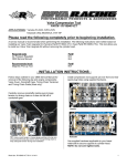
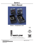
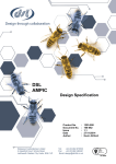
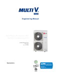
1
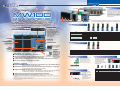
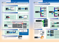
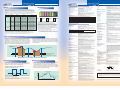
Data Acquisition Unit MW100 MW100 Data Acquisition Unit The MW100 is a scalable, high performance data acquisition/data-logging platform designed for both PC-controlled and stand-alone operation under harsh operating conditions. Bulletin 04M10B01-01E www.yokogawa.com/daq/ System Configuration Standard Configuration Base plate A custom MW100 measuring system is comprised of three elements; the MW100 main module, MX Series input/output modules, and MX150 Series base plate. The system can be bench mounted as-is or DIN rail mounted for rack or panel installations. A DIN rail-mounting bracket is included with the MX150. DIN rail mounting bracket The MW100 is a scalable, high performance data acquisition/data-logging platform designed for both PCcontrolled and stand-alone operation under harsh operating conditions. Open Ethernet connectivity with web-based configuration and data monitoring functions allow MW100 to tim trends with your web handle a wide range of monitoring and historical logging functions. See real time browser from any PC and no special software. A full range of input/output modules handle all of your process inputs with fast measurement speed and high noise immunity for rock-solid performance. Status Display With two input/output modules installed Input/Output modules Input Modules MW100 Main Module This is the data acquisition engine that handles data saving and communications functions. Measured data is saved to CompactFlash (CF) card (sold separately). Up to six input/output modules can be installed on a single base plate. Any combination of available input/output modules can be used. MX110-UNV-H04 Name Universal Input Modules 4-Wire RTD and Resistance Input Module Strain Input Modules CF CF card slot The input/output modules, base plate, and accessories are all the same as those for the MX100 DAQMASTER series (AC adapter is for the MW100 only). Main module 5 V Digital Input Module 24 V Digital Input Module Ethernet port Model MX110-UNV-H04 MX110-UNV-M10 MX110-V4R-M06 MX112-B12-M04 MX112-B35-M04 MX112-NDI-M04 MX115-D05-H10 MX115-D24-H10 MX110-UNV-M10 MX110-V4R-M06 Number of channels Shortest measurement interval 4 10 6 10 ms 100 ms 100 ms 4 100 ms 10 10 10 ms 10 ms MX112-B12-M04 MX112-B35-M04 MX112-NDI-M04 MX115-D05-H10 MX115-D24-H10 Description DC voltage, thermocouple, 3-wire RTD, DI (non-voltage contact, Level (5V logic)). Mixed input allowed. DC voltage, thermocouple, 3-wire RTD, DI (non-voltage contact, Level (5V logic)). Mixed input allowed. DC voltage, 4-wire RTD, 4-wire resistance, DI(non-voltage contact, Level (5V logic)). Mixed input allowed. Built-in bridge resistance of 120 Ω Built-in bridge resistance of 350 Ω For connection with an external bridge head and strain gauge type sensor (NDIS connector) Non-voltage contact, open collector, and Level (5V logic). Mixed input allowed. Level (24 V logic), Vth = 12 V (comes standard) Input/Output Modules The various input/output modules available are of superior insulation. RS-232, RS-422A/485 (optional) START/STOP button With screw terminal option or DC power supply option Web Monitor The MW100’s settings and realtime monitoring of measured values can be implemented with a Web browser (requires a browser with Java VM and Java Script installed.). o✔ In a wide range of temperatures: -20 to 60°C1,2,3,4 o✔ Reinforced insulation: Between input terminal and case5, 3700 Vrms (one minute) or 600 Vrms/VDC (continuous) o✔ A wide variety of network functions: HTTP, FTP, DHCP, SNTP, E-mail, and others. o✔ DC power supply (12 V–28 V) option available. o✔ High speed measurement with a single unit (10 channels/10 ms or 60 channels/100 ms): Shortest measurement interval of 10 ms o✔ Multi-interval: Enables mixing of three different measurement intervals in a single unit (measurement intervals can be set for each module) o✔ Supports CompactFlash (CF) cards6 of up to 2 GB Continuous data acquisition is possible on 60 channels at 100 ms for approximately ten days with a 2-GB card, or for three months on 60 channels at 1 s. o✔ MATH function on the main module available with the /M1 option. o✔ Collective data acquisition on 360 channels (via Modbus with the /M1 option) 2 Output Modules 1. The operating temperature range for the input modules and main module. The operating temperature range of the output modules is -20 to 50°C. 2. Note that the power cord supplied with the main module differs depending on the operating temperature range (see the specifications on page 7). If the operating temperature range specification of the supplied standard power cord does not meet your requirements, we recommend that you select a screw-type terminal rather than the plug type for the main module power inlet, and supply your own power input cable. 3. The operating temperature range of the AC adapter used with DC power supplies is 0 to 40°C. 4. Please consult with a representative for applications involving temperatures below -20°C. 5. The withstand voltage value with the MX110 input module. For the withstand voltage values of other input and output modules, please refer to the specifications for those modules (GS 04M10B01-01E). 6. CF card not included (sold separately). MX120-VAO-M08 MX120-PWM-M08 MX125-MKC-M10 Name Analog Output Module PWM Output Module Digital Output Module Model MX120-VAO-M08 MX120-PWM-M08 MX125-MKC-M10 Number of channels Output update interval 8 8 10 100 ms 100 ms 100 ms Base Plate MX150 Description Allows mixed voltage (±10 V) and current (4-20 mA) output Pulse width modulation output module “A” contact (SPST) Accessories (Removable Terminals) Base plates available for all configurations, from 1 to 6 input/output modules. When used for the MW100, you must replace the attachment with the one that comes standard with the MW100. All input/output terminals are removable except for those of the MX112-NDI-M04. If multiple terminals are prepared ahead of time, no re-wiring is needed between measurements. 772063 Accessories lConnector Covers Connector covers for open slots 772066 772064 772065 Model lAC Adapter (772075) AC adapter for the DC power model. Operating temperature range: 0 to 40°C 772062 772061 772067 772068 772069 772080 Description (M4) terminal block (RJC (reference junction compensation) included). 772061 Screw For use in combination with 772062. Compatible with MX110-UNV-M10, MX115-D05H10, and MX115-D24-H10. cable between input modules and the screw terminal block. 772062 Connection Compatible with MX110-UNV-M10, MX115-D05-H10, and MX115-D24-H10. Plate with clamp terminals (RJC included). 772063 Compatible with MX110-UNV-M10, MX115-D05-H10, and MX115-D24-H10. 772064 772065 772067 772068 772069 Clamp terminals. Compatible with MX110-UNV-H04. Clamp terminals. Compatible with MX120-VAO-M08, MX120-PWM-M08, and MX125-MKC-M10. Plate with clamp terminals. Compatible with MX110-V4R-M06. Plate with clamp terminals (Built-in bridge resistance of 120 Ω). Compatible with MX112-B⫻⫻-M04. Plate with clamp terminals (Built-in bridge resistance of 350 Ω). Compatible with MX112-B⫻⫻-M04. with screw (M3) terminal (RJC included). 772080 Plate Compatible with MX110-UNV-M10, MX115-D05-H10, and MX115-D24-H10. 3 Basic Data Logging This is the basic flow for acquiring measured data. Settings (excluding some communications settings) and real time monitoring of measured data can be performed using a browser (Internet Explorer 5.5 and 6). Advanced Data Logging Multi-Access The MW100 can be connected to multiple PCs at the same time. This allows monitoring and sharing of measured data by multiple users. A login function is included to enable assigning of access rights. Setup Measurement information shared Data Files CF CompactFlash Set up the MW100 from the browser’s screen. Measured data shared Monitor WebDAV client Data Monitor FTP Client Data Settings can be saved and loaded on the main unit. If desired, you can copy the settings from one MW100 onto another via the CF card. Data Acquisition Data <Offline> Monitor Ethernet operation can be controlled either online or offline. <Online> CF card FTP server Ethernet Start/Stop Data Recording Measured data is recorded to the CF card in the MW100. Starting and stopping of the record E-mail* Monitor START/STOP button Start and stop data recording using the START/STOP button on the MW100. * Mail server required. Connect to Other Devices Acquire up to 360 Channels in One System Start and stop data recording using the browser. An optional serial MODBUS RTU interface provides data exchange functions with other devices such as recorders, PLCs and controllers. In this mode, MW100 can serve as expansion I/O or as a data acquisition terminal for another connected device. MW100/M1 You can use a browser for realtime monitoring of measured data. While monitoring, you can also control starting and stopping of the record operation from the browser screen. Start/stop data recording Writing message Output modules can be controlled manually. Server 60 channels Paperless recorder Client 60 channels You can include previouslyregistered messages. You can also display data using bar graphs and meters. As an expansion I/O Server 60 channels You can switch displayed groups. A large data acquisition system of up to 360 channels can be assembled using multiple MW100s and standard MODBUS TCP Ethernet communications. When equipped with the /M1 math option, the MW100 can acquire up to 300 channels of external data from additional MW100 units or other devices such as a PLC using MODBUS TCP communications. This provides a total system capacity of 360 channels (60 built-in measure channels + 300 external). RS-422A/485 Server 60 channels Ethernet Realtime Monitoring DX100/200 with the MATH and serial communication options Remote Data Acquisition RS-485 Server 60 channels MW100 with the MATH and serial Power monitor etc. communication options Please check the specifications of the instruments to be connected before selecting options (such as whether the Modbus function is an option). Drag & drop CF CompactFlash Using WebDAV or FTP, you can easily transfer data from the MW100 to a PC. Time Synchronization Ethernet When the measurement location is located remotely from the data monitoring station, a dial up phone connection can be used for communications. All MW100 web browser-based data monitoring and FTP functions can be used via this connection for remote data acquisition applications. Time server SNTP client SNTP client Router Data Analysis Measured data can be displayed using the Viewer Software (comes standard), enabling waveform display, digital display, or interval arithmetic. Data can be converted to Excel, Lotus, or ASCII format. 4 SNTP server SNTP client Router Screen updating may be slower depending on the communication environment. PSTN line Leased line The MW100 can synchronize its clock to a network time-server using SNTP (Simple Network Time Protocol), allowing any number of MW100s in a system to have precisely matched time. SNTP client Ethernet Data Transfer MW100 with the serial communication option As a data acquisition terminal Server 60 channels Serial MODBUS RTU communications (RS232 or RS-422A/485) can be ordered as a separate option with the same capability. Measured data saved to the CF card in the MW100 can be transferred to the PC either online or offline. Data Both SNTP Server and Client modes are supported. In Server mode, one MW100 can acquire time data from a server using Client mode. It can then serve time data in Server mode to other MW100s that function as Clients. Clock synchronization functions are allowed only when the measurement interval within the unit is two seconds or longer. 5 Main Unit Recording Function Specifications Event/Action Function Common Specifications Memory Multi-Interval Operating temperature range1: -20 to 60⬚C (when not using the MX120 or MX125 output modules) -20 to 50⬚C (when using the MX120 or MX125 output modules) Operating humidity range2, 3: 20-80% RH for -20-40⬚C 10-50% RH for 40-50⬚C 5-30% RH for 50-60⬚C Rated power supply voltage: AC power supply: 100-240 VAC (with or without AC adapter) DC power supply: 12-28 VDC Range of operating power supply voltage: AC power supply: 90-250 VAC (with or without AC adapter) DC power supply: 10-32 VDC Power supply frequency: 50 Hz ⫾2%, 60 Hz ⫾2% (AC power supply) Power consumption: Approximately 70 VA max when six modules are used (using AC power supply) Approximately 35 VA max when six modules are used (using DC power supply) Approximately 70 VA max when six modules are used (using DC power supply and AC adapter) Weight: Approximately 4.3 kg (total weight with six modules installed) Supported Standards: CSA, UL (CSA, NRTL/C), CE, C-Tick 1. Not including operating temperature range specification of accessory AC power cord and AC adapter. The operating temperature range specifications by AC power supply cord and AC adapter are as shown below. Select a CF card appropriate for the required data recording time. See the table below for the approximate time’s worth of data that can be recorded for each size of card. For example, when recording ten channels of data at a 10 ms measurement interval, the approximate amount of data that can be recorded to a 128-MB CF card is 8.8 hours worth. On the MW100, measured data is recorded to the CF card via an SRAM. The SRAM is backed up with a battery (for approximately ten years), ensuring that even in the event of a power failure, data prior to the failure is not lost. Recording channels 10 channels 20 channels 60 channels Measurement interval 10 ms1 100 ms 500 ms 1s 2s 5s 50 ms2 100 ms 500 ms 1s 2s 5s 100 ms 500 ms 1s 2s 5s 128 MB 512 MB 1 GB Approx. 8.8 hours Approx. 1.4 days Approx. 2.8 days Approx. 3.7 days Approx. 14.8 days Approx. 28.9 days Approx. 18.5 days Approx. 74.0 days Approx. 144 days Approx. 37.0 days Approx. 148 days Approx. 289 days Approx. 578 days (1.5 years) Approx. 74.0 days Approx. 296 days Approx. 185 days Approx. 740 days Approx. 1446 days (3.9 years) Approx. 22.2 hours Approx. 3.7 days Approx. 7.2 days Approx. 1.8 days Approx. 7.4 days Approx. 14.4 days Approx. 9.2 days Approx. 37.0 days Approx. 72.3 days Approx. 18.5 days Approx. 74.0 days Approx. 144 days Approx. 37.0 days Approx. 148 days Approx. 289 days Approx. 92.5 days Approx. 370 days (1year) Approx. 723 days ( 1.9 years) Approx. 14.8 hours Approx. 2.4 days Approx. 4.8 days Approx. 3.0 days Approx. 12.3 days Approx. 24.1 days Approx. 6.1 days Approx. 24.6 days Approx. 48.2 days Approx. 12.3 days Approx. 49.3 days Approx. 96.4 days Approx. 30.8 days Approx. 123 days Approx. 241 days Ex: Measurement interval: 500 m Measurement interval: 100 ms Measurement interval: 10 s The MW100 enables mixing of three different measurement intervals in a single unit. Measurement intervals can be set for each individual module. This allows you to measure various items under test at the most appropriate measurement intervals. Also, you can set data recording conditions1 for each measurement interval, thereby using the available space on the CF card as efficiently as possible. Suffix code in the Model name (see page 8) Standard applicable to included power cord Operating temperature -1D UL/CSA -20 to 60⬚C -1F VDE -15 to 60⬚C -1R SAA -15 to 60⬚C -1Q BS -15 to 60⬚C -1H GB (CCC) -15 to 60⬚C The operating temperature range of the AC adapter is 0 to 40⬚C. 2. The operating humidity range of the AC adapter is 20-80% RH at 0-40⬚C. (no condensation) 3. NO condensation Model-Specific Specifications ●Main Module (MW100) Basic Functions Main functions: 1. At a measurement interval of 10 ms, the maximum number of channels that can be measured is 10. Eleven or more channels cannot be measured at a measurement interval of 10 ms. 2. At a measurement interval of 50 ms, the maximum number of channels that can be measured is 30. Thirty-one or more channels cannot be measured at a measurement interval of 50 ms. Control of the power supply and I/O modules, communications with the PC, and storage of data on the CF card. 10/50/100/200/500 ms, or 1/2/5/10/20/30/60 sec Note that the configurable measurement intervals differ depending on the modules. Also, the following limitations apply to the measurement interval and number of measurement channels. Measurement interval: Measurement Interval 1. Single: Save a file up to the specified size then stop recording. Full Stop: Stop recording once the CF card is full. Rotate: When the capacity of the CF card has been exceeded, the oldest files are deleted to free up space, then recording continues. Storage capacity in terms of time by CF card size and numbers of channels Max number of measurement channels 10ms 10 10 ms and 50 ms mixed 10 50 ms Multi-interval (measurement groups): Synchronization between modules: Synchronization between channels: Filter function: Operation after failure recovery: Trigger and Data Thinning Functions The MW100 is equipped with built-in trigger functions. Data recording can be started based on alarm values, time, external contact input, or other parameters. Once recording is started, it can be set to progress continuously or according to a specified data length. When specifying a data length, a pre-trigger can also be set. The MW100 also provides a data thinning function. Overview: •Normal Operating Conditions Notes Modules whose measurement interval is not set to 10 ms or 50 ms can be set to 100 ms or higher. 30 Three measurement intervals can be set for each module within a unit. Synchronized within the same measurement interval (within the same unit) Synchronized between channels in the same module for the MX110-UNVH04 and the MX115-Dxx-H10. Channels within the MX110-UNV-M10, MX110-V4R-M06, and M112 input modules are asynchronous due to the scanner type. First-order lag filter can be set on each channel. After recovery from a power failure, the operation before the failure is continued. Input MATH Function (Functions Available from the Main Module without the MATH Option (/M1)): Portions of measured data can be omitted at regular intervals during measurement (minimum of four seconds) before data is recorded. Using the trigger and data thinning functions together provides "coarse" recording of general data and "fine" recording of abnormal data. Hysteresis: Number of relay outputs: Output mode: Alarm ACK: Alarm update interval: Output interval: Output interval: Measurement Interval Data Recording Using the Trigger and Data Thinning Functions Pulse Integration (/M1 Option) This function is included with the MATH (/M1) option. You can easily perform pulse integration using the MX115 Digital Input Module or the MX110 Universal Input Module. Example of pulses that can be integrated at a measurement interval of 10 ms: Broken Line Chart Output (/M1 Option) This function is included with the MATH (/M1) option. Patterns can be output from the analog output and PWM output modules (MX120) by inputting the coordinates of the pattern you wish to generate. In the pattern output shown in the figure below, points (X1,Y1) through (X10,Y10) are input in advance, and the output is generated accordingly. Alarm output, communication command output (output in response to digital output requests from the PC), error output, and other outputs 100 ms (not synchronized with the measurement interval) Communication command output (output in response to analog output requests from the PC), transmission output, error output, and other outputs 100 ms (not synchronized with the measurement interval) 12.5 ms 12.5 ms For accurate pulse detection, the pulse width must be longer than the measurement interval. 6 For pulse integration at a measurement interval of 10 ms/50 ms, aside from the module performing the pulse integration, input modules of measuring interval 100 ms or more must be set up for measurement in the same unit. Output value Y (X6, Y6) (X7, Y7) (X4, Y4) (X5, Y5) (X9, Y9) (X2, Y2) (X3, Y3) (X8, Y8) (X1, Y1) (X10, Y10) X Time (set in units seconds) Number of MATH channels Number of channels for computation: 60 (can also be used as communication input channels) Number of channels for communication input: 240 Computations: Basic math functions (+, -, x, ⫼, power) Relational operators (>, ⭌, =, ⬉, <, ⫽) Logical operators (AND, OR, XOR, NOT) Arithmetic operators (SQR, ABS, LOG, EXP) TLOG computations (max, min, max-min, average, integration, pulse integration) CLOG computations (max, min, max-min, average) Conditional expressions ([EXPR1?EXPR2:EXPR3]) MATH reference channels: The following types of channels can be incorporated into expressions. Measurement channels, MATH channels, communication input channels, flag input channels, MATH constants, and broken-line input channels. Characters used in expressions: Up to 120 per channel For communication input channels, a maximum of 8 characters can be used per channel. MATH constants: 60 Flag input channels: 60 Flag value (0 or 1) can be substituted in computational expressions. Varies according to the action of the Event/Action function. Broken-line input channels: 3 The output from the MX120 output modules can be executed according to the broken lines specified on these channels. Computation alarm function: Four levels per channel. Upper limit and lower limit types only. MATH interval: Assigned to one of the measurement groups (of measurement interval 100 ms or more) Recording Function Specifications Main functions: Measured values, computed values, thinned values, setting values, data acquisition log, and alarm summary can be saved to CF card. CF card Type II x 1 slot (Type I can also be used) Maximum allowable card size: 2 GB Internal backup memory: Uses the main unit’s internal backup memory (SRAM) to save data to CF card without loss before a power failure. Saving/Loading settings: Saves all settings to CF card. Loads settings from the CF card. •Measured and Computed Value Recording Function: Record start/stop: Starts and stops recording to CF card according to the START/STOP key, Event/Action function, or communication commands. Recording operation: Measured values and computed values are recorded in separate files on the CF card. If measured values are divided by group, a separate file is created and saved on the CF card for each group. Measurement groups: Measurement channels can be divided into up to 3 groups by module. Recording mode: Select a record complete action for each measurement group of Single, Full stop, or Rotate. Trigger function: Included. Pre-triggers can also be set. Recording interval: Set the recording interval for each measurement group as an integer multiple (multiples restricted) of the measurement interval. File name: Generated automatically in sequence using the date and time (cannot be specified by the user). Recording channels: Recording can be turned ON/OFF independently on each channel. Writing message: During execution of the recording action, a message synchronized with the recorded data can be included in the file. Five messages of up to 15 characters each are available for including in a single file, up to ten messages per file. •Thinned Value Recording Function Record start/stop: Executed simultaneously upon recording of the measured values and computed values. No trigger functions are available. Recording Mode: Select a record stop action of Single, Full stop, or Rotate. Thinning time: Data recording is set for 1 per thinning time (the thinning time restricted). File name: Generated automatically in sequence using the date and time (cannot be specified by the user). Recording channels: Can be specified for each channel (settings for recording of measured and computed values are set separately) During execution of the recording action, a message synchroniz ed with the Writing message: recorded data can be included in the file. Five messages of up to 15 characters each are available for writing to a single file, up to ten messages per file. Supported external media: Communication services: Login function: DHCP function: SNTP function Client function: Server function: Mail function: Ethernet interface comes standard with the Main Module (MW100). Also, either an RS-232 or RS-422A/485 interface can be added to the main module as an option. Ethernet (10Base-T) FTP, SMTP, SNTP, DHCP, DNS, HTTP, ModbusTCP, and a dedicated MW100 protocol. Send/receive setting values, send measured values and computed values, maintenance/diagnosis of the communication connection, and others. Use when accessing a setting/measurement server, maintenance/diagnostic server, FTP server, or HTTP server. Up to 10 users can be registered. The IP address is automatically obtained from the DHCP server Gets time information from the specified serer such as when power is turned ON and when recording starts. Supplies time information to any MW100s connected to the network. Sends timing information via e-mail including the time of alarm activation/ release, specified time, file creation time, time at which free memory space drops below specified amount, time power turned ON, and time errors occur. FTP function Client function: Files from the CF card containing measured values, computed values, and thinned values are automatically sent to the FTP server. A primary and secondary destination server can be specified. Server function: File transfers from the CF card, directory manipulation within the CF card, deletion of files from the CF card, and other functions can be carried out through requests from the computer. HTTP function: Enables entry of settings on the MW100 and real time monitoring of measured and computed values using a Web browser, and file acquisition on the CF card using WebDAV, and other functions. Supported OS and browser: Windows 2000/XP, Internet Explorer 5.5 and 6.0 •RS-232 Interface Specifications (/C2 Option) Connection method: Point-to-point Baud rate: Select 1200, 2400, 4800, 9600, 19200, 38400, 57600, or 115200 bps Protocol: Dedicated protocol and Modbus/RTU Communication services: Send/receive setting values, send measured and computed values. •RS-422A/485 Interface (/C3 Option) Connection method: Multidrop, 4-wire 1:32, 2-wire 1:31 Baud rate: Select 1200, 2400, 4800, 9600, 19200, 38400, 57600, or 115200 bps Protocol: Dedicated protocol and Modbus/RTU Communication services: Send/receive setting values, send measured and computed values. •Communication input function: All settings on the main unit other than dip switch and power switch operation can be performed with communication commands. •Communication output function: •Modbus Function Communication media: For Ethernet Transmission mode: For RS-232 and RS-422A/485 Transmission mode: Supported functions: Using communication commands, the most recent measured data, the most recent computed values, and other information can be output. Ethernet RS-232 RS-422A/485 Modbus/TCP sever, client /M1 option must be selected to use the Modbus/TCP client function. Modbus/RTU slave, master /M1 option must be selected to use the Modbus/TCP master function. Reading from registers, and writing to registers. Other Specifications Power consumption: Common-mode voltage: Insulation resistance: Withstand voltage: AC power: MATH Function Specifications (/M1 Option) l: Data recorded by triggering l: Data recorded by the data thinning function •Ethernet Interface Specifications Interface: Main protocols: Measurement and MATH channels Four levels per channel Upper limit, lower limit, differential upper limit, differential lower limit, rate of change upper limit, rate of change lower limit. Differential upper limit and differential lower limit only available for differential input measurement channels. Only upper limit and lower limit alarms can be set on MATH channels. Can be set for each channel (however, fixed at 0 for MATH channels and with rate of change alarms) 1 to 60 points depending on the number of mounted MX125 Digital Output Modules. Excitation/non-excitation, AND/OR, Hold/Non-hold, reflash alarm If set to Hold using the alarm status or relay output Hold/Non-hold function, the hold status is cleared. 100 ms (not synchronized with the measurement interval) Analog Output Function (Available Only When the MX120-VAO-M08 Analog Output Module Is Installed) Measured value Overview: Tags: Internal clock accuracy: Summer/winter time: Digital Output Function (Available Only When the MX125 Digital Output Module Is Installed) Trigger detection per alarm value Actions: By linking the Event and Action in the setting items, you can control the operations of the main unit. Digital input information, alarm occurrence, relay output, internal timer time up, match time, user function key, and others. Recording start/stop, activate trigger, MATH start/stop/reset/clear, reset timer, alarm ACK, flag input, write message, and others. Communication Specifications Differential computation between channels, linear scaling computation, remote RJC, initial balance (with the MX112 Strain Module) Alarm Functions Channels: Number of alarms: Alarm types: Events: DC power: Weight: Select channel or tag display for all channels together. ⫾100 ppm The time on the internal clock is updated on the specified month, week, day of the week and time. Approximately 8 W for the main module alone. 150 VACrms (50/60 Hz) between DC power supply terminal and earth terminal. 20 MΩ or more (500 VDC) between power supply terminal and earth terminal 1500 VACrms (50/60 Hz) between power supply terminal and earth terminal for 1 minute. 1000 VACrms (50/60 Hz) between power supply terminal and earth terminal for 1 minute. Approximately 1 kg (MW100 main module alone) Input/Output modules •Universal Input Modules (MX110) Measurement range: DC voltage1: Thermocouple2: 20/60/60 (high resolution)/200 mV, 1/2/6/6 (high resolution)/20/100 V R, S, B, K, E, J, T, L, U, N, W, KpvsAu7Fe, PLATINEL, PR40-20, NiNiMo, WRe3-25, W/WRe26, Type-N (AWG14), TXK GOST Pt50, Pt100, Pt100 (high resolution), JPt100, JPt100 (high resolution), Pt25 (JPt100⫻1/4), Ni100 SAMA, Ni100 DIN, Ni120, Cu10 GE, Cu10 GE (high resolution), Cu10 L&N, Cu10 L&N (high resolution), Cu10 WEED, Cu10 WEED (high resolution), Cu10 BAILEY, Cu10 BAILEY (high resolution), Cu10 at 20⬚C alpha=0.00392, Cu10 at 20⬚C alpha=0.00393, Cu25 at 0⬚C alpha=0.00425, Cu53 at 0⬚C alpha=0.00426035, Cu100 at 0⬚C alpha=0.00425, J263B, Pt100 GOST, Cu100 GOST, Cu50 GOST, Cu10 GOST RTD3: Pt100 (high noise resistance), JPt100 (high noise resistance) RTD4: Pt500, Pt1000 DI1: Non-voltage contact, level (5V logic) Resistance4: 20/200/2k ⍀ 1: Specifications Common to the MX110-UNV-H04, MX110-UNV-M10, and MX110-V4R-M06 2: Specifications Common to the MX110-UNV-H04 and MX110-UNV-M10 3: Specifications Specific to the MX110-UNV-H04 4: Specifications Specific to the MX110-V4R-M06 •Strain Input Modules (MX112) Types of measurement: Strain gauge or strain gauge sensor (static strain) Gauge connection method: Single-gauge (2 or 3 wire), opposed-side two-gauge, adjacent-side twogauge or four-gauge Applicable gauge resistance: 100 to 1000 ⍀. Built-in resistance of 120 ⍀ for -B12, and 350 ⍀ for -B35. Bridge voltage: 2 VDC fixed (accurate to ⫾5%) Applicable gauge factor: 2.0 fixed, gauge factor correction possible with scaling function Measurement ranges: 2000/20000/200000 strain •Digital Input Modules (MX115) Non-voltage contact, level (5 V logic), open collector Types of input1: Type of input2: Level (24 V logic) 1: Specifications Specific to the MX115-D05-H10 2: Specifications Specific to the MX115-D24-H10 •Analog Output Module (MX120-VAO-M08) Main functions: Output of set and computed values, retransmission of measured and computed values, and other functions. Rated output range: Voltage: -10 to 10 V, current: 0 to 20 mA, sourcing (4 to 20 mA is output at 1 to 5 V output) External power supply (used for current output): 24 V ⫾10% and current capacity of 250 mA or more. •PWM Output Module (MX120-PWM-M08) Main functions: Output of set and computed values, retransmission of measured and computed values, and other functions. Output waveform: Outputs a pulse width. External power supply required. RTD1: Pulse width Pulse interval Depends on external power supply voltage Pulse interval: External power supply: Output capacity: 1 ms to 300 s 4 V to 28 V Max 1 A/channel, however, the total of one module is 4 A or less Note: If temperature (thermocouple), resistance, or strain measurements are taken by the MX110 or MX112 at an integral time of 1.67 ms, the measured values may be susceptible to inaccuracies due to power supply frequency noise. If this is the case, set the integral time to 16.67 ms or longer (for a power supply frequency of 60 Hz), or 20 ms or longer (for a power supply frequency of 50 Hz). On DAQMASTER, the integral time is automatically set when selecting the measurement interval, but the relationship between the integral time and the measurement interval differs depending on the modules. If measured values are inconsistent, consult the user’s manual for guidance on how to select a measurement interval that will yield a sufficient integral time. See GS 04M10B01-01E for detailed specifications of main module and I/O modules other than the above. 7 Accessories Model Name Model Description 772065 1,2 -1 -2 -3 Power supply inlet and D power supply cord F R Q H W Options /C2 /C3 /M1 Main module (with MW100 Viewer Software) English (with English user’s manual)3 100 VAC–240 VAC 12 VDC–28 VDC, with AC adapter4 12 VDC–28 VDC, without AC adapter5 AC power: 3-pin power inlet with UL/CSA cable DC power: Screw terminal, UL/CSA cable for AC adapter AC power: 3-pin power inlet with VDE cable DC power: Screw terminal, VDE cable for AC adapter AC power: 3-pin power inlet with SAA cable DC power: Screw terminal, SAA cable for AC adapter AC power: 3-pin power inlet with BS cable DC power: Screw terminal, BS cable for AC adapter AC power: 3-pin power inlet with GB (CCC) cable DC power: Screw terminal, GB (CCC) cable for AC adapter Screw terminal, power supply cord not included4,5 RS-232 communication interface6,7 RS-422A/485 communication interface6,7 MATH function7,8 Note: The 772065 model is applicable only to the MX120-VAO-M08 (Eight-Channel Medium-Speed Analog Output Module), the MX120PWM-M08 (Eight-Channel Medium-Speed PWM Output Module) or the MX125-MKC-M10 (Ten-Channel Medium-Speed Digital output Module). Model 772066 Model 772067 Suffix Code Model Option Code -UNV -V4R -H04 Measurement interval, number -M06 of channels -M10 Option /NC Model 772068 Model 772069 Model 772080 -B12 -B35 -NDI Measurement interval, number of channels -M04 Suffix Code Model Description -D05 -D24 Measurement interval, -H10 number of channels Option Description Strain input module Built-in bridge resistance: 120 Ω Built-in bridge resistance: 350 Ω For connection to external bridge head and strain gauge type sensor (NDIS connector) 4 channels, Medium speed (Shortest measurement interval: 100 ms) Option Code MX115 Input type Description Digital input module Non-voltage contact, 5 V logic, open collector 24 V logic 10 channels, high speed (shortest measurement interval: 10 ms) /NC Model 772075 Power supply cord 438920 438921 438922 415920 415921 415922 772090 772091 772092 772093 772094 Model Model Model MX150 Base type Specifications 250 Ω ± 0.1% 100 Ω ± 0.1% 010 Ω ± 0.1% 250 Ω ± 0.1% 100 Ω ± 0.1% 010 Ω ± 0.1% Description Shunt Resistance (for clamp terminals) Shunt Resistance (for screw (M4) terminals) Adapter for CompactFlash Memory Card 128 MB1 256 MB1 512 MB1 001 GB1 CompactFlash Memory Card (CF card only) Model Description MW100 Viewer Software Description Analog output module Voltage/Current output (allows mixed voltage and current output) Pulse width modulation output 8 channels, output update cycle: 100 ms Suffix Code MX125 Output type -MKC Output update cycle, number of channels -M10 Description AC adapter Cable for UL/CSA Cable for VDE Cable for SAA Cable for BS Cable for GB (CCC) Application Software The plate with clamp terminals is not attached. Suffix Code -VAO -PWM Measurement interval, number of channels -M08 Suffix Code -D -F -R -Q -H 1. Operating temperature range: -40 to 85°C MW180 MX120 Output type Description Screw (M3) terminal plate (RJC included) Note 1) The 772080 is applicable only to the MX110-UNV-M10 (Ten-channel Medium Speed Universal Input Module), the MX115-D05-H10 (Ten-channel High Speed 5 V DI Module), and the MX115-D24-H10 (Ten-channel High Speed 24 V DI Module). Note 2) Terminal cover included Note 3) b terminals for RTD are common (2 terminals) Model MX112 Input type Description Plate with clamp terminals (Built-in bridge resistance of 350 Ω) Note: The 772069 is applicable only to the MX112-B35-M04 (Four-Channel Medium Speed Strain Input Module, 350 Ω), or the MX112-B12M04 (Four-Channel Medium Speed Strain Input Module, 120 Ω). Analog input module DCV/TC/DI/3-wire RTD1 DCV/DI/4-wire RTD/4-wire resistance1 4 channels, high speed (shortest measurement interval: 10 ms) 6 channels, medium speed (shortest measurement interval: 100 ms)1 10 channels, medium speed (shortest measurement interval: 100 ms)2 The plate with clamp terminals is not attached.2 Suffix Code Description Plate with clamp terminals (Built-in bridge resistance of 120 Ω) Note: The 772068 is applicable only to the MX112-B12-M04 (Four-Channel Medium Speed Strain Input Module, 120 Ω), or the MX112-B35M04 (Four-Channel Medium Speed Strain Input Module, 350 Ω). 1. “-M06” must be specified when “-V4R” is specified. “-M06” can not be specified when “-UNV” is specified. 2. “/NC” can be specified only when “-M10” is specified. Model Description Plate with clamp terminals Note: The 772067 model is applicable only to the MX110-V4R-M06 (Six-Channel Medium-Speed 4-Wire RTD and Resistance Input Module). 1. CF card does not come standard. 2. Modbus/TCP server function comes standard. 3. Displays Celsius or Fahrenheit, Winter/Summer time can be set. 4. “W” cannot be selected with “-2” 5. “-3” can only be selected with “W” 6. “/C2” and “/C3” may not be selected together 7. “/C2” or “/C3” must be selected to use the Modbus/RTU slave function. Also, “/M1” must be selected for use of the Modbus/RTU master function. 8. “/M1” must be selected to use the Modbus/TCP client function. MX110 Input type Description Connector cover for base plate Exterior Dimensions Unit : mm Description Digital output module “A” contact (SPST) 10 channels, output update cycle: 100 ms Suffix Code Description L 158.6 Base plate For connection with one main module and one input/output module For connection with one main module and two input/output modules For connection with one main module and three input/output modules For connection with one main module and four input/output modules For connection with one main module and five input/output modules For connection with one main module and six input/output modules -1 -2 -3 -4 -5 -6 105 MEASURE ALARM RECORD ETHERNET STOP USER 1 USER 2 100 - 240V AC ON OFF L Ten-Channel Screw (M4) Terminal Block (RJC included) Note: The 772061 model is applicable only to the MX110-UNV-M10 (Ten-Channel Medium-Speed Universal Input Module), the MX115-D05H10 (Ten-Channel High-Speed 5 V Digital Input Module) or the MX115-D24-H10 (Ten-Channel High-Speed 24 V Digital Input Module). Suffix Code Description Cable for connection between the input module and the screw terminal block 50 cm cable 100 cm cable Note: The 772062 model is applicable only between the MX110-UNV-M10 (Ten-Channel Medium-Speed Universal Input Module) and the Screw Terminal Block (772061), between the MX115-D05-H10 (Ten-Channel High-Speed 5 V Digital Input Module) and the Screw Terminal Block (772061) or between the MX115-D24-H10 (Ten-Channel High-Speed 24 V Digital Input Module) and the Screw Terminal Block (772061). Model 772063 Description Model N 1 Description Clamp terminals Note: The 772064 model is applicable only to the MX110-UNV-H04 (Four-Channel High-Speed Universal Input Module). 3 4 5 6 163 165 223 281 339 397 455 See GS 04M10B01-01E for the dimensions of the 772061 and the dimension for installation in upper and lower directions using the DIN rail. DAQMASTER is a registered trademark of Yokogawa Electric Corporation. TCP/IP software of this product and documents on TCP/IP software were developed/created by Yokogawa Electric Corporation on the basis of BSD Networking Software (Release 1) licensed from University of California. Microsoft, MS, Windows, and Excel are registered trademarks of Microsoft Corporation in the United States. Lotus and 1-2-3 are registered trademarks of Lotus Development Corporation. Ethernet is a registered trademark of XEROX Corporation. Java and Java-related trademarks are trademarks or registered trademarks of Sun Microsystems, Inc. in the United States and/or other countries. All other company and product names mentioned here are trademarks or registered trademarks of their respective companies. ● Before operating the product, read the user’s manual thoroughly for proper and safe operation. ● If this product is for use with a system requiring safeguards that directly involve personnel safety, please contact the Yokogawa sales offices. ● This product is not constructed to be explosion-proof. YOKOGAWA ELECTRIC CORPORATION Network Solutions Business Div./Phone: (81)-422-52-7179, Fax: (81)-422-52-6793 E-mail: [email protected] YOKOGAWA CORPORATION OF AMERICA YOKOGAWA EUROPE B.V. YOKOGAWA ENGINEERING ASIA PTE. LTD. 2 NOTICE Plate with clamp terminals (RJC included) Note: The 772063 model is applicable only to the MX110-UNV-M10 (Ten-Channel Medium-Speed Universal Input Module), the MX115-D05H10 (Ten-Channel High-Speed 5 V Digital Input Module) or the MX115-D24-H10 (Ten-Channel High-Speed 24 V Digital Input Module). 772064 L 70VA MAX 50 / 60Hz 156.6 Description Model ON POWER TERMN Number of equipped input/output modules Model 772062 Cable length -050 -100 SW 1 2 3 4 5 6 7 8 10BASE - T START SERIAL COMM 772061 DATA ACQUISITION UNIT MATH SERIAL RD FG SG RXB RXA TXB TXA Accessories DIN rail MW100 -E Language Power supply voltage Description Clamp terminals (31) Model Option Code 131 Suffix Code Phone: (1)-770-253-7000, Fax: (1)-770-251-2088 Phone: (31)-33-4641806, Fax: (31)-33-4641807 Phone: (65)-62419933, Fax: (65)-62412606 Subject to change without notice. [Ed : 01/b] Copyright ©2005 Printed in Japan, 505(KP) RS-14E