1
IlllllllllllllllllllllIlllllllll|||l|IllllIllllllllllllllllllllllllllllllll
.
USOO5092834A
UIllted States Patent [19]
[11] Patent Number:
Bradshaw et a1.
[45]
[54] [APPARATUS AND METHOD FOR THE
Date of Patent:
4,861,520 8/1989 Van’t Hooft et a1. ............ .. 252/644
4,881,937 11/1989 Van’t Hooft et a1. ................ .. 600/3
4,881,938 11/1989
TREATMENT OF CANCER
FOREIGN PATENT DOCUMENTS
857992
Iridium Source,” published by Nucletron Corporation.
[21] Appl. No.: 596,928
A document entitled, “MicroSelectron IDR/MDR
192Ir 137Cs,” published by Nucletron Trading B.V.
Oct. 12, 1990
A document entitled, “Gammamed IIi System Dr.
Int. Cl.5 ............................................. .. A61N 5/00
600/7; 600/3
Sauerwein,” published by Mick Radio-Nuclear Instru
ments, Inc.
Field of Search ...................................... .. 600/3, 7
References Cited
U.S. PATENT DOCUMENTS
4/1930 Failla .
4/1934 Burgett et a1. ........................ .. 219/8
Wappler
..... .. 29/34
2,429,438 10/ 1947 Wappler
128/ 1.2
2,546,761
6/1943
3/1951
Loftus ..... ..
128/1.2
2,798,164 7/1957 Unterrnyer
2,904,272 9/1959
3,060,924 10/1962
3,438,365
3,485,234
3,612,058 10/1971
Barrett ........................ .. 242/54
Rush ................................ .. l28/1.2
Stevens
. . . . . .. . .
6/1972 Sauerwein et a1. ..
3,674,006
7/ 1972
Holmer .......... ..
3,749,086
7/1973
Kline et al. .... ..
3,861,380
l/l975 Chassagne et a1. ..
3,924,632 12/1975
Cook .............. ..
4,096,862
6/1978
DeLuca ...... ..
4,150,298
4/ 1979 Brault et al. .
4,190,461
2/1980
4,425,919
1/1984 Alston, Jr. et a1. ..
Hedger
.. . .. ... .. ..
4,538,622 9/1985 Samson et a1.
4,554,929 11/1985 Samson et a1.
4/1986
Tokita et a1. . . . . .
4,631,415 12/1986 Sauerwein et a1. ..
4,692,628 9/ 1987 Sauerwein et a1. .
4,733,653
3/1988
128/1.2
. . . . . ..
Ackerman ...... ..
3,669,093
4,584,991
250/106
4/1969 Packer et al. .
12/1969
(List continued on next page.)
Primary Examiner-Kyle L. Howell
1,954,868 4/1934 Failla et a1.
2,322,902
United Kingdom .
A one-page document entitled, “MicroSelectron-HDR
Houston, Tex.
1,753,287
1,953,915
l/196l
OTHER PUBLICATIONS
[73] Assignee: Omnitron International, Inc.,
[56]
Van’tI-looft .......... ..
4,969,863
5,030,194 11/1990
7/1991 Van’t Hooft et
..........................
al. ..
.. 600/3
[75] Inventors: Anthony J. Bradshaw, Missouri City;
Richard T. Thornton, League City,
both of Tex.; Michael H. Hayman,
New Orleans, La.
[51]
Mar. 3, 1992
4,819,618 4/1989 Liprie .................................... .. 600/7
REMOTE HANDLING OF HIGHLY
RADIOACTIVE SOURCES IN THE
[22] Filed:
5,092,834
128/2
128/348
128/l.1
..
l28/1.2
ZAssistant Examiner—Scott R. Akers
Attorney, Agent, or Firm-Fitch, Even, Tabin &
Flannery
~ [57]
ABSTRACT
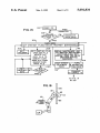
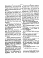
Remote controlled afterloader apparatus and method
positions high activity radioactive sources through a
catheter within a human body for treatment of cancer
ous tissue. The afterloader includes an operating con
sole and a remotely located computer controlled wire
driver. The wire driver includes active and dummy
' source wires and channels for the storage of such wires.
Stepper motors precisely position the wires in response
to computer control and data from wire position encod
ers. An emergency DC motor retraction system pro
vides a high degree of safety against system malfunc
.
tion. Timing arrangements are included for timing pa
. . . . . . ..
134/1
128/658
128/772
128/772
. . . .. 128/1.l
250/497.1
250/497 1
Leung et al. ....................... .. 128/1.2
tient treatment duration and emergency wire retraction
' time. A turret is provided with safety locking and cross
checking systems to permit use of multiple catheters.
Treatment pro?les are conducted from the maximum
treatment position whereby only tension or retraction
, forces are used to position the active wire.
2 Claims, 8 Drawing Sheets
5,092,834
Page 2
OTHER PUBLICATIONS
Two-page document entitled, “Iridium 192 Wires,”
published by Syncor International Corporation.
Document entitled, “MICRO-SELECTRON-HDR,
Ir, 192——Remote Afterloading System User Manual”.
Document entitled, “MICRO-SELECTRON-HDR,
Ir—192—Remote Afterloading System User Reference
Four-page document entitled, “Interstitial Accesso
Guide".
ries”, published by Syncor International Corporation.
Two-page document entitled, “Interstitial Therapy
Two page document entitled, “Afterloading Systems
and Interstitial Applicators Remote Afterloading Sys
Price List”, published in May, 1984, by Syncor Interna
tems”, taken from PRINCIPLES AND PRACTICE
OF RADIATION ONCOLOGY.
tional Corporation.
US. Patent
Mar. 3, 1992
Sheet 1 of 8
1?.
CONTROL
'I
{20
5,092,834
LE
CUQTROL ,v
I
CONSOLE
'3
I
“'0
wIRE
‘4A’ DRIvER
'
1V1i
,
?
I--
CONTROL/PERSONNEL
{
RooM
l
o- -------- —
I8
TREATMENT
ROOM
IO
(28
24
,/
PRINTER
I
I
MONITOR
30
DISK
-
DRIvE
KEY
OFF
UNINTERRUPTIBLE
POWER SUPPLY (UPS)
22
ON
(32
COMPUTER
>_—
220
26 3
KEYBOARD
To REMOTE
WIRE DRIVER
3’5
HORN
:L
I22
C42
O
O O—-
REsET
l.
STOP
34
\
/
/
\
36
\
/
/
\
3a
\
/
RC5 RC9 ‘~95
\
40
44
\
/
/
\
O
ERROR
SAFE
TREATMENT TREAT
ROOM DOOR
OPEN
ARMED
US. Patent
0
WM]
Mar. 3, 1992
Sheet 2 0f 8
5,092,834
US. Patent
Mar. 3, 1992
Sheet 3 of8
5,092,834
FIG.4
O
O
F|G.7
I29
M5
6 66
V‘Cms
us
0
\
H6
0
H2
A
I
00
“5
I08
o
n94
OO
mm
FIG.6
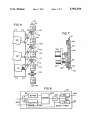
60!
603
b BUFFER
j
commas
T
an
SW
COUNTER
CLEAR
6|2
§607
F",-
TIMER
[
GIOJ
[
6m
1602
TIMER
SANITY TIMER
(
613
(
US. Patent
Mar. 3, 1992
Sheet 4 of 8
5,092,834
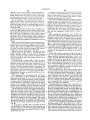
FIG. 5
s52
L/
TuRRET
LOCKED
CATHETER
PRESENT
32
I68
v
20_ I_‘ l
r I3
~@'—~
WIRE DRIVER
CONTROL
SANITY
4"; A
POWER
TIMER
N
SUPPLY
409
(44'
419
ALARM
1
420
RETRACT
TIMER
42|
I (440
|
AL
6l3 i442
Mm em? I r429
-——-+
DOOR OPEN
RESET
OVER RUN
FAULT
i426
CONTROL
LOGIC
427
J
I26]
"— L99
425
ii.
k NC
TREATMENT
ACTIVE
T|MER
PARK
¢— |Q§
?
DUMMY
PARK
.L
1
T
__@_|||
me ‘I
HOME
SEN soR
T» I90
_
l
T
US. Patent
Mar. 3, 1992
Sheet 5 of 8
5,092,834
US. Patent
5,092,834
Sheet 6 of 8
Mar. 3, 1992
3004-’ POWER ON
FIG. l3
WHEN
i’:
CORRECTED '
FA'L
3047
I
ANNUNCIATE
MAIN MENu
h—-————
r—--» ouIT lPATlENT FILES |ExEcuTE TREATMENT |MAINTENANcE
306} l
ExIT
PROGRAM
r308
EDIT EXISTING FILE
OPEN NEW FILE
DELETE F'LE
COPY “L5 To
MEMORY cARD
l
f3l2
SPECIAL MAINTENANCE AND
CALIBRATION PROCEDURES
ACCESSABLE ONLY WITH
sPEcIAI. CODE FOR usE BY
DMNITRDN sERvIcE
PERSONNEL
READ FILE FROM
M M
Y
AR
PERI? FFLE D
3l6
PRINT PATIENT
TREATMENT
DATA
EDIT
TREATMENT
DATA
3l4
J
TuRN
+ KEYSWITCH
'TREATMENT'
I
I
coMMAND
To CONTROL l3
To FIG. l4
AT an;
s
90
N2
US. Patent
Mar. 3, 1992
Sheet 7 0f 8
5,092,834
FROM
FIG.I3
WHEN CORRECTED
FIG‘ '4
FROM
F1615
ANNUNCW'E
PROBLEMS)
319
m
SEND 0K
AWAIT
CATHETER
COMMAND
s22
REPOSITION
TURRET
CHECK
TURRET
CORRECT
POSlTlON
INCORRECT
E M ER GENCY
STOP
W/ ALARM
SEND 0K
AWA‘T
W325
p05 |T|ON
_
l
POSITION
DWMY
l
N526
N32 7
SEND OK
AWAIT
RETRACT
l
RETRACT
~
"328
1
SE ND OK
AWAIT
FIRST
ACTW E
1
TO FIG. l5
@330
US. Patent‘
Mar. 3, 1992
Sheet 8 of 8
5,092,834
FROM FIG.|4
l
332
EXTEND
ACTIVE WIRE
TO FARTHEST
TREATMENT
POSITION
[ass
EMERGENCY
STOP
W/ALARM
3421
RETRACT To
NExT POSITION
TIM‘NG
COMPLETE
AWAiT
@339
340
FULL
RETRACT
N34‘
AWAlTT
A’ ‘342
NEXT
COMMAND
REATMENT
cHmNEL _?
1-0
FIG. l4
1
5,092,834
APPARATUS AND METHOD FOR THE REMOTE
HANDLING OF HIGHLY RADIOACTIVE
SOURCES IN THE TREATMENT OF CANCER
2
of the intense radiation associated with high activity
sources, real-time, hand-guided source placement by
the treating physician is precluded. The source, there
fore, is inserted through a tube, a needle, or catheter
previously surgically positioned in the patient.
BACKGROUND OF THE INVENTION
The present invention relates generally to methods
and apparatus for the handling of high activity radioac
tive sources in the treatment of cancerous tissue.
The use of radioactive material in the treatment of
cancer is well known in the medical ?eld. Treatment
techniques, however, vary dramatically depending
upon the location of the cancerous tissue and the activ
ity level of the radioactive source used in treatment.
One common treatment procedure involves the use of
relatively low activity radioactive seeds. Due to their
low activity levels, typically about 1 millicurie/centi
meter, these seeds remain resident in, or adjacent to, the
tissue undergoing treatment for extended periods of
time, for example, several days. As a consequence, the
The use of catheters, although less invasive than the
open surgical implantation of seeds, nevertheless trau
matizes tissue along its path of insertion. In delicate
tissue regions, for example, in the brain, such trauma
must be kept to an absolute minimum. Known prior art
high activity sources are af?xed to the end of delivery
wire of substantial diameter, typically in excess of l
millimeter. As a consequence, the delivery wire and
source must be inserted through correspondingly large
tubes, needles or catheters.
Recent developments in high activity source manu
facture have resulted in the availability of an ultra-thin
iridium source of less than 0.5 millimeters in diameter
which, in turn, permits the use of signi?cantly narrower
catheters. This source is disclosed in U.S. application
seeds are surgically implanted, thereby allowing the
Ser. No. 228,400, ?led Aug. 4, 1988. In its preferred
patient to continue normal activities during the resident
treatment period.
One of the principal advantages of such low activity
arrangement, the source comprises a l centimeter active
removal. The disadvantages of this treatment technique,
however, are long residency times and the requirement
for surgical implantation and removal, the latter with its
remote afterloader having the capability of properly
advancing and positioning ultra-thin wire of 0.5 to 0.75
mm diameter with the utmost reliability and safety. It
region of relatively pure iridium positioned l millimeter
from the end of 2.1 meter delivery wire. Such ultra-thin
treatment procedures is the ease of handling of the radi 5 radiation sources, in combination with the present re
oactive sources or seeds, themselves. While ordinarily
mote afterloader, now permit radiation treatment in, or
stored in radioactive “safes” when not in-use, these low
proximate to, delicate tissue areas at heretofore unreal
activity seeds may otherwise be handled freely by doc
izable low trauma levels.
tors and support personnel during implantation and
The present invention, therefore, is directed to a
attendant trauma to adjacent normal tissue.
At the other end of the treatment spectrum are the
high activity radioactive treatment procedures. These
procedures, which typically employ radioactive
will be appreciated that these new ultra-thin source
wires do not exhibit the same strength characteristics,
particularly in buckling, as the more massive prior art
wires. Thus, existing remote afterloader apparatus,
which were developed for these heavier gauge‘ wires,
have proved unsuitable.
sources in the range of 10 curies, present signi?cant
handling and treatment challenges. On the other hand, a
signi?cant offsetting advantage of such a treatment
One such prior art device, for example, uses a drum
regime is its extreme speed. A complete treatment ses 40
onto
which the delivery wire is wound, thereby retract
sion can be completed in only a few minutes. The pa
ing the wire from the catheter and patient. Extension of
tient carries no radioactive implants within him from
the treatment center.
A ten curie source cannot be openly handled or ex
the wire, however, requires a smooth cylindrical shroud
oriented around the outside of the drum against which
posed to treatment facility doctors and personnel. Even 45 the wire coil expands as the drum is rotated in the un
coiling direction. Upon contacting the shroud the wire
relatively short exposures may result in radiation burns.
is
urged through a narrow opening or slit therein, then,
As a consequence, high activity radiation therapy must
be conducted remotely, with the radioactive source
being removed from a shielded container or “safe” to
the point of treatment, and thereafter returned, all by
mechanical means.
It will be appreciated that apparatus for positioning
high activity sources must be of uncommon integrity,
accuracy, and reliability. It must have safeties, backups,
and means for assuring that, in no event, can a source be
lost, left behind, misplaced or, simply fail to retract into
the safe, even for relatively short durations of time. The
possibility for irreversible damage to normal tissue, in
the time required for manual intervention upon system
into the catheter for delivery to a tumor site. This ar
rangement is wholly unsatisfactory for ultra-thin deliv
ery wires. These wires simply do not have suf?cient
buckling integrity to permit the relatively unguided
movement central to drum/shroud operation.
The present afterloader incorporates a dual-capstan
drive arrangement in which one capstan positively
feeds the delivery wire while the second capstan pre
cisely meters wire movement. Importantly, the path of
the delivery wire within the afterloader itself is tightly
constrained, in both directions from the capstan drive
assembly, thereby precluding buckling of the wire.
failure, is simply too great. As set forth in more detail 60 More speci?cally, a low friction channel or tube having
sufficient length to store all but the active tip region of
below, the present invention describes a remote source
afterloader having a high degree of reliability and emer
gency backup protection against system failure or loss
of control.
the delivery wire is provided below the capstan drive.
This channel is of minimum cross-section thereby pre
cluding wire bending or deformation. Above the cap
The mechanical placement of high activity sources 65 stan drive, the delivery wire, including the iridium
proper dosage levels to cancerous tissue as well as to
source, feeds into a narrow tubular structure de?ning
the interior of a radioactive safe, then through a narrow
minimize damage to adjacent normal tissue. By reason
‘outlet channel to a multiple catheter turret assembly. In
requires precise and accurate positioning both to assure
3
5,092,834
4
computer, is driven by the second capstan. Each com
puter controlled step of the drive motor produces a
precisely known axial movement of the delivery wire
and, in turn, a corresponding and known response from
the encoder. The output from the encoder is compared
this manner, there are no open regions within the re
mote driver apparatus which might permit wire buck
ling during either extension or retraction.
The above wire containment structure serves another
extremely important safety function. It is imperative to
against the stepper motor commands, both on an incre
mental per step basis and on an overall basis. At the
establish that the highly radioactive iridium source por
tion of the delivery wire is, in fact, safely retracted and
stored within the safe. Failure to properly identify a
incremental level, the absence of proper encoder signals
non-stored condition could result in a severe overdose
following one or more steps signi?es a wire jam, and
to the patient and to personnel who enter the treatment
environment under the mistaken belief that the source
further wire delivery is terminated.
The afterloader computer further cross-checks the
overall number of encoder output pulses actually re
ceived against the number of expected pulses based on
has been properly retracted.
The present afterloader, by contrast, employs redun'
the number of stepper motor steps commanded. A pre
dant systems to verify proper source storage, One of
these systems, importantly, provides unfailing and abso‘
lute protection against wire over-retraction. Speci?
5
determined, but small, discrepancy is permitted be
tween the computed and actual number of drive motor
to preclude further wire travel thereby de?ning a maxi
steps to account for capstan slippage. However, should
encoder outputs cease entirely following stepper motor
mum wire retraction limit. This position corresponds to
proper stowage of the active region within the lead safe.
outputs not fall within the predetermined limits, it is
Abutting engagement between the delivery wire and
assumed that a delivery wire jam or obstruction has
cally, the end of the narrow wire channel is obstructed
actuations or should the overall number of encoder
been encountered. In any event, the precise positioning
of the wire cannot be assured under such conditions,
region of the wire has been safely stored. For example,
and, therefore, the wire will be withdrawn. Withdrawal
were the delivery wire to sever, the inactive end could
properly seat against the channel end while the active 25 is ?rst attempted by controlling the stepper motor to
withdraw the wire. If the stepper motor fails to satisfac
region remains outside the safe, possibly still within the
torily withdraw the wire, the stepper motor and wire
patient.
movement capstan are disengaged and a separate retrac
The present afterloader includes a console computer
channel end does not, however, insure that the active
at which an operator can enter a treatment plan for a
tion motor is energized to withdraw the wire.
patient. The plan is checked by the console and high
The delivery of high activity radioactive sources
requires afterloader apparatus comprising two distinct
and separately located subsystems. First, the operator
level commands specifying source position within a
patient and dosage duration are sent to a remote after
loader computer. The afterloader computer receives
console is provided. This console is located in a room
and implements the commands by controlling wire
movement apparatus. The speci?c actions of the after
separate from the radioactive source thereby avoiding
exposure of treatment personnel to radioactivity while
loader as well as its safety and integrity are the responsi
the source is extended from its safe. The second subsysl
bility of the afterloader computer.
The present invention provides absolute protection
against such false indications of wire storage. In this
connection, the wire guide and storage channels addi 40
tem, the remote afterloader, is the mechanical source
tionally serve to facilitate highly accurate wire length
measurement. Speci?cally, a “home” optical wire sen
sor is precisely placed near the channel outlet to detect
the patient, and for precise time intervals.
It is a critical feature and objective of the present
the presence or absence of the wire. When a wire is
storage and delivery apparatus which receives high
level commands from the console and physically feeds
the active source from the safe t precise locations within
invention to position the source accurately within a
patient and then to withdraw the source, both steps to
extended, the length of the wire beyond the home opti 45 be performed with a high degree of certainty that the
cal sensor, as determined from the wire movement me
source is actually where it is supposed to be. As set forth
tering capstan, is closely monitored by a wire length
above, the described apparatus provides the requisite
count maintained in the afterloader computerized con
accuracy as long as the afterloader computer control is
troller. Upon retraction of the wire past the home sen
sor, the wire length count is compared with the wire
length count at the home sensor when the wire was ?rst
extended. If the retraction count is different from the
extension count by more than a threshold value, fault
properly functioning.
Computers, however, occasionally malfunction.
Therefore, the present afterloader provides for monitor
ing of proper computer function and, in the event of
computer or other malfunction, for the automatic emer
gency retraction of the radioactive source.
signals are generated to notify operating personnel.
The emergency retraction system functions at the
In addition to the absolute and unerring determina 55
tion of active element storage, it is critical that the posi
tion of the active source be known at all times with high
accuracy and reliability. Improper positioning now
only endangers normal tissue, but may result in the
most basic circuit level, thereby virtually eliminating
the possibility of emergency backup system failure. In
the ?rst instance, the emergency system operates from a
constantly recharging backup battery source. This
failure to treat cancerous tissue. The remote afterloader 60 backup source is constantly monitored by the computer
control circuitry of the present invention provides a
high degree of operational cross-checking with auto
matic wire retraction upon cross-check failure.
which, in turn, signals a backup power failure, simulta
neously blocking extension of the active source wire
until proper backup system operation has been restored.
The emergency retraction system requires no com
Wire delivery and position determination is predi
cated upon the previously noted dual-capstan arrange 65 puter control. It does not utilize the normal capstan
drive stepper motors, instead, a separate DC motor
ment in which a stepper motor which is controlled by
the afterloader computer drives the ?rst capstan and a
driven capstan is provided. Upon primary system fail
position encoder, also connected to the afterloader
ure, power is switched to this motor, thereby forcing
5
5,092,834
full wire retraction. Emergency retraction is timed by a
retraction timer. When a retraction has taken longer
than a preset time, an audible alarm is sounded to notify
operating personnel. This emergency motor continues
6
From the foregoing it will be apparent that the pres
ent invention provides for the control of remotely lo
cated radioactive source wire driver equipment. More
particularly, apparatus for precisely positioning ultra
to operate until the inactive end of the delivery wire
thin sources and delivery wires is provided such that
engages a switch positioned at the end of the wire stor
the wire may be extended from, and returned to, a safe
age channel.
Watchdog timers are provided within the remote
without likelihood of wire buckling. The proper storage
of the active source within the safe is determined with
preset interval, computer failure is assumed, and the
automatic emergency retraction sequence is engaged.
preclude over-retraction, and aid in the detection of
wire breaks. Emergency backup active wire retraction
In an embodiment a redundant pair of watchdog timers
is used for greater safety. Further, the timers are reset
by a multi-bit binary word which follows a predeter
mined sequence from word to word. A received multi
bit word is compared at the timer with a predicted value
and if the received word and the predicted value are not
the same, the reset signal is considered invalid. A maxi
tion. Dummy wire testing of all catheters is performed.
A multiple catheter selection turret may be provided.
Cross-fault detection is employed to preclude active
and dummy wire extensions unless the other wire is
properly retracted and parked and unless the turret is
properly indexed to a valid catheter position. Other
features of the invention are disclosed in the following
high reliability and the active source is absolutely pre
wire driver subsystem to monitor the afterloader com
puter. In the event that valid reset signals from the 0 cluded from over-retraction. A low friction delivery
wire channel serves to guide the wire, prevent buckling,
afterloader computer control are not received within a
mum treatment timer is also used which starts the emer
gency retraction system when the active source has
been extended for more than an expected maximum
treatment time.
25
Additional operational and apparatus subsystems are
included to further assure proper overall system opera
tion._One such subsystem is a wire delivery pretest
subsystem. This subsystem assures proper active wire
extension by ?rst checking the path integrity of each
is provided in the event of computer or other malfunc
?gures, written speci?cation and claims.
BRIEF DESCRIPTION OF THE DRAWINGS
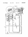
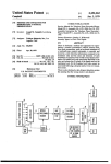
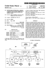
FIG. 1 is a block representation of the present wire
afterloader illustrating the placement of the remote safe
and wire driver in a treatment room separate from the
control console;
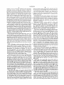
FIG. 2 is a functional block diagram of the control
console of FIG. 1;
catheter. This test is performed by extending a dummy
FIG. 3 is a left side elevational view of the remote
wire through each catheter tracing the treatment pro?le
wire driver of FIG. 1 with a portion broken away illus
intended for the active wire.
trating the placement of the active and dummy wire
The dummy wire drive apparatus is substantially
storage and guide channels and of wire drive assemblies
identical to that previously described for the active 35 and wire position detectors;
wire, although no emergency retraction system is incor
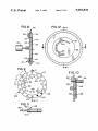
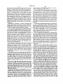
FIG. 4 is an expanded view of the wire movement
porated. Thus, undue slippage or jamming of the
apparatus of FIG. 3;
dummy wire, or a failure to retract fully, signals a fault
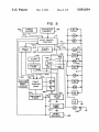
FIG. 5 is a block diagram of the wire driver control
condition which precludes active wire extension. Im
portantly, this fault condition is registered, not merely
by the computer afterloader, but in hardware interlocks
of the remote wire driver apparatus itself, whereby
circuitry;
this manner, multiple catheters may be positioned
nector;
within a patient to facilitate the more complete treat
ment of the cancerous tissue area in one radiation appli
select turret assembly showing the catheter locking
FIG. 6 is a block diagram of a sanity timer of FIG. 5;
FIG. 7 is a sectional view taken along line 7-7 of
FIG. 12 of the catheter select turret assembly;
extension of the active wire will be precluded even
FIG. 8 is a sectional view taken along line 8-8 of
though the computer may have failed to register the
FIG. 12 of the catheter select turret assembly;
FIG. 9 is a rear elevational view of the rotating turret
fault condition.
45
A similar fault detection/protection arrangement is
of the turret assembly;
provided in connection with the optional multiple cath
FIG. 10 is a sectional view taken along line 10-10 of
FIG. 9 of the rotating turret further illustrating the
eter turret. In this connection, the present invention
may advantageously incorporate a turret arrangement
placement of a catheter connector therein;
permitting connection of up to ten separate catheters. In 50 FIG. 11 is a side elevational view of a catheter con
FIG. 12 is a front elevational view of the catheter
cation session. Under afte'rloader computer control
each catheter is accessed, in turn, and the appropriate
plate;
pre-programmed treatment regime implemented. This
operation;
regime includes the above described catheter pretesting
by ?rst extending the dummy wire.
control operation; and
It is imperative that no attempt be made to extend the
dummy and active wires unless the turret is properly
indexed at a valid catheter location having a catheter
inserted therein. Consequently, detectors are ,provided
to signal both the existence of the catheter and the
proper indexing of the turret. Again, a turret or catheter
FIG. 13 is a ?owchart depicting console computer
FIGS. 14 and 15 are ?owcharts depicting wire driver
FIG. 16 is an alternative embodiment for a pinch
roller control assembly of FIG. 4.
.
DESCRIPTION OF THE PREFERRED
EMBODIMENT
The remote afterloader of the present invention, as
fault condition is registered, not merely by the com 65 shown in its most general form in FIG. 1, includes a
computerized control console 10 located in a control
puter, but by the remote wire driver apparatus thereby
assuring proper fault-induced inaction regardless of
computer operation.
room 12 and a remote safe and delivery wire driver 14
located in a treatment room 16. Federal regulations
5,092,834
7
8
require, in view of the high radiation levels associated
length of dummy guide channel 67 is selected such that
with high activity sources, that patients undergoing
the forward end of the dummy wire will be retracted to
a non-interfering position 69 when the opposed rear
ward end thereof abuts a dummy park switch 73 at
channel end 71. The channels 66 and 67 are broadly
radiused, preferably to about 80 mm, to minimize wire
friction therewith.
treatment be placed in shielded treatment rooms iso
lated from the attending physicians and other personnel.
Thus, the treatment room 16 complies with appropriate
federal regulations for shielding and, further, is pro
vided with an entrance door interlock 18 to automati
cally retract, as discussed in more detail below, the
active source upon entrance of non-patient personnel
It should be note that other channel constructions are
contemplated by the present invention. Any construc
tion providing for the low friction storage of a predeter
mined length of delivery wire, and without substantial
into the treatment room. A data and control bus 20 0
interconnects the console 10 with the remote drive 14.
openings or volumes into which the wire might buckle,
The data and control bus 20 of the present embodiment
should be satisfactory.
is an RS 422 link which connects console 10 to a micro
Referring to FIG. 3, the respective active and
processor controlled controller 13 of wire driver 14.
FIG. 2 is a block illustration of the control console 10 5 dummy wire channels merge in a “Y” or wishbone
channel connector 82, thereafter forming a single out
which includes a computer 22 of conventional availabil
put channel 83 operatively interconnected with the
ity incorporating a color monitor 24, a keyboard 26, a
printer 28 and a ?oppy disk drive 30. More speci?cally,
the computer is of the well-known 80386 processor
variety and includes an additional 40 M-byte hard drive.
An uninterruptible power supply 32 is provided to pro
tect against losses of power during on-going treatment
sequences. Uninterruptible power supply 32 also pro
vides power to the wire driver 14.
Also included with the console 10 of FIG. 2 are vari
ous annunciators and speci?c control function input
buttons. Error 34, horn 35, safe 36 treatment room door
open 38, and armed 40 annunciators, as well as stop 42,
treatment 44, and reset 122 keys and buttons are pro
vided on the control console itself. A similar panel of
annunciators and switches is provided at the treatment
room door and at the remote wire driver. The later
panels are both controlled from the wire driver control
ler 13.
‘
FIG. 3 illustrates various structural features of the
remote driver 14 used to extend treatment wires into a
catheter 55 for patient treatment. There are two deliv
ery wires, one active and one dummy. Each is of ap
turret 56. The wishbone connector 82 is milled to the
ultimate channel working dimension through which the
respective active and dummy wires pass directly.
The active wire drive and emergency retraction sys
tem 84 is shown in FIG. 3 and in enlarged form in FIG.
4. The dummy wire drive system 86 is identical, except
that the emergency retract motor 113 and its drive
assembly 108 is omitted. The uppermost capstan 94 and
pinch roller 96 de?ne the stepper motor 88 wire drive
assembly. Stepper motor 88 is beneath backing plate 76
and is shown in dotted lines Under computer stepper
control from wire driver control 13, stepper motor 88
moves the active wire 90 along the previously identi?ed
path 66 in both the extension (upward) and retraction
directions. As described in more detail below, the active
wire is extended to the maximum treatment position
then, as required by the prescribed treatment pro?le,
retracted in precisely timed intervals of predetermined
distance until the entire treatment cycle for the given
catheter has been completed.
As shown in FIG. 4, the stepper motor 88 drive as
sembly includes a rubber surfaced capstan 94 which is
proximately 0.5 millimeters in diameter. In the pre
ferred arrangement, the active delivery wire has an 40 rotated by the stepper drive motor 88. A rubber pinch
roller 96 is pivotally mounted at a pivot 98 and urges
overall length of 2.1 meters and contains a 10 millimeter
active wire 90 against the capstan 94 when pull-type
long seed of activated iridium spaced 1 millimeter from
solenoid 100 is energized. As can be seen in FIG. 4,
the forward end thereof. The dummy wire is 1.8 meters
sections of the guide channel 66 have been removed so
in length and does not contain iridium seed.
The iridium seed of the active wire is typically irradi 45 that the pinch roller 96 and capstan 94 can physically
contact the drive wire 90. The remaining sections of
ated to an activity level of 10 curies and, therefore,
channel 66 guide the wire 90 so that it remains substan
represents a potentially dangerous source of radiation
tially straight and runs parallel to the plane of capstan
that must be properly stored when not in use. A lead
safe 58 is provided for this purpose. In the preferred
94 rotation.‘
Below the drive capstan 94 is the encoder drive as
embodiment safe 58 comprises a lead sphere having a
sembly 102. It is substantially identical to the above
radius of approximately 106 mm. Referring still to FIG.
described wire drive assembly except that an encoder
3, the safe 58 is provided with a 90 degree radius cylin
238 which is connected through plate 76 to an encoder
drical channel 60 of sufficient diameter to pass the ac- .
shaft or capstan 104 is substituted for the stepper drive
tive wire source. The channel 60 defines a lower inlet 62
motor 88. When active pull-type solenoid 106 is ener
through which the active wire feeds from its guide and
gized and moves a pinch roller to engage the wire 90
storage channel 66, discussed in more detail hereinafter,
with capstan 104, movement of the wire 90 rotates cap
and an outlet 64 from which the active wire source is
stan 104. Encoder 238 responds to the rotation of cap
extended, thereafter, through a turret 56 and into the
stan 104 by sending wire movement indicating pulses to
active catheter 55.
The active and dummy wire guide channels 66 and 60 controller 13 which uses the pulses to track the position
of the active source in wire 90.
67, respectively, are made of stainless steel tubes which
The lowest capstan, used only in connection with the
are connected by connectors 80 to a backing plate 76.
active wire drive and retract system 84, de?nes the
The overall length of the active channel 66 is selected
emergency retract assembly 108. This assembly differs
such that the 10 mm active portion of the active wire 90,
i.e., the iridium seed, will be substantially centered in 65 from the stepper motor drive assembly in two important
aspects. First, the capstan 112 is driven from a conven
the safe 58 at its midpoint 68 when the opposed rear
tional, non-stepper type DC motor 113. Second, the
ward wire end abuts a park switch 72 positioned at end
pinch roller controlling solenoid 114 is of the push-type
70 of the active channel. In similar fashion, the overall
5,092,834
10
and includes a spring 116 which biases a pinch roller 118
widened diameter 158 (FIG. 10) adapted to receive a
against the capstan 112. Solenoid 114 power is required
to retract the pinch roller 118 thereby disengaging the
catheter locking ?ange 152 therein.
A circular catheter locking plate 160 is mounted adja
wire 90 from the emergency retract capstan 112. In the
event of a computer failure, power failure, or other
cent the outside of the turret 128 for limited rotation
with respect thereto. As shown in FIG. 12, the locking
plate 160 is provided with a plurality of holes 162, with
narrowed annular extensions 164, the holes having spac
ings corresponding to those of the catheter holes 156 in
the turret. Thus, the locking plate may be rotated to
system loss of control, power is dropped to emergency
retraction solenoid 114, thereby automatically engaging
the wire 90 with emergency retraction capstan 112,
while emergency battery power is simultaneously ap
plied to emergency retraction motor 113. As this is a
admit passage and positioning of one or more catheters
conventional DC motor, no special control or stepping
instructions are required. Emergency retraction may be
in the turret. Following catheter insertions, the locking
plate 160 is rotated until the narrower annular exten
sions 164 are received within catheter connector reces
effected even though other portions of the afterloader
system, including the computer 22 and controller 13 are
inoperative.
15
Alternatively, emergency retraction assembly 108
could be constructed using a pull-type solenoid 114' and
ses 154 thereby looking all catheters against inadvertent
removal.
It is essential to establish the existence of a catheter in
the active catheter position 55 as a prerequisite to wire
a jointed pinch roller control arm as shown in FIG. 16.
In FIG. 16 components performing the same function as
in FIG. 4 are given the same reference number.
extension, particularly extension of the active wire. The
active catheter position is de?ned by the uppermost
Two over-travel optical sensors provide an additional
level of protection and redundancy to the system. These
erly aligned immediately above the turret/stepper
length of the active wire, e.g., 1500 mm, thereby assur
ing that some portion of the wire will always remain
immediately above the active catheter position. Optical
adjacent the respective over-travel sensor. Therefore,
ward and an optical receiver for receiving re?ected
light from beneath the sensor. When the cylindrical tip
hole 156 of the turret 128, so long as that hole is prop
motor axis. In this position, a wire extended from the
output channel 83 (FIG. 3) directly enters the active
sensors 194 and 195 (FIG. 3) are mounted along respec
catheter 55 mounted adjacent thereto.
tive active and dummy wire channels 66, 67 immedi
FIG. 10 illustrates the orientation of a catheter 54 in
ately below the wire drive systems 84 and 86. The com 25
the active catheter position 55. An optical catheter-in
puter control system is pre-programmed to accept a
place sensor 168 is mounted to the ?xed inner race 130,
maximum treatment pro?le well below the 2lOO mm
the detection of a “no wire” condition by either over
sensor 168 includes an optical source, pointed down
travel sensor 194, 195 necessarily signi?es system mal
function terminating treatment and mandating emer
gency active wire retraction.
An additional optical sensor 190, called the home 35
member 150 of a catheter connector extends inwardly
from the turret, light from the source of optical sensor
168 will be re?ected and returned to the receiver. A
sensor, is placed in channel 83 to detect the presence
and absence of a delivery wire. The home sensor 190 is
the index point against which source positioning is mea
control 13.
signal indicating the receipt of re?ected light is sent to
,
Before the wire is extended into a catheter, it is im
sured. The home sensor is used to detect when a drive
portant to assure that the turret 128 will not rotate dur
' ing treatment. The inside face of turret 128 includes a
wire tip passes the home sensor point both on extension
plurality of cylindrical locking apertures 165 (FIG. 9),
and retraction. Sensor 190 transmits signals indicating
which are angularly spaced the same as catheter receiv
the presence or absence of a wire at the home position
to control 13.
The catheter turret 56, which is shown in FIGS. 7
ing holes 156, but rotated from the catheter holes by
approximately 90°. As shown in FIG. 7, the turret as
sembly includes a locking solenoid 351 which is struc
through 12, comprises a turret 128 (FIG. 8) retained for 45 turally connected to the turret drive assembly. Solenoid
351 has a shaft 354 which is of suitable diameter to
rotating movement between inner and outer race mem
engage the holes 165. When a catheter is placed in the
bers 130 and 132, respectively. Race members 130, 132
active position 55, solenoid 351 is energized to thrust
are rigidly affixed to the housing of the remote wire
shaft 354 into a hole 165. Advantageously, the outward
driver 14 and de?ne an annular channel 134 therebe
tween. A pair of radius grooves or races 136 and 138 are 50 end of shaft 354 may be tapered to promote engagement
with a hole 165 and to slightly correct the position of
formed in opposed channel surfaces of the race mem
the active catheter. The assembly of FIG. 7 also in
bers.
cludes an optical sensor 352 which, by means of an
An annular ?ange 140, integrally formed on the pe
aperture (not shown) in shaft 354, senses the seating of
rimeter of turret 128, is received within the channel 134.
A plurality of ball-type bearings 142 are seated within 55 shaft 354 into turret 128. A signal representing such
seating is sent from optical sensor 352 to control 13.
holes 144, which holes are evenly spaced around the
Turret 56 is rotationally positioned by the coopera
turret ?ange. Bearings 142 travel within races 136, 138
tive action of a stepper motor 146 and a rotation sensing
thereby permitting the smooth rotation of the turret 128
optical encoder 353 (FIG. 3) rotationally coupled at 355
under the computer driven control of a stepper motor
to the stepper motor. Encoder 353 transmits to .wire
146 attached thereto.
drive control 13 a series of signals indicative of its rota
Placement and locking of catheters 54 into the turret
tion and sends an index position signal once per 360'
assembly 56 is best illustrated in FIGS. 8-12. As shown
rotation. The index position signal, which is common to
in FIG. 11, the end of each catheter is provided with a
rotational encoders, is used to align the components of
connector 148 de?ned, in part, by a cylindrical exten
sion member 150, an annular locking ?ange 152 and a 65 turret 56 during assembly and to identify a “home”
catheter aperture 156 at the beginning of each treatment
recess 154. A plurality of complementary catheter re
ceptacle holes 156 are evenly spaced (FIG. 9) around a
diameter of turret 128. Each hole includes a region of
During assembly, the turret shaft is rotated until the
index signal is generated by encoder 353. The turret 128
11
5,092,834
12
control 13 also begins to transmit stepper motor control
signals over communication path 415 of bus 411 to ad
is then mounted to the shaft with a ?rst (home) catheter
hole aligned with the output of guide tube 83. Thereaf
vance the dummy wire by rotating dummy wire stepper
ter, the index signal from rotational encoder 353 is used
to identify the home turret position.
When turret 128 rotation is desired, control 13 sends
stepper pulses to stepper motor 146 until the index sig
nal is generated by encoder 353. The number of stepper
control pulses between the home catheter position and
the destination catheter position, can then be sent to
motor 230.
As the dummy wire moves, it rotates capstan 417 of
dummy wire encoder 405. The movement of capstan
417, and thus the movement of the dummy wire, is
detected by encoder 405 and reported to wire driver
control 13 over path 416 of bus 411. Wire driver control
stepper motor 146 to achieve the proper rotation to O 13 stores a wire position value and continuously updates
this value in response to the signals from encoder 405.
place the destination catheter at the active location. The
Control 13 also surveys the rate of wire movement
output signals from encoder 353 are used by control 13
signals from encoder 405 to make sure that the dummy
during such rotation to check the actual turret rotation
wire is moving at substantially the same rate that step
accuracy.
per driver 230 is being commanded to move it. Should
Treatment begins when an operator enters, at console
the wire not be moving at an appropriate rate, slippage
computer 22, a treatment plan for a particular patient
is indicated and stepper motor 230 is commanded by
and the catheters connected to that patient are attached
to the connectors 156 of turret 56. The treatment plan
wire driver control 13 to reverse and thereby retract the
speci?es which turret connectors, i.e., which catheters,
dummy wire.
Assuming that the dummy wire is advancing at an
appropriate rate, it will shortly be connected to guide
tube 83 by connector 82 (FIG. 3) and passed through
are to receive treatment, the location of treatment in
distance from the home sensor 190, and the length of
time for each treatment. After entry of the plan, console
computer 22 runs diagnostic tests, checks the treatment
plan for accuracy and safety.
After safety checks by the console computer 22, it
home sensor 190. Home sensor 190 is an optical sensing
means which detects when the tip of a wire, either the
25
transmits a message over RS422 link 20 to wire driver
control 13 of remote wire driver 14. FIG. 5 is a block
active wire or the dummy wire passes therethrough.
When the wire passes through home sensor 190, wire
driver control 13 records a count called the home count
diagram of the control circuitry included in wire driver
which represents the wire position value when the tip of
14. The message on link 20 is received by controller 13
of the remote wire driver 14 which in response, per
forms a number diagnostic and safety tests within re
the wire passed the home sensor. As the wire continues
to move into and out of the catheter, the wire position
value is incremented and decremented in response to
mote wire driver 14. A response message is then re
signals from encoder 405.
turned to computer 22, indicating the success of the
Console computer 22 speci?es treatment positions in
terms of distance from the input of the catheter (output
of the wire driver). A known guide tube distance, called
tests. Console computer 22 then responds by identifying
the ?rst turret connector (catheter) which is to receive
treatment. Wire driver 14 responds to this message by
checking to see that both the dummy and the active
wires are in their fully withdrawn positions as indicated
to control 13 by the signals from active park switch 72
and the dummy park switch 73. Wire driver control 13 40
then transmits stepper motor control signals on a multi
conductor bus 411 to stepper motor 146 to ?rst “home”
the turret then place the ?rst treatment catheter, e. g., 55
.
the offset, exists between the home sensor the wire
driver outlet. Due to the offset, a treatment distance
speci?ed in a command is reached when the wire move
ment value, minus both the home count and the offset,
equals that speci?ed treatment distance.
The dummy wire continues to advance through the
turret into the treatment catheter 55 until the maximum
treatment distance has been reached by the tip of the
dummy wire. Wire driver control 13 then reverses the
wire from wire driver 14. As stepper motor 146 rotates 45 direction of rotation of stepper motor 230 to begin with
drawing the dummy wire back into wire driver unit 14.
the turret, the turret motion is sensed by encoder 353
When the tip of the wire again passes home sensor 190
and reported via bus 411 to wire driver control 13
in the withdrawal direction, wire driver control 13 is
which tracks the rotation. When catheter 55 is in the
noti?ed. The amount stored in the wire position value
active position, wire driver control 13 transmits an
should be substantially equal to the home count which
activation signal to solenoid 351 which drives the lock
was recorded when the dummy wire interrupted sensor
ing pin 354 into place. Wire driver control 13 then
190 during the wire extension operation. If these num
checks locking pin detector 352 and catheter present
bers are within a predetermined threshold of one an
detector 168 to determine if the turret is properly
other, the process is assumed to be accurate and the
locked in place and if a catheter, e.g., 55 is in the active
55 dummy wire continues to be withdrawn until it parks
turret position.
~
against park switch 73. Wire driver control 13 is noti
In order to properly check the safety of the treat
?ed when the dummy wire changes the position of park
ment, the console computer 22 next sends a command
switch 73 and ground is removed from the solenoids 403
specifying that the non-radioactive dummy wire is to be
and 407. Also, no new control signals are transmitted to
moved to the maximum treatment distance and with
stepper motor 230. After the proper operation of the
drawn. Wire driver control 13 responds to the com
treatment apparatus is determined by the extension and
mand by grounding dummy wire drive solenoid 403 and
withdrawal of the dummy wire, wire driver control 13
dummy wire encoder solenoid 407 overconductors 410
is ready to perform the requested treatment using the
and 412, respectively, of multi-conductor bus 411. The
active source wire 90. Active wire 90 movement is
other terminals of solenoids 403 and 407 are perma
nently connected to a positive voltage supply 409 via a 65 performed substantially as described above except that
the drive apparatus 84 of the active wire is used.
conductor 413. Accordingly, both solenoids 403 and
, Due to the increased hazards involved in extending
407 are energized to engage the dummy wire between
the radioactive wire 90, an emergency shutdown and
their respective pinch rollers and capstans. Wire driver
in the active position to receive the active or dummy
5,092,834
13
wire retraction system is included in the apparatus of
FIG. 5. A safety relay 401 is the heart of the emergency
shutdown and active wire retraction system. Upon the
automatic detection of any system abnormality or dif?~
culty, or upon the manual intervention by a system
operator through the actuation of a stop button, the
relay 401 is immediately de-energized and remains de
energized until the cause of the problem has been cor»
rected and the operator resets the system. When relay
401 is de-energized power is removed from the stepper
14
mally kept idle by the low level signal at the collector of
transistor 426. When this collector goes high, as will be
the case when relay 401 is de-energized timer 440 begins
to time a 30 second interval. The return of active wire
90 into contact with park switch 72 generates a reset
signal which is connected via conductor 442 to timer
440. The reset signal on conductor 442 will clear timer
440, if it is received within the 30 second time out inter
val. If it is not received within the 30 second interval, a
signal is sent from retract timer 440 to an alarm 441
motor control portion of active drive assembly 84 and
which noti?es operating personnel by means of an audi
retraction motor 113 is energized to withdraw the ac
ble alarm signal.
Fault control logic 429 responds individually to a
tive wire 92.
-
The relay 401 is directly interconnected with both the
plurality of fault signalling conditions by removing the
emergency retraction DC motor 113 and to the emer
high level signals from the bases of transistors 426 and
gency retraction capstan solenoid 114 thereby instantly
commencing the emergency retraction cycle. Upon
427. Among the signals which result in de-energizing
relay 401 are signals from door open switch 18, a reset
switch on the control panel of wire driver 14 (not
relay 401 deactivation power is removed from the re
traction solenoid 114 and power from the emergency
shown) overrun detector 194, and signals requesting
backup battery 418 is applied to the emergency retrac
tion motor 113. The emergency retraction cycle contin
Fault control logic 429 also de-energizes relay 401 in
ues until the active wire 90 is fully retracted, as deter
mined by wire engagement with the park switch 72.
Relay 401 includes a plurality of stationary contacts
422 and 423, a pair of movable contacts 419 and 420 and
a coil 421. Coil 421 is energized for normal operation by
connection to the power supply 409 and to ground via
a fault interrupter circuit 425. Fault interrupter 425
comprises a pair of transistors with their emitter-collec
tor paths serially connected. Both transistors, in normal
operation, receive from fault control logic 429 high
level signals at their bases so that low resistance path is
presented from coil 421 to ground. When coil 421 is
energized, armatures 419 and 420 of relay 401 are pulled
down so that armature 419 connects power from power
supply 409 to stationary contact 422 which is connected
to active drive stepper motor 88, active drive enable
solenoid 100, encoder 238, encoder solenoid 106 and
emergency retract solenoid 114. While relay 401 re
retraction received from control 13 on a conductor 431.
response to signals from a pair of activity timers 124 and
126.
The ?rst of the activity timers, timer 124, monitors
the ability of wire driver control 13 to function. Control
13 transmits a periodic signal on a bus 604 approxi
mately once every 100 milliseconds, but only when the
computer hardware and software are functioning prop
erly If this signal is lost for more than about 100 milli
seconds, the timer 124 sends a fault signal to fault con
trol logic 429 which, in turn, releases the relay 401.
The activity timer 124 actually comprises a pair of
redundant 100 millisecond timers 610 and 611 (FIG. 6).
Unless reset every 100 milliseconds by signals from
control 13, each timer 610 and 611 will generate a time
out signal on a respective one of conductors 612 and
613. Such time-out signals are connected to fault con
trol logic 429 and cause de-energization of relay 401.
The reset signals from control 13 comprise 8 binary
mains energized, the active wire drive is capable of 40 digits and a strobe signal. To constitute proper reset
signals, a given reset signal must be exactly one greater
moving the active wire 90 as directed by wire driver
than the immediately preceding reset signal. The 8 bit
control 13 and retraction solenoid 114 is energized to
reset signal portion is received on path 609 of bus 604
release any engagement with active wire 90.
and stored in a buffer 601, the outputs of which are
When a fault occurs, fault control logic 429 removes
the high level signal from the bases of one or both of the 45 applied to an 8 bit comparator 603. Timer 124 also in
cludes an 8 bit counter 602 which counts modulo 256,
transistors 426 and 427, de-energizing relay 401. In the
the incoming strobe signals which are connected to
de-energized state, the armature of relay 401 moves up
counter 602 via path 605. The outputs of counter 602
and contact 420 touches contact 423 which is connected
are also applied as inputs to comparator 603 where the
to the minus or ground terminal of DC retraction motor
counter bits are compared with the contents of buffer
113. The positive terminal of retraction motor 113 is
directly connected to battery 418. Contact 420 of relay
401 is connected to ground via the normally closed
contact of active wire park switch 72. Should relay 401
be de-energized while active wire 90 is extended, power
is removed from the active wire stepper drive 84 includ
ing the retraction solenoid 114 and ground is applied to
retraction motor 113 via relay 401 and active park
switch 72. Releasing solenoid 114 engages the DC re
traction capstan 112 with active wire 90, and grounding
the motor 113 starts the retraction operation. When the
end of active wire 90 presses park switch 72, the active
wire is safely stored in the drive apparatus and the
ground connection is removed from motor 113 to stop
601. When the compared values match, which they
should during normal operation, a logic I reset signal is
transmitted by comparator 603 to a ?ip-?op 607 which
buffers the reset signal and conveys it to timers 610 and
611 before they time out Alternatively, when the values
of counter 602 and buffer 601 do not match, indicating
system error, a logic 0 signal is generated by compara
tor 603 and timers will transmit fault signals to fault
control logic 429 when they time out. The counter is
initially synchronized with the reset signals from con
trol 13 by a clear signal transmitted to counter 602 on
bus 604. The requirement that the 10 millisecond reset
signals follow a prescribed sequence provides great
assurance that control 13 is functioning properly.
The second activity timer 126 commences timing
A timer 440 is activated during each emergency re 65
whenever the active wire 90 is extended. That is, when
traction to time the retraction and cause an audible
ever the active wire is not pressing the active park
alarm when the retraction is not completed within ap
‘switch 72. A maximum time of about 20 minutes is
proximately 30 seconds. Retraction timer 440 is nor
its retraction operation.
15
5,092,834
16
A patient treatment record, including proposed treat
ment pro?le, is printed 314 prior to each treatment
allotted for active wire extension which time limit ex
ceeds the duration of the longest treatment pro?le antic
ipated. Failure of the active wire to return to the parked
session. Actual initiation of a treatment session requires
actuation of a key switch 316 by the doctor or other
position at least once every 20 minutes indicates a prob
personnel having appropriate authority.
lem necessitating emergency active wire retraction.
The computer 22 then transmits an enable treatment
command to control 13. The control 13 then performs a
number of safety tests 318 (FIG. 14) in response to the
enable command. Speci?cally, the control 13 veri?es at
For the purposes of the treatment timer 126 over
sight, the park switch 72 signals the full retraction or
parking of the active wire. In the absence of the re
quired park signal within the predetermined time limit,
the timer 126 signals fault control logic 429 which re 10 318 that the treatment room door is closed; that the
console-to remote driver communications bus 20 is
leases relay 401.
functioning;
that both active and dummy wires are
It will be appreciated that the above described run
parked;
that
the
wire position sensors are functioning;
safety relay 401 system provides a highly reliable means
and,
that
the
emergency
backup battery voltage is
for forcing the immediate retraction of the active wire
proper.
40 in the event of computer or other failure. Impor
tantly, this system is self-contained on the remote driver
After satisfactorily passing the tests of 318, wire
driver control 13 returns a command completed or OK
message to computer 22 at block 319 and awaits the next
command which will be a catheter select command,
14 chassis; and is of simple design thereby minimizing
likelihood of failure; and incorporates backup power to
further eliminate the possibility of emergency retraction
20 specifying a catheter location. Upon receipt of the cath
failure.
eter command, the turret position is set and checked at
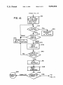
FIGS. 13 through 15 illustrate overall computer con
320 by “homing" the turret, controlling stepper motor
trolled operation of the present remote wire afterloader
146 to rotate to the speci?ed position and locking the
system. Upon system power-up 300 and initial console
turret 128 by the solenoid 351. The turret is repositioned
self-test 302, a main menu 304 permits optional courses
at 322 and rechecked at 324 if the initial position is not
correct. During steps 320 and 324 the turret is also
checked for the presence of a catheter in the selected
of action including exiting the program 306 thereby
permitting use of computer 22 for other tasks.
Patient treatment information, including the pro
posed treatment pro?le, must be entered 308. Such
position.
In step 325, another command complete message is
pro?les typically include a listing of each treatment
position, by distance measured from the catheter outlet
sent to computer 22 and wire driver control 13 awaits a
dummy position command specifying a dummy wire
position in block 325. When the dummy position com
of wire driver 14, as well as the treatment dwell time at
each such position.
mand is received, wire driver 14 tests the ?rst catheter
This information is checked 310 to verify, for exam
position by cycling the dummy wire at 326. The wire
ple, that the selected pro?le does not violate system or 35 driver control 13 selects the dummy wire by grounding
medically based operational rules. Speci?cally, in its
drive solenoid 403 and outputting a series of stepper
present and preferred arrangement, pro?le parameters
motor commands suf?cient to move the dummy wire
must not include treatment positions exceeding 1500
millimeters or position dwell times exceeding 60 sec
approximately 5 millimeters beyond the dwell location
speci?ed for the catheter under test.
More speci?cally, the driver control 13 ?rst calcu
onds. Further, the dwell positions must be arranged in
descending order and not be closer together than a
lates the number of steps required to extend the wire to
the desired maximum position (including the 5 millime
ter overextension) and the corresponding number of
pulses expected from the dummy wire encoder 405.
predetermined distance as speci?ed during system ini
tialization, i.e., at 312.
The requirement for descending order dwell posi
tions is important to proper operation of the present
afterloader particularly in view of the extremely ?ne
diameter wire for which the present system is intended
to operate. Notwithstanding the dummy wire pretesting
45 These calculations are based on a reference point de
of each catheter to verify that an ultra-thin wire can be
moved to the requisite dwell positions, there always
dummy wire position is achieved.
During dummy wire extension, the control 13 is per
remains some possibility than an ultra-thin wire will
forming cross-checks to verify that no obstructions or
?ned by the home optical sensor 190, located adjacent
the turret. Stepping of the dummy stepper 230 motor
now commences and continues until the speci?ed
become jammed precluding further inward movement.
jams have been encountered. First, wire jams are deter
mined by comparing the number of encoder 405 pulses
On the other hand, once a wire has been inserted to its
received per stepper motor step. Advantageously, this
maximum treatment position, the likelihood of jamming
upon the retraction of that wire is extremely small. 55 test may be performed only after a predetermined num
Therefore, it is preferable to commence treatment at the
ber of steps have been taken to save computer re
maximum dwell position whereby the active wire may
immediately be retracted should the computer detect
undue wire slippage at the drive capstan. This condi
tion, as noted, is sensed by comparing the rate of wire 60
sources. In the present embodiment, such a comparison
is performed after each block of 33 stepper motor steps.
If pulses stop, or fall below the expected rate, the wire
is retracted and a jam condition is annunciated.
movement detected by the encoders e.g., 238 with the
rate of wire movement requested of the stepper. motors
e.g., 88.
A maintenance capability 312 is accessible to quali
?ed personnel for the purpose of source loading, un 65
After achieving the speci?ed dummy wire position,
wire driver control 13 sends an OK signal, and awaits a
retraction signal at 327. The dummy wire is fully re
tracted in block 328 to terminate the dummy wire test
cycle. Upon retraction, the length of the dummy wire is
loading, calibration, and the setting of treatment pro?le
again checked to con?rm that the wire has not broken.
parameter limits such as maximum dwell time and mini
mum dwell step sizes.
This check is performed by comparing the stored home
count with the wire movement value which should be
5,092,834
17
18
1. Apparatus for moving a radioactive source formed
at the end of a delivery wire into and out of a guide tube
connected to a patient for the treatment of said patient,
substantially equal. The wire driver control 13 signals
the successful completion of retraction to computer 22
and awaits an active wire command in block 330.
said apparatus comprising:
The active wire command from computer 22 speci?es
a delivery wire with a source end;
the maximum treatment position for the active wire. 5
a guide tube;
The active wire is then extended to the furthest treat
a program controlled master control unit means re
ment position at 332 (FIG. 14). Extension of the active
sponsive to operator interaction for establishing a
wire is substantially identical to that of the previously
radioactive source position within said guide tube
described dummy wire. The wire is then precisely posi
for the treatment of said patient and for generating
tioned at the ?rst treatment location by, as before, ?rst
treatment command signals specifying said posi
over-extending the wire by approximately 5 millime
ters. Wire jamming and obstruction tests are performed
again, as outlined with reference to extension of the
dummy wire.
tion; and
'
During the treatment phase, the control 13 continues
to monitor system safety indices at 334, including the
long term watchdog timer 126. Since the active wire is
fully retracted and parked between each catheter treat
ment pro?le, this timer re?ects active wire extension
beyond the maximum treatment pro?le allowed by the 20
computer. In short, this timer ?ags a potentially hazard
'
a remote wire driver unit, said unit comprising:
a motor means to drive said wire;
wire moving circuitry means for moving said
source end of said wire into said guide tube in
response to wire movement control signals and
for generating source movement signals repre
senting the position of said source in said guide
tube;
program controlled wire movement control means
Upon completion of the pre-programmed dwell time
responsive to said treatment command signals
and said source movement signals for generating
for each active wire position at 338, an OK message is
sent and a new treatment position is awaited in 339. 25
Control 13 checks to see whether there are further
source end of said wire to the position speci?ed
in said treatment command signals;
ous condition necessitating emergency retraction at 336.
error detection means for sensing erroneous opera
treatment positions for that catheter at 340, if so, the
active wire is withdrawn to the speci?ed next adjacent
dwell position at 342.
Following the last treatment or dwell position for
each catheter, the active wire is fully retracted in 341,
checking the overall wire length to con?rm that the
entire wire length, including the active iridium tip por
tion, has been properly retrieved. The control 13 there
after determines by communication 342 with computer
said wire movement control signals to move said
tion in said remote wire driver unit and for gen
erating wire retraction signals in response to
such erroneous operation; and
means, independent of said wire movement control
means and said wire moving circuitry, for re
tracting said source end of said wire from said
guide tube in response to said wire retraction
35
signals.
22 whether there are additional catheter treatment pro
2. The apparatus of claim 1 wherein said error detec
?les to be run at 344. If not, a normal stop at 346 and
return to the main menu of computer 22 at 304 occur.
tion means includes either means responsive to errone
ous operation in said remote wire driver unit for re
questing retraction of said source end of said wire by
If an additional catheter treatment pro?le has been
programmed, the ?ow proceeds to block 318 (FIG. 14) 40 said wire movement circuitry; or
means responsive to a failure of said wire movement
and the turret is repositioned and checked at 320. Prior
to running each active wire treatment pro?le, the new
catheter position is checked by the dummy wire at 326
as previously described.
45
What is claimed is:
50
55
65
circuitry to remove said wire within a predeter
mined period of time for generating said wire re
traction signals.
1
t
i
it
I!
UNITED sTATEs PATENT AND TRADEMARK OFFICE
CERTIFICATE OF CORRECTION
PATENTNO-
=
5,092,834 ,
DATED
"
March 3, 1992
INVENTOMS) 1
Page 1 of 2
Anthony J. Bradshaw et al.
It is certified that error appears in the above-identified patent and that said Letters Patent is hereby
corrected as shown below:
Column 3, line 58, change "now" to -—not——.
Column 4, line 40, change "t" to --to-—.
Column 7, line 11, change "drive" to ——driver--.
Column 7,
line 27, after "36" insert —-, -—
Column 7, line
highlighted.
(comma) .
29, reference numeral "122" should
Column 7, line 44, after "contain" insert ——an-—.
Column 8, line 8, change "note" to ——noted—-.
Column 8, line 28, after "lines" insert ——.—
Column 10, line 61, change "drive" to -—driver——.
Column 10, line 66, after "treatment" insert -—.-
Column 11, line 31, after "number" insert -—of——.
Column 12, line 36, after "sensor" insert ——and--.
Column 13, line 13, change "92" to ——90——.
Column 13, line 40, change "drive" to --driver-—.
Column 14, line 3 , after "de-energized"
insert ——,-—.
Column 14, line 19, after "shown) " insert -—, --.
Column 14 , lines 28-29, after "properly"
insert
-—.——
Column 14 ,
.
line 55,
after "out" insert -—. ——
Column 15, line 15, change ‘"40" to ——90——.