1
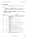
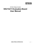
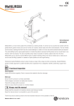
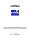
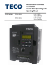
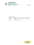
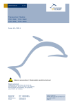
S1D13517 Display Controller
S5U13517P00C100
Evaluation Board User
Manual
SEIKO EPSON CORPORATION
Rev. 1.0
NOTICE
No part of this material may be reproduced or duplicated in any form or by any means without the written permission of Seiko
Epson. Seiko Epson reserves the right to make changes to this material without notice. Seiko Epson does not assume any liability of any kind arising out of any inaccuracies contained in this material or due to its application or use in any product or circuit and, further, there is no representation that this material is applicable to products requiring high level reliability, such as,
medical products. Moreover, no license to any intellectual property rights is granted by implication or otherwise, and there is
no representation or warranty that anything made in accordance with this material will be free from any patent or copyright
infringement of a third party. This material or portions thereof may contain technology or the subject relating to strategic
products under the control of the Foreign Exchange and Foreign Trade Law of Japan and may require an export license from
the Ministry of International Trade and Industry or other approval from another government agency.
All other product names mentioned herein are trademarks and/or registered trademarks of their respective companies.
©SEIKO EPSON CORPORATION 2009, All rights reserved.
S1D13517 Display Controller
Table of Contents
Chapter 1 Introduction . . . . . . . . . . . . . . . . . . . . . . . . . . . . . . . . . . . . 5
Chapter 2 Features . . . . . . . . . . . . . . . . . . . . . . . . . . . . . . . . . . . . . . 6
Chapter 3 Installation and Configuration . . . . . . . . . . . . . . . . . . . . . . . . . . 7
3.1 Configuration DIP Switch . . . . . . . . . . . . . . . . . . . . . . . . . . . 7
3.2 Configuration Jumpers . . . . . . . . . . . . . . . . . . . . . . . . . . . . 8
Chapter 4 Technical Description . . . . . . . . . . . . . . . . . . . . .
4.1 Power . . . . . . . . . . . . . . . . . . . . . . . . . .
4.1.1 Power Requirements . . . . . . . . . . . . . . . . . . . . . . . .
4.1.2 Voltage Regulators . . . . . . . . . . . . . . . . . . . . . . . . .
4.1.3 S1D13517 Power . . . . . . . . . . . . . . . . . . . . . . . . . .
4.2 Clocks . . . . . . . . . . . . . . . . . . . . . . . . . .
4.3 Reset . . . . . . . . . . . . . . . . . . . . . . . . . . .
4.4 Host Interface . . . . . . . . . . . . . . . . . . . . . . .
4.4.1 Direct Host Bus Interface Support . . . . . . . . . . . . . . . . .
4.4.2 Connecting to the Epson S5U13U00P00C100 USB Adapter Board
4.5 LCD Panel Interface . . . . . . . . . . . . . . . . . . . . .
4.6 GPO and PWM Connections . . . . . . . . . . . . . . . . .
.
.
.
.
.
.
.
.
.
.
.
.
. . . . . . .
. . . . . .
. . . . . . . .
. . . . . . . .
. . . . . . . .
. . . . . .
. . . . . .
. . . . . .
. . . . . . . .
. . . . . . . .
. . . . . .
. . . . . .
11
11
11
11
11
12
12
13
13
14
15
16
Chapter 5 Parts Lists . . . . . . . . . . . . . . . . . . . . . . . . . . . . . . . . . . . . 17
Chapter 6 Schematic Diagrams . . . . . . . . . . . . . . . . . . . . . . . . . . . . . . 19
Chapter 7 Board Layout . . . . . . . . . . . . . . . . . . . . . . . . . . . . . . . . . . 22
Chapter 8 References . . . . . . . . . . . . . . . . . . . . . . . . . . . . . . . . . . . 24
8.1 Documents . . . . . . . . . . . . . . . . . . . . . . . . . . . . . . . 24
8.2 Document Sources . . . . . . . . . . . . . . . . . . . . . . . . . . . . 24
S5U13517P00C100 Evaluation Board User Manual (Rev. 1.0)
EPSON
3
S1D13517 Display Controller
4
EPSON
S5U13517P00C100 Evaluation Board User Manual (Rev. 1.0)
S1D13517 Display Controller
Chapter 1 Introduction
This manual describes the setup and operation of the S5U13517P00C100 Evaluation Board. The evaluation board
is designed as an evaluation platform for the S1D13517
Display Controller.
The S5U13517P00C100 evaluation board can be used with many native platforms via the host connector which
provides the appropriate signals to support a variety of CPUs. The S5U13517P00C100 evaluation board can also
connect to the S5U13U00P00C100 USB Adapter board so that it can be used with a laptop or desktop computer, via
USB 2.0.
This user manual is updated as appropriate. Please check the Epson Research and Development Website at
www.erd.epson.com for the latest revision of this document before beginning any development.
We appreciate your comments on our documentation. Please contact us via email at [email protected].
S5U13517P00C100 Evaluation Board User Manual (Rev. 1.0)
EPSON
5
S1D13517 Display Controller
Chapter 2 Features
The S5U13517P00C100 Evaluation Board includes the following features:
• S1D13517 Display Controller (128-pin QFP)
• Integrated Silicon Solution, Inc. IS42S16800E-7TLI 128M-bit SDRAM (54-pin TSOP)
• Header with all S1D13517 Host Bus Interface signals
• Headers for connection to the S5U13U00P00C100 USB Adapter board
• Headers for connecting to LCD panels
• Header for S1D13517 GPO pins and PWM pin
• On-board 24MHz oscillator
• 14-pin DIP socket (if a clock other than 24MHz must be used)
• 3.3V input power
• On-board voltage regulator with 2.5V output
• On-board voltage regulator with adjustable 6~24V output, 40mA max., to provide power for LED backlight of
LCD panels.
6
EPSON
S5U13517P00C100 Evaluation Board User Manual (Rev. 1.0)
S1D13517 Display Controller
Chapter 3 Installation and Configuration
The S5U13517P00C100 evaluation board incorporates a DIP switch, jumpers, and 0 ohm resistors which allow it to
be used with a variety of different configurations.
3.1 Configuration DIP Switch
The S1D13517 has 2 configuration inputs (CNF[1:0]). A DIP switch (SW1) is used to configure CNF[1:0] as
described below.
Table 3-1: Summary of Power-On/Reset Options
Power-On/Reset State
SDU13517P00C100
SW1-[2:1] Config
S1D13517
CNF[1:0] Config
1 (ON)
0 (OFF)
SW1-[1]
CNF0
Host data bus is 8-bit
Host data bus is 16-bit
SW1-[2]
CNF1
Host interface is ALE bus
Host interface is i80 bus
= Required settings when using S5U13U00P00C100 USB Adapter board
The following figure shows the location of DIP switch SW1 on the S5U13517P00C100 board.
DIP Switch
SW1
Figure 3-1: Configuration DIP Switch (SW1) Location
S5U13517P00C100 Evaluation Board User Manual (Rev. 1.0)
EPSON
7
S1D13517 Display Controller
3.2 Configuration Jumpers
The S5U13517P00C100 has 6 jumpers which configure various board settings. The jumper positions for each
function are shown below.
Jumper
Function
Position 1-2
Position 2-3
J1
COREVDD
Normal
—
J2
IOVDD
Normal
—
J3
PLLVDD
Normal
—
J4
J5
IOVDD source
24MHz control
3.3V
24MHz stop
CN1 connector, pin 32
—
No Jumper
COREVDD current
measurement
IOVDD current
measurement
PLLVDD current
measurement
—
Normal
= Required settings when using S5U13U00P00C100 USB Adapter board
Jumper
Function
Position 1-2
Position 3-4
Position 5-6
J6
Clock source
On board 24MHz
Second oscillator
CLKI pin to GND
J1, J2, J3 - Power Supplies for the S1D13517
J1, J2, J3 can be used to measure the current consumption of each S1D13517 power supply.
When the jumper is at position 1-2, normal operation is selected.
When no jumper is installed, the current consumption for each power supply can be measured by connecting an
ammeter between pins 1 and 2 of the jumper.
The jumper associated with each power supply is as follows:
J1 for COREVDD
J2 for IOVDD
J3 for PLLVDD
J2, J1
J3
Figure 3-2: Configuration Jumper Locations (J1, J2, J3)
8
EPSON
S5U13517P00C100 Evaluation Board User Manual (Rev. 1.0)
S1D13517 Display Controller
J4 - IOVDD Source
J4 is used to select the source for the IOVDD supply voltage.
When the jumper is at position 1-2, the IOVDD voltage is provided by the 3.3V power supply of the board.
When the jumper is at position 2-3, the IOVDD voltage must be provided to the CN1 connector, pin 32.
J5 - 24MHz Control
J5 is used to control the 24MHz oscillator.
When no jumper is installed, the 24MHz oscillator is running.
When the jumper is at position 1-2, the 24MHz oscillator is stopped.
J6 - Clock Source
J6 is used to select the source for the clock input.
When the jumper is at position 1-2, the on board 24MHz oscillator is selected.
When the jumper is at position 3-4, the second oscillator is selected.
When the jumper is at position 5-6, the CLKI pin is forced to GND.
J5
J4
J6
Figure 3-3: Configuration Jumper Location (J4, J5, J6)
S5U13517P00C100 Evaluation Board User Manual (Rev. 1.0)
EPSON
9
S1D13517 Display Controller
Chapter 4 Technical Description
4.1 Power
4.1.1 Power Requirements
The S5U13517P00C100 evaluation board requires an external regulated power supply (3.3V / 0.5A). The power is
supplied to the evaluation board through pin 34 of the CN1 header, or pin 5 of the P2 header.
The green LED ‘3.3V Power’ is turned on when 3.3V power is applied to the board.
4.1.2 Voltage Regulators
The S5U13517P00C100 evaluation board has an on-board linear regulator to provide the 2.5V power required by
the S1D13517 Display Controller. It also has a step-up switching voltage regulator to generate adjustable 6~24V,
which can be used to power the LED backlight on some LCD panels.
4.1.3 S1D13517 Power
The S1D13517 Display Controller requires 2.5V and 3.0~3.6V power supplies.
2.5V power for COREVDD and PLLVDD is provided by an on-board linear voltage regulator.
IOVDD can be in the range of 3.0~3.6V. When J4 is set to the 1-2 position, IOVDD is connected to 3.3V. If a
different voltage is required for IOVDD, set JP4 to the 2-3 position and connect the external power supply to pin 32
of connector CN1.
10
EPSON
S5U13517P00C100 Evaluation Board User Manual (Rev. 1.0)
S1D13517 Display Controller
4.2 Clocks
The clock for the S1D13517 Display Controller is provided by a 24MHz oscillator.
The S5U13517P00C100 evaluation board has a DIP14 footprint for an optional second oscillator, Y2. This is
provided for cases requiring a different clock frequency for the S1D13517 Display Controller. To use Y2, an oscillator must be populated in the Y2 footprint and the J6 jumper placed at position 3-4.
4.3 Reset
The S1D13517 Display Controller on the S5U13517P00C100 evaluation board can be reset using a push-button
(SW2), or via an active low reset signal from the host development platform (pin 33 on the CN1 connector).
SW2
Y2
Figure 4-1: Second oscillator and Reset switch Location (Y2, SW2)
S5U13517P00C100 Evaluation Board User Manual (Rev. 1.0)
EPSON
11
S1D13517 Display Controller
4.4 Host Interface
4.4.1 Direct Host Bus Interface Support
All S1D13517 host interface pins are available on connector CN1 which allows the S5U13517P00C100 evaluation
board to be connected to a variety of development platforms.
The following figure shows the location of host bus connector CN1. CN1 is a 0.1x0.1 inch 34-pin header (17x2).
CN1
Figure 4-2: Host Bus Connector Location (CN1)
For the pinout of connector CN1, see Chapter 6, “Schematic Diagrams” on page 18.
12
EPSON
S5U13517P00C100 Evaluation Board User Manual (Rev. 1.0)
S1D13517 Display Controller
4.4.2 Connecting to the Epson S5U13U00P00C100 USB Adapter Board
The S5U13517P00C100 evaluation board is designed to connect to a S5U13U00P00C100 USB Adapter Board. The
USB adapter board provides a simple connection to any computer via a USB 2.0 connection. The
S5U13517P00C100 directly connects to the USB adapter board through connectors P1 and P2.
The USB adapter board also supplies the 3.3V power required by the S5U13517P00C100. IOVDD should be
selected for 3.3V and J4 should be set to the 1-2 position.
When the S5U13517P00C100 is connected to the S5U13U00P00C100 USB Adapter board, there are 2 LEDs on
S5U13517P00C100 which provide a quick visual status of the USB adapter. LED1 blinks to indicate that the USB
adapter board is active. LED2 turns on to indicate that the USB has been enumerated by the PC.
The following diagram shows the location of connectors P1 and P2. P1 and P2 are 40-pin headers (20x2).
P1
P2
Figure 4-3: USB Adapter Connector Locations (P1 and P2)
For the pinout of connectors P1 and P2, see Chapter 6, “Schematic Diagrams” on page 18.
Note
A windows driver must be installed on the PC when the S5U13517P00C100 is used with the S5U13U00P00C100
USB Adapter Board. The S1D13xxxUSB driver is available at www.erd.epson.com.
S5U13517P00C100 Evaluation Board User Manual (Rev. 1.0)
EPSON
13
S1D13517 Display Controller
4.5 LCD Panel Interface
The LCD interface signals are available on connectors CN3 and CN5.
Connector CN3 is 0.1x0.1 inch 40-pin header (20x2) and connector CN5 is 0.1x0.1 inch 10-pin header (5x2). For
the pinout of connectors CN3 and CN5, see Chapter 6, “Schematic Diagrams” on page 18.
On the evaluation board there is an adjustable 6~24V, 40mA max. power supply. This voltage is provided only on
connector CN3 (it is not used elsewhere on the board). It is intended for use to power the LED backlight on some
LCD panels. The voltage is adjusted by the VR1 pot.
Note
For LCD panels that use a CCFL backlight, an external power supply must be used to provide power to the inverter
for the CCFL backlight. Usually, the inverter current consumption is higher than the maximum 40mA current
available from the on-board voltage regulator.
The following diagram shows the location of the LCD panel connectors CN3 and CN5.
CN5
CN3
Figure 4-4: LCD Panel Connectors Location (CN3, CN5)
14
EPSON
S5U13517P00C100 Evaluation Board User Manual (Rev. 1.0)
S1D13517 Display Controller
4.6 GPO and PWM Connections
The S1D13517 Display Controller has 4 GPO pins and PWM pin. All the GPO pins and PWM pin are routed to the
CN4 connector. Connector CN4 is 0.1x0.1 inch 10-pin header (5x2).
The following figure shows the location of the GPO and PWM connector, CN4.
CN4
Figure 4-5: GPIO and PWM Connector Location (CN4)
For the pinout of connector CN4, see Chapter 6, “Schematic Diagrams” on page 18.
S5U13517P00C100 Evaluation Board User Manual (Rev. 1.0)
EPSON
15
S1D13517 Display Controller
Chapter 5 Parts Lists
Table 5-1: Parts List
Item
Quantity
Reference
1
1
CN1
A1-34PA-2.54DSA(71)
2
1
CN3
HIF3FC-40PA-2.54DSA
3
2
CN4,CN5
A1-10PA-2.54DSA(71)
27
C1,C3,C5,C7,C9,C11,
C13,C15,C17,C19,C21,
C23,C25,C27,C28,C31,
C32,C34,C35,C37,C43,
C45,C47,C49,C51,C53,
C55
0.1u
5
23
C2,C4,C6,C8,C10,C12,
C14,C16,C18,C20,C22,
C24,C26,C29,C33,C38,
C44,C46,C48,C50,C52,
C54,C56
0.01u
6
1
C30
2000p
7
1
C36
100u
8
1
C40
47u 10v
9
1
C41
10p
10
1
C42
1u 50V
11
1
D1
SML-310VT
12
1
D2
SML-310DT
13
1
D3
SML-310PT
14
1
D4
MBR0530
15
2
F1,F2
16
4
J1,J2,J3,J5
WL-1-2P
17
1
J4
WL-1-3P
18
1
J6
WLW-3
19
2
L1,L2
BLM21P
20
1
L3
21
3
PAD1,PAD2,PAD3
22
2
P1,P2
23
1
R1
24
3
R2,R3,R4
4
16
Part
ACF451832-222
LQH32CN100K23L
2mm diameter
PRPN202PAEN-RC
3k 1%
EPSON
10k
S5U13517P00C100 Evaluation Board User Manual (Rev. 1.0)
S1D13517 Display Controller
Table 5-1: Parts List
Item
Quantity
Reference
Part
25
49
R5,R6,R7,R8,R10,R11,
R12,R14,R15,R21,R22,
R23,R24,R25,R26,R27,
R28,R29,R30,R31,R32,
R33,R34,R35,R36,R37,
R38,R39,R40,R41,R42,
R43,R44,R45,R46,R47,
R48,R49,R50,R51,R52,
R53,R54,R55,R56,R57,
R58,R59,R60
26
1
R9
27
2
R13,R17
28
1
R16
NM
29
3
R18,R19,R20
270
30
1
R61
887k
31
1
R62
22k
32
1
R63
47k
33
6
34
1
SW1
CFS-0400MB
35
1
SW2
SKRKAEE010
36
10
37
1
U1
S1D13517
38
1
U2
TPS76915DBVT
39
1
U3
IS42S16800E (128Mbit SDRAM)
40
1
U4
TPS61040
41
1
VR1
42
1
Y1
SG-210 24MHz
43
1
Y2
XR2A-1405
0
150k
33 1%
SH1,SH2,SH3,SH4,SH5,
.100 in. Jumper Shunt
SH6
TP1,TP2,TP3,TP4,TP5,
HK-2-S
TP6,TP7,TP8,TP9,TP10
S5U13517P00C100 Evaluation Board User Manual (Rev. 1.0)
200k
EPSON
17
A
B
C
HD[15:0]
HWE#
HCS#
HRE#
PWM
TE
HD/C#
GPO[3:0]
PCLK
HD0
HD1
HD2
HALE
GPO2
GPO1
GPO0
GPO3
5
PDG4
PDG5
PDG6
PDG7
PDB0
PDB1
PDB2
PDB3
PDB4
PDB5
PDB6
PDB7
HD[15:0]
VSS
PDG3
PDG2
PDG1
PDG0
PDR7
PDR6
PDR5
PDR4
PDR3
PDR2
PDR1
PDR0
PCLK
GPO3
COREVDD
IOVDD
VSS
GPO2
GPO1
GPO0
PWM
TE
HD/C#
HALE
HWE#
HCS#
HRE#
HD0
HD1
HD2
IOVDD
U1
S1D13517
HD3
HD4
HD5
HD6
HD7
HD8
HD9
HD10
HD11
HD12
HD13
HD14
HD15
PDR[7:0]
97
98
99
100
101
102
103
104
105
106
107
108
109
110
111
112
113
114
115
116
117
118
119
120
121
122
123
124
125
126
127
128
4
CLKI
PDG3
PDG2
PDG1
PDG0
PDR7
PDR6
PDR5
PDR4
PDR3
PDR2
PDR1
PDR0
TEST0
TEST1
CNF2
CNF1
CNF0
PDG[7:0]
PLLCHGO
EPSON
RESET#
PDB[7:0]
PDG[7:0]
PHS
PVS
PDE
4
MD15
MD0
MD14
MD1
MD13
MD2
MD12
MD3
MD11
MD4
MD10
MD5
96
95
94
93
92
91
90
89
88
87
86
85
84
83
82
81
80
79
78
77
76
75
74
73
72
71
70
69
68
67
66
65
PLL
64
63
62
61
60
59
58
57
56
55
54
53
52
51
50
49
48
47
46
45
44
43
42
41
40
39
38
37
36
35
34
33
3
CORE
3
MD[15:0]
IOVDD
MD9
MD6
MD8
MD7
MDQM0
MWE#
MDQM1
MCAS#
MCLKO
VSS
MCLKI
COREVDD
MRAS#
MCKE
MCS#
VSS
IOVDD
MA11
MBA0
MA9
MBA1
MA8
MA10
MA7
MA0
MA6
MA1
MA5
MA2
MA4
MA3
IOVDD
PDG4
PDG5
PDG6
PDG7
PDB0
PDB1
PDB2
PDB3
PDB4
PDB5
PDB6
PDB7
PHS
PVS
PDE
VSS
IOVDD
COREVDD
MD15
MD0
MD14
MD1
MD13
MD2
MD12
MD3
MD11
MD4
MD10
MD5
VSS
VSS
HD3
HD4
HD5
HD6
HD7
HD8
HD9
HD10
HD11
HD12
HD13
HD14
HD15
COREVDD
IOVDD
VSS
CLKI
TEST0
TEST1
CNF2
CNF1
CNF0
VSS
COREVDD
PLLCHGO
PLLVDD
PLLVSS
RESET#
SCANEN
IOVDD
VSS
18
SCANEN
IO
MBA1
MBA0
MRAS#
MCKE
MCS#
MDQM0
MWE#
MDQM1
MCAS#
MCLKO
MA[11:0]
MCLKI R5
0
HALE R6
0
MCLKO
PAD3 2mm dia
TEST0
CNF2 R4
10k
PAD1 2mm dia
PAD2 2mm dia
C30
2000p
TEST1
R1
3k 1%
IO
SCANEN
PLLCHGO
1
2
TEST0
TEST1
2
Date:
Size
A4
Title
1
2
2.5VDD
SH3
0.01u
S1D13517
PLL
0.1u
C23
0.01u
Sheet
R3
10k
L2
0.1u
C27
L1
1
0.1u
C25
1
1
0.1u
C17
0.1u
C28
of
CNF[2:0]
ON High
OFF Low
0.01u
C18
3
IOVDD
Rev
1.2
0.01u
C29
TP3
HK-2-S
0.01u
C26
0.01u
TP2
HK-2-S
0.01u
CFS-0400MB
SW1
BLM21P
0.1u
C6
TP1
HK-2-S
C5
C10
PLL
0.01u
C16
0.1u
C9
0.01u
C4
BLM21P
0.01u
C24
0.1u
C15
0.01u
C14
C8
0.1u
0.1u
C3
C7
0.01u
C2
2.5VDD
R2
10k
WL-1-2P
1
2
0.01u
C22
0.1u
C13
0.1u
C1
CORE
Wednesday, April 22, 2009
Document Number
<Doc>
CNF0
CNF1
0.1u
J3
0.01u
0.1u
C21
C12
C11
C20
IO
CORE
WL-1-2P
J1
.100 in. Jumper Shunt
0.1u
C19
IOVDD
SCANEN
WL-1-2P
.100 in. Jumper Shunt
J2
Wire shortest.
MA8
MA10
MA7
MA0
MA6
MA1
MA5
MA2
MA4
MA3
MA9
MA11
MCLKI
MCLKO
MD9
MD6
MD8
MD7
MD[15:0]
SH2
.100 in. Jumper Shunt
SH1
2
A
B
C
D
Chapter 6 Schematic Diagrams
1
2
3
4
5
6
7
8
9
10
11
12
13
14
15
16
17
18
19
20
21
22
23
24
25
26
27
28
29
30
31
32
D
5
S1D13517 Display Controller
Figure 6-1: S5U13517P00C100 Schematic Diagram (1 of 3)
S5U13517P00C100 Evaluation Board User Manual (Rev. 1.0)
S5U13517P00C100 Evaluation Board User Manual (Rev. 1.0)
EPSON
A
B
C
D
3.3V
HK-2-S
TP5
R7
HD6
HD4
HD2
HD0
HD15
HD13
HD11
HD9
HRD#
INT
0
0
0
2
4
6
8
10
12
14
16
18
20
22
24
26
28
30
32
34
36
38
40
P2
2
4
6
8
10
12
14
16
18
20
22
24
26
28
30
32
34
36
38
40
R18
270
R20
270
Red
SML-310DT
Green
D3
SML-310PT
HD14
HD12
HD10
HD8
HD7
HD5
HD3
HD1
HWE#
4
4
POWER
ENUM
HB
ENUMARETED
SML-310VT
Orange
D2
D1
PRPN202PAEN-RC
1
3
5
7
9
11
13
15
17
19
21
23
25
27
29
31
33
35
37
39
PRPN202PAEN-RC
1
3
5
7
9
11
13
15
17
19
21
23
25
27
29
31
33
35
37
39
ENUMARETED R19
270
3.3VDD
HEARTBEAT
5
HD/C#
R15 0
HEARTBEAT
HCS# R10
R11
3.3VDD
TE R8
0
IOVDD
P1
HD[15:0]
TP6
HK-2-S
C34
0.1u
3.3VDD
R14
0
TP7
HK-2-S
TE
RESET#
HCS#
HWE#
HRE#
HD/C#
HOST I/F
2.54mm
Pin Header
3
2
1
CN1
VOUT
NC/FB
TP8
HK-2-S
2
4
6
8
10
12
14
16
18
20
22
24
26
28
30
32
34
3
TP9
HK-2-S
4
0.01u
2
Date:
Size
A4
Title
C38
0.01u
C33
0.1u
R16
NM
1
2
3
1
2
3
4
5
6
7
OUT
OE
XR2A-1405
14
13
12
11
10
9
8
SG-210 24MHz
GND
VDD
Y1
Y2
2
4
.100 in. Jumper Shunt
SH5
3
1
J5
WL-1-2P
R17
R13
33 1%
33 1%
SW2
SKRKAEE010
Y1 Ctrl
Short Disable
3.3VDD
IOVDD
IOVDD_IN
RESET
Wednesday, April 22, 2009
Document Number
<Doc>
HOST, CLK
.100 in. Jumper Shunt
SH4
0.1u
C31
SH6
Sheet
2
1
of
CLKI
3
Rev
1.2
CLKI sel
1-2 OnBoard
3-4 Socket
5-6 GND
J6
WLW-3
TP4
HK-2-S
RESET#
R9
150k
IOVDD
1
.100 in. Jumper Shunt
Installs in position 1-2 of JP4, 6.
WL-1-3P
J4
IOVDD Sel
1-2 3.3V
2-3 IOVDD_IN
2
C37
IOVDD
0.1u
C32
R12
0
3.3VDD
3.3VDD
IOVDD_IN
HD9
HD11
HD13
HD15
HD1
HD3
HD5
HD7
2.5VDD
C36
100u
GND
C35
0.1u
5
A1-34PA-2.54DSA(71)
1
3
5
7
9
11
13
15
17
19
21
23
25
27
29
31
33
TPS76915DBVT
EN#
GND
IN
U2
HCS#
HWE#
HRD#
HD/C#
INT
TE
RESET#
HD8
HD10
HD12
HD14
HD0
HD2
HD4
HD6
3
2
1
5
2
4
6
1
3
5
2mm
Pin Header
A
B
C
D
S1D13517 Display Controller
Figure 6-2: S5U13517P00C100 Schematic Diagram (2 of 3)
19
A
B
C
R59
0
3.3VDD
PCLK
PDE
PHS
PVS
GPO[3:0]
1
PDR7
PDR6
PDR5
PDG7
PDG6
PDG5
PDB7
PDB6
PDB5
PDR4
PDR3
PDR2
PDG4
PDG3
PDG2
PDB4
PCLK
PDE
PHS
PVS
CN3
PDG[7:0]
2
4
6
8
10
12
14
16
18
20
22
24
26
28
30
32
34
36
38
40
5
C40
47u 10v
2
F1
ACF451832-222
R60
0
HIF3FC-40PA-2.54DSA
1
3
5
7
9
11
13
15
17
19
21
23
25
27
29
31
33
35
37
39
GPO3
GPO2
GPO1
GPO0
3
D
PDR7
PDR6
PDR5
PDR4
PDR3
PDR2
PDR1
PDR0
5
4
5
FB
GND
SW
TPS61040
EN
VIN
U4
3
2
1
1
3
5
7
9
VR1
200k
R63
47k
R61
887k
D4
MBR0530
12VDD Ctrl
4
CN4
2
4
6
8
10
CN5
2
4
6
8
10
2
C41
10p
A1-10PA-2.54DSA(71)
3.3VDD
PDR0
PDG0
PDB0
PWM
1
3
5
7
9
A1-10PA-2.54DSA(71)
3.3VDD
PDB7
PDB6
PDB5
PDB4
PDB3
PDB2
PDB1
PDB0
4
GPO0
GPO2
L3
LQH32CN100K23L
IOVDD
12VDD
LCD
PDB3
PDB2
PDG7
PDG6
PDG5
PDG4
PDG3
PDG2
PDG1
PDG0
PDB[7:0]
1
EPSON
3
20
C42
1u 50V
1
2
F2
ACF451832-222
Ext LCD
GPO
PDR1
PDG1
PDB1
IOVDD
GPO1
GPO3
IOVDD
3
PDR[7:0]
3
12VDD
3
R62
22k
12VDD
TP10
HK-2-S
MA[11:0]
MDQM0
MWE#
MCAS#
MRAS#
MCS#
MBA0
MBA1
MD[15:0]
2
Date:
Size
A4
VDD
DQ0
VDDQ
DQ1
DQ2
VSSQ
DQ3
DQ4
VDDQ
DQ5
DQ6
VSSQ
DQ7
VDD
DQML
WE#
CAS#
RAS#
CS#
BA0
BA1
A10
A0
A1
A2
A3
VDD
VSS
DQ15
VSSQ
DQ14
DQ13
VDDQ
DQ12
DQ11
VSSQ
DQ10
DQ9
VDDQ
DQ8
VSS
NC
DQMH
CLK
CKE
NC
A11
A9
A8
A7
A6
A5
A4
VSS
54
53 R22
52
51 R24
50 R26
49
48 R28
47 R30
46
45 R32
44 R34
43
42 R36
41
40
39 R39
38 R41
37 R43
36
35 R46
34 R48
33 R50
32 R52
31 R54
30 R56
29 R58
28
0.01u
0.1u
C53
0.1u
C55
0.01u
C46
0.01u
C54
0.1u
C45
Wednesday, April 22, 2009
Document Number
<Doc>
LCD, DRAM
C52
0.01u
0.1u
C44
0.1u
Sheet
0
0
0
0
0
0
0
0
0
0
0
0
0
0
0
0
0
0
1
3
1
0.01u
C48
0.01u
C56
0.1u
C47
IS42S16800E(128Mbit SDRAM)
1
2
3
4
5
6
7
8
9
10
11
12
13
14
15
16
17
18
19
20
21
22
23
24
25
26
27
U3
C43
0
0
0
0
0
0
0
0
0
0
0
0
C51
3.3VDD
Title
MA10
MA0
MA1
MA2
MA3
R37
R38
R40
R42
R44
R45
R47
R49
R51
R53
R55
R57
0
0
0
R31
R33
MD5
MD6
R35
0
0
R27
R29
MD3
MD4
MD7
0
0
0
R23
R25
R21
MD1
MD2
MD0
3.3VDD
2
0.1u
C49
of
3
0.01u
C50
MA11
MA9
MA8
MA7
MA6
MA5
MA4
MDQM1
MCLKO
MCKE
MD8
MD10
MD9
MD12
MD11
MD14
MD13
MD15
3.3VDD
Rev
1.2
A
B
C
D
S1D13517 Display Controller
Figure 6-3: S5U13517P00C100 Schematic Diagram (3 of 3)
S5U13517P00C100 Evaluation Board User Manual (Rev. 1.0)
S1D13517 Display Controller
Chapter 7 References
7.1 Documents
• Epson Research and Development, Inc., S1D13517 Hardware Functional Specification, document number
X92A-A-001-xx
• Epson Research and Development, Inc., S5U13U00P00C100 USB Adapter Board User Manual, document
number I00Z-G-018-xx
7.2 Document Sources
• Epson Research and Development Website: http://www.erd.epson.com
S5U13517P00C100 Evaluation Board User Manual (Rev. 1.0)
EPSON
21
S1D13517 Display Controller
Change Record
X92A-G-001-01 Revision 1.0 - Issued: May 8, 2009
• initial release
22
EPSON
S5U13517P00C100 Evaluation Board User Manual (Rev. 1.0)
International Sales Operations
AMERICA
ASIA
EPSON ELECTRONICS AMERICA, INC.
EPSON (CHINA) CO., LTD.
2580 Orchard Parkway
San Jose, CA 95131,USA
Phone: +1-800-228-3964
7F, Jinbao Bldg., No.89 Jinbao St.,
Dongcheng District,
Beijing 100005, CHINA
Phone: +86-10-6410-6655 FAX: +86-10-6410-7320
FAX: +1-408-922-0238
SHANGHAI BRANCH
EUROPE
EPSON EUROPE ELECTRONICS GmbH
Riesstrasse 15, 80992 Munich,
GERMANY
Phone: +49-89-14005-0
FAX: +49-89-14005-110
7F, Block B, High-Tech Bldg., 900, Yishan Road,
Shanghai 200233, CHINA
Phone: +86-21-5423-5522 FAX: +86-21-5423-5512
SHENZHEN BRANCH
12F, Dawning Mansion, Keji South 12th Road,
Hi-Tech Park, Shenzhen 518057, CHINA
Phone: +86-755-2699-3828 FAX: +86-755-2699-3838
EPSON HONG KONG LTD.
20/F, Harbour Centre, 25 Harbour Road
Wanchai, Hong Kong
Phone: +852-2585-4600
FAX: +852-2827-4346
Telex: 65542 EPSCO HX
EPSON TAIWAN TECHNOLOGY & TRADING LTD.
14F, No. 7, Song Ren Road,
Taipei 110, TAIWAN
Phone: +886-2-8786-6688 FAX: +886-2-8786-6660
EPSON SINGAPORE PTE., LTD.
1 HarbourFront Place,
#03-02 HarbourFront Tower One, Singapore 098633
Phone: +65-6586-5500
FAX: +65-6271-3182
SEIKO EPSON CORP.
KOREA OFFICE
50F, KLI 63 Bldg., 60 Yoido-dong
Youngdeungpo-Ku, Seoul, 150-763, KOREA
Phone: +82-2-784-6027
FAX: +82-2-767-3677
SEIKO EPSON CORP.
SEMICONDUCTOR OPERATIONS DIVISION
IC Sales Dept.
IC International Sales Group
421-8, Hino, Hino-shi, Tokyo 191-8501, JAPAN
Phone: +81-42-587-5814
FAX: +81-42-587-5117
Document Code: X92A-G-001-01
Issued 2009/04/28
Mouser Electronics
Authorized Distributor
Click to View Pricing, Inventory, Delivery & Lifecycle Information:
Epson:
S5U13517P00C100