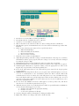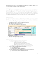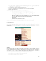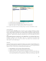
1
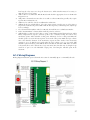
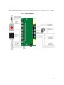
3.
4.
5.
6.
7.
8.
9.
how long the relay stays on to keep the button active. Click Switch Contacts if necessary, to
make the relays reverse acting.
Add a reader for each Elevator. Edit the Reader and check the appropriate boxes on the Reader
Program screen.
Add points to the Reader. Because there is no strike etc, Elevator Readers generally only require
2 points: Door and Last Access.
Add Areas for each floor, but do not add Readers at this time.
Add Interlocks for each Elev/Floor. Select the output points created in step 2. Select Start or
Stop based on whether the point is NO or NC. If other logic may command a point, adjust logic
level accordingly.
Go to the Reader/Area Editor and select a Reader, then add Areas to each Elevator Reader.
In the “Command List” column, add an interlock point for each area.
Add Schedules so that users don’t have to swipe a Card during normal business hours. Add a
Binary Output Event Sequence Software point to the controller hosting the button relay
momentary points. Add a Schedule to that point. Add Logic level 2 to that point: When the
schedule point is on, start the button points, else Auto the same points. Make the logic evaluate
more often than the duration of the momentary outputs. In other words: if the momentary
outputs are set to be ON for 10 seconds, make the logic evaluate every 5 to 8 seconds. This
should keep the momentary points ON the whole time that the Schedule is ON. There are limits
to how many lines can be written into a logic statement (125). Another way of doing the logic
would be to put it on each individual output point, referencing the Schedule point in the
statement.
AC-3 Wiring Diagrams
Wiring diagram with strike powered from the AC-3. Can be “Normally Open” or “Normally Closed.”
27